Transcription
BUILD YOUR OWN RC TURBINE ENGINEBy Bob EnglarThis Turbine engine is “state of the art” as it currently applies and is designed to deliver high power withreliability. While using the same compressor and turbine wheels as in the KJ66 design, it is simpler tomake and cheaper to maintain in the longer term. The KJ66 provided a quantum leap in the design of
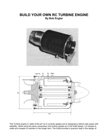
The Following parts are availablPage 3 of 16miniature gas turbines and we should all be grateful to the design team for placing it in the publicdomain. Starting at the front of the Engine, the compressor wheel shroud is machined aluminum. Thediffuser requires a simple turning and milling operation as the 6 deg slope is on the front of the wedgeswith a mating slope on the diffuser cover. Therefore the diffuser can be milled while held flat on thetable. Also the front bearing can be replaced by simply removing the compressor shroud and shaft. Thediffuser cover is slotted for an “O” ring to provide a case seal and the assembly is held in place in thecase by a ring of 12 machine screws. The front end is extremely rugged and should survive even themost severe crash. The shaft is made from 4140 (60 ton, 90 ton after heat treatment) steel and runs inceramic ball races with front preload provided by a wave washer bearing on the front ball race outerring. The bearings also ride in ‘O’ rings. This keeps them centralized when the shaft tunnel expandswith temperature and also results in quieter running. Lubrication is provided by mixing 5% Jet oil withthe kerosene and a “Tee” in the external fuel line delivers this to the front bearing. Air under casepressure is fed to the front bearing via slots in the rear of the diffuser and this carries the lubricationdown the shaft tunnel through the rear bearing to provide it’s lubrication, then to atmosphere via theturbine exhaust. This system has several advantages: As soon as the engine gets fuel, it getslubrication. The kero/oil mix with air provides good cooling as well as lubrication for bearings. Aseparate oil tank is not required so its one less thing to have to worry about. The downside is a slightincrease in fuel consumption. The combustion chamber incorporates radial air jets at the front and thesecan be easily adjusted to optimize the combustion burn pattern. The rear lip of the chamber slots intothe inside of the NGV outer ring and this provides an extremely smooth transition for the high velocitygas. The rear of the inner sleeve slides over a matching rebate on the inner NGV ring and this alsoprovides a step free gas path. The glow plug and starter gas inlet are positioned over a vaporizer tubeand this provides instant ignition of the gas with the engine turning over. The nozzle guide vanes arebrazed to the inner ring while the outer ends ride freely in slots in the outer ring. This allows temperatureexpansion of the blades to occur without stressing the assembly and maintains an accurate turbinewheel tip clearance. Nozzle guide vane blades can be individually replaced as required and this savesthe expense of a complete replacement. The traditionalouter case for owner built engine has been the,CV470 gas canister. This can is lightweight as it is just 0.3mm (0.012") thick, however I have had cracksdevelop in the case in the NGV area. When you consider that at 1.2BAR case pressure, the load on therear face is nearly 70kg, its amazing that the CV470 does so well when subjected to the continuouspressure cycles of a running engine. Also there are two sizes of CV470 cans about, one is some 3mmlonger and there is a small difference in inside diameters. An alternative is a Z161X oil filter case ofwhich there a several brands. The RYCO one is the same ID as the CV470 canister while others can bea fraction larger in diameter, 108 instead of 107.4mm. The compressor wheel is the same as the 2019wheel used in the JT67, the manufacturers have just changed the part number. The turbine wheel is toKJ66 design as cast in 713 Inconel and is available from several sources including the GTBA. Theprototypes have all used the Artes KJ66 wheel and they have proved to be ultra reliable even whendreadfully abused by subjecting them to over speeding and over temperature during development. Theprototypes have delivered 6KG of thrust at 0.9 bar with an EGT of around 500deg C. The engine weighs1.2KG.AssemblyThe parts must be accurately made, for example the shaft size tolerances are specified at fivethousands of a millimeter maximum. To make the Turbine Engine you will need access to; a lathe,milling machine, drill press, spot welder and silver soldering and brazing equipment, plus assorted handtools. You can also take the AutoCAD drawings to a machine shop and they can convert the drawing toCAM which is the program for the CNC machine. The shaft is made from 4140 steel to 0.5mm oversize,except the threads which are cut first, is hardened and ground to finished size.The outer 010
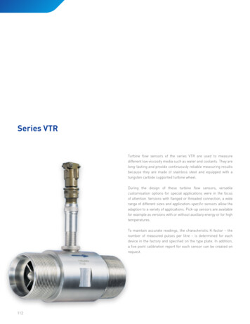
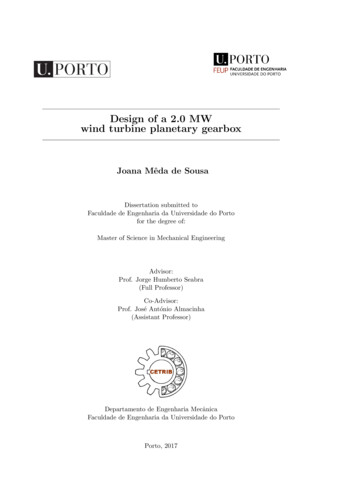
The Following parts are availablPage 4 of 16The Z161X oil filter case fits a (Toyota Land Cruiser).To prepare the filter can, simply cut off the heavy end with a Dremel cutoff wheel, scribe a circle of68mm diameter centered on the other end and cut this out. Measure the inside diameter of the can andnote this. The OD of the diffuser and diffuser cover are sized to fit the case due to possible slightvariations in case size between filter manufacturers.Diffuser The diffuser supplied from the parts list is completely machined and only requires minor finishing, whilethe drawing shows the outer vanes as separate and glued into slots cut in the diffuser body. Use a hightemperature epoxy such as LC3600. After gluing and curing the blades, machine them to fit the case.Then profile the leading edges of both supplied and assembled diffusers as /12/2010
The Following parts are availablPage 5 of 16Compressor coverMade from Aluminum, the cover expands at engine operating temperature to fit tightly into the diffusercover and provide an airtight seal. I ground up a form tool from an old file to shape the radiuses on theprototypes and it worked well. After machining it you can make it pretty by dyeing it using RIT cloth dye.Just follow the instructions on the packet. The prototypes are colored red. You may have to re-machine the mating flange if the cover expands when dyed.Nozzle guide vanesThe drawings provide templates for marking out the slots in both inner and outer rings and for theblades. Glue the templates to the rings using a glue stick, then cut out the slots to the outline on 10
The Following parts are availablPage 6 of 16templates. I first drill a 1mm hole at the end of each slot, then with a cut down DuBro or Dremel heavycut off disc in the Dremel carefully cut the slot until it reaches the drilled holes. Then clean up the endswith a cut down hacksaw blade. Cut out the blades, bend them to the radius, profile them and placethem in the inner slots. Use a hose clamp to keep them aligned in place while brazing the inner ends.After brazing the blades opposite the clamp screw, rotate the clamp 180 deg and then braze theremainder. The brazing only serves to hold them in place while machining the outer diameters. I havehad blades crack at the base after several hours running when they where TIG welded but have had noproblems with simple brazing. To machine the outer sizes, mount the NGV on the shaft tunnel, chuckthe front, put a 608 bearing in the rear end so that it can engage the tail post dead center. With accessto a tool post grinder the blades can be carefully ground to diameter. Otherwise fill between the bladeswith polyester filler to support them and CAREFULLY TAKING SMALL CUTS, turn the outer dimensionsto size. The finished diameter is 0.1mm less than the ID of the turbine shroud while the locating tonguesare sized just less then the OD of the NGV outer. Finally, tap the twelve holes in the NGV outer ring3mm.Combustion chamber I may be wrong, but a lot of machinists are intimidated by any sheet metal work. I'd rather machine atray from solid than try to bend one up from sheet metal. But there was no way around the fact that thegas turbine would take a bit of work with stainless steel sheet. Fortunately, with the purchase of thecombustion chamber pack of parts, most of the hard work is already done. All that remains is rolling,extruding the air holes, and assembling the chamber.The Combustion Chamber AssemblyThis is the heart of the engine and needs to made accurately.There are three stainless cylinderswhich must be formed or rolledinto tubes. the combustionchamber (cc) inner, cc outer, 10
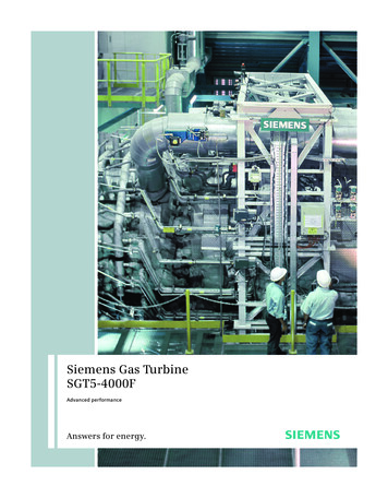
The Following parts are availablPage 7 of 16the outer case. Each of theserequires an overlap seam beformed in the end of the sheet.Note the green plan print whichshows the overlap. This can bedone with a lot of beating with ahammer, or it can be done neatlyand elegantly with a die.I constructed a die from the crsrectangles shown. This is a simplemill-drill job, with the step beingmilled on both sides of the die, sothe steel is shaped into somewhatof a "z" shape when pressed. Ascrap with a successful seam isshow.When you make your die, makeit long enough to do all threeparts. If you size it for just thecombustion chamber, it will betoo short for the case outer wrap!With the seam in place, the trusty(but crusty) grizzly roll came intoplay. This was a lot easier than I) it would be. Rather thanthoughtroll it in one pass, I slowly crept upto the correct diameter throughseveral passes. I was afraid that theroll would press out the seam, butit doesn't hurt the seam too badly.Here, the cc inner is being rolled tothe rather tight diameter required.Ahh, thank goodness for cable ties!I was having a devil of a timewrapping up (and holding) the tubeto the correct diameter for spotwelding of the seam. The idea wasto hold the tube stationary and atthe correct diameter, and thendeliver a couple of preliminarywelds. A pair of cable ties did thejob perfectly. I was even able tocinch the cable tie down rathertightly around the flange spun intothe cc front, shown to the left asthe disk at the bottom.The first spot weld of the seam.Note that I am delivering a singlespot as close to the cc front as Ihttp://sv-precious-moments.com/xbob.htm16/12/2010
The Following parts are availablPage 8 of 16could get. Next, the cc inner wastested for size with the nozzleguide vanes, a portion of whichgrips this from the outer diameterof the tube.After the second spot, the cc innerseam was welded along through itslength.The two larger sets of holes in thecc inner must be swaged out to alarger diameter. The main purposeof the swaging is to create a"crater" in the steel which willinject the air deep into thecombustion chamber. Note that thisis the cc inner, which surrounds theshaft tunnel, and is open throughits middle to pressurized air fromthe compressor output; hence, theholes must be swaged as shown soas to inject the air into thecombustion chamber.I turned a 1/4" square of CRS intothe requiredmale 60 degree cone,)and clamped it into a big boringbar, which I then held in a benchvise. The cc inner hole ispositioned over the punch, and afemale die is used to swage thehole. Note the shape of theresulting swage. Two rows of holesare completed in this fashion in thecc inner tube.Now, we can proceed with weldingthe cc inner to the cc front. I had tomodify my spot welder a bit to getinto the tight confines of this joint.A couple of welds start the process,and then, when alignment isverified, the entire seam is weldedtight. It is important to minimizeair leaks in the chamber seams,especially at the front.The cc outer is produced in muchthe same way as the cc inner,including a set of swaged holes.Once it was sized and seamed, ittoo is welded to the cc front. Stillrequired on the cc outer are 10
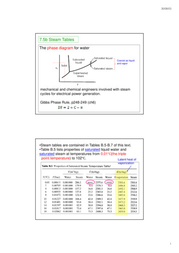
The Following parts are availablPage 9 of 16swirl jets, and the two plug bosses.I plan on using a 1/4 x 32 sparkplug for ignition rather than a gloplug.Here is a cool shot of the actualweld taking place. Each spot weldtakes exactly one second.Overall, the chamber isproceeding nicely, and is actuallya lot easier than I thought it wouldbe.Fuel injection sticks and combustion chamber rearAt the rear of the combustion chamber, held by a diameter of the NGV, are a set of 12 curved SS sticks whichreceive the fuel from the fuel pump via a set of hypodermic needles. The sticks, as well as the combustionchamber (cc) rear, come as part of the cc pack of parts, available from Wren and J.D. Enterprises. These would bedifficult to make, and the pack of parts is highly recommended.The plans call for the sticks to be secured to the cc rear via spot welding, and the front of the sticks form a 54 mmcircle towards the front of the chamber.The sticks as supplied from Wren are close but notexactly to print. Some of) the sticks have more acutebends than others, which makes even positioning ofthe tips on the 54 mm circle difficult. I tried to bendthem a bit more evenly, but once they are in this cutstate, they are almost impossible to bend.Trimming to length is easy, though. I applied a bit ofblue, layed them over the plans, and marked them witha scribe. A fine-toothed hack saw, followed up with abit of sanding, took care of them.It is desireable to have as even a distribution of fuel atthe front of the cc as possible. Rather than guessing, Icreated a thin aluminum jig, with 12 holes drilled onthe desired 54 mm circle. A bit of reaming andfidgeting allowed me to assemble the sticks into thecorrect formation on the cc rear.Wren suggests using four spots per stick flange tosecure the sticks into position. I was not able to getmore than one per stick, and even then I blew 2 verysmall holes in the thin sheet steel. I elected then to sealand secure the flanges to the cc rear with silver braze. Iselected Harris 45 Safety-Silver as the alloy of choice,as it fillets nicely and flows sluggishly at 1370 2/2010
The Following parts are availablPage 10 of 16f. This will provide a more secure joint than a thinner,more fluid braze.The joints are cleaned and wire brushed with astainless brush, soap, and water. I used Harris flux forthe brazing, and applied this material liberally. apiece the size of a lima bean smeared around eachjoint. Apply the flux to all 12 joints, and do the brazingin one sitting.The wire diameter I used was 1/32", and this workedperfectly. A very small propane torch is all that isnecessary, as stainless steel does not conduct heat welland the local area heats quickly. Don't use oxyacetylene, you would surely melt the steel, and it issimply not necessary.The silver braze flowed beautifully around the sticks,and produced a perfect fillet on the underside of thejoint.With the jig removed, the sticks maintain their perfect)and even spacing.On to the swirl jets!The ends are spun over forms although dies could be made to press them out. Save yourself a lot ofwork and order them from the parts list. Templates are provided for the hole layout on outer and innersleeves, just glue them in place with a glue stick, center punch the holes and drill them. I use ordinarytwist drills and have never had any problems. Then swage the holes as per the drawings. Wrap theouter around the two ends, hold in place with hose clamps and mark the join line. I cut it slightlyoversize and chamfer the ends at 45deg so that spot welding the join works. A butt joint can be TIGwelded. Wrap the inner around a mandrel and join as per the outer. The rear end is squared up andspot welded to the outer sleeve, then the vaporizer tubes are brazed in place. They must be straight,and finish at the same distance from the outer sleeve. Silver solder the air jet tubes in place in the frontend, they must be aligned as per the drawing. Spot weld the three SS strips on the rear that locate thefuel manifold. Assemble the shaft tunnel and NGV. The inner sleeve, front face and outer assembly aretrial fitted to this assembly, it must be concentric with the shaft tunnel, and then the front end and innersleeve silver soldered in place. Also silver solder the three locating struts on the outer front and brazethe glow plug fitting in place.Fuel 12/2010
The Following parts are availablPage 11 of 16This must be made and kept perfectly clean internally as the hole sizes are very small and can be easilyblocked. Anneal a length of K&S 1/8” brass pipe by heating it to red and plunging it into water. Bend thetube around a mandrel to achieve the diameter then cut to length leaving a joining gap of 6-8mm. Holdthe circle of tube in place on the rear end of the combustion chamber (the join lies between the holes)and mark it opposite the center of each vaporizer tube for the six needle positions. With the ring on a flatsurface punch holes in the rear side of the tube using a darning needle and a light hammer. Drill the5/32” joiner to take the 3/32” feed tube and silver solder the straight 3/32” tube to both the joiner tubeand fuel fitting. Then silver solder the joiner in place on the ring. Grind the end of the hypo needles asshown in the drawings and insert each one in the tube with the angled face facing the direction of fuelflow. That’s three one way and three the other. Screw a Festo fitting (PN 12255) into the fuel feed fittingand attach a length of fuel tube to it. Stick the other end in your mouth and blow gently while silversoldering the needles in place. This pressure will prevent the silver solder and flux getting into andblocking the needle and or tube. When completed place the manifold in water and blow and ensure allneedles are clear. Next is to hook the fuel manifold up to the LPG start gas bottle and just slightly, veryslightly crack the valve open. Light each needle and ensure that the flames from each are of equallength. Any needles showing a low flame should be removed and checked. Pressurize the fuel manifoldwith lung pressure while heating the needle joint to remove it. Check the angle on the end of a newneedle and solder it in place, then repeat the testing procedure. THIS MUST BE DONE PROPERLY.Finally lay a 5mm drill shank against each needle and bend each in turn around it so that they pointforward into the vaporizer tubes where the needle ends must touch the inner face.BalancingFor high performance running it is essential that the rotor (shaft, bearings, spacers and wheels) arebalanced. Hand balancing is just not good enough. A turbo charger repair center should be able tobalance your rotor, suggest that they use the T6 settings and get better a than 50 milligrams/cm result(20mg/inch). Once your rotor is balanced, mark each) part with an indent so that it is always assembledthe same as it was balanced. Note than any radial clearance between the wheels and shaft may resultin the balance changing when the rotor is re-assembled. To prevent this happening balance the rotorwith the rear bearing installed and do not disassemble the turbine end before fitting to the engine. Forthe compressor, a slight interference fit that requires heating the wheel to install it will minimize anyunbalance. Here is a link to build a balancer. If You want to balance it your self and are going to makeseveral engines you might want to follow this link and build your own lace the diffuser on the shaft tunnel and mark and drill the 2.5mm holes in the shaft tunnel, then tapthem 3mm. Drill the six 2.5mm and two 2mm diameter holes through the diffuser wedges, hold thediffuser cover in place on the diffuser, it must be concentric so use a hose clamp around the outside ormachine and use a centering mandrel. Drill the eight holes back through the diffuser into and throughthe cover. Tap the 2.5mm holes in the diffuser 3mm and open out the 2.5mm holes in the cover to3.1mm. Drill out the 2mm holes in the cover to 4.2mm and tap them 5mm. Screw the two Festo fittinginto the cover and grind away the excess so they are flush with the rear face of the cover. Remove thetwo fittings and assemble them with the 1.5mm tubing as detailed in the drawings making sure they arenot blocked. Assemble the compressor and diffuser cover and check that there is no lip at the rear facewhere they meet. Machine the compressor cover to remove any lip. Also file the cover away to provideclearance for the lubrication and case pressure fittings. Position the NGV inner on the shaft tunnel andmark, drill and tap the six holes in the tunnel. Place the turbine shroud in the cutout on the back of thecase and using it as a template drill the case holes to 3mm. Remove the shroud and open up the caseholes to 3.2mm. CLEAN ALL SWARF FROM ALL PARTS. Assemble the diffuser to the shaft tunnel.Lightly oil the bearings, then place the rear bearing (the one with no cage) with the thicker inner ring 0
The Following parts are availablPage 12 of 16the rear on the shaft, then the spacer and turbine wheel and tighten the nut. Put the wave washer intothe front of the shaft tunnel, then the “O” ring, push the bearing in place and push the shaft into placefrom the rear. Place the compressor spacer and compressor and tighten the compressor nut. Do notover tighten the nuts. The shaft should spin without binding and should rotate for about four secondswith a spin of the compressor nut with your fingers. Any less than this and the preload is too high.Check that the outer front edge of the compressor wheel lines up with the face of the diffuser. Behind isa NO slightly in front is OK, but flush is best. The preload and compressor wheel alignment are adjustedby means of 8mm x 12.5mm shims behind or in front of the front bearing for preload adjustment and ifthe compressor wheel is behind the diffuser. If the wheel is forward of the diffuser the compressorspacer thickness needs to be reduced. If the spacer thickness is reduced the faces must be finishedABSOLUTELY PARALLEL otherwise you will do very expensive bearings in. Install the compressorwheel cover and again check that the shaft spins freely and there is not excessive clearance (greaterthan 0.2mm) between the wheel and cover. See the how to fix it panel if there is. Once the alignmentand preload is OK remove the shaft and front bearing. Attach the NGV inner to the shaft tunnel, slidethe NGV outer ring in place and slide the lot into the case. Put the front bearing in place and slide theshaft into place then assemble the turbine shroud to the case and NGV outer ring with the twelve 6mmlong cap head screws. Using a pair of tin snips cut the front of the case off so it finishes flush with thecompressor cover. Mark out equally around the case forward of the “O” ring slot and drill the twelve1.6mm holes then tap them 2mm and install the cap head screws. Check that the shaft spins freely andwith pretty equal clearance between the turbine wheel and turbine shroud. If there is unequal clearanceand all the parts have been accurately made then place the assembly face down on a block of woodwith the shaft extending through a drilled hole so that it takes no load. Using a soft drift, copper oraluminum and a hammer, strike the turbine shroud flange on the smaller clearance side to slightly bendthe case rear face to align it. Undo the case screws and then remove the shaft and assembly from thecase. Make indent marks on the Tunnel, NGV inner and outer, turbine shroud, case and diffuser coverso that they can always be reassembled in the same alignment. Remove the diffuser from the shafttunnel and then assemble the fuel manifold to the combustionchamber. Make a slight “S” bend in the)straight fuel line ensuring that it does not cover any air holes in the outer sleeve. Assemble the chamberto the NGV and slide the lot back into the case and install the turbine shroud. Measure the position ofthe glow plug and fuel fittings, remove the assembly and drill the case at the measured positions.Measure forward from the glow plug hole for the gas fitting and silver solder a 5mm nut in position, thendrill 4mm through the nut and tap 5mm through the case. Cut the threads from a DuBro pressure fittingand silver solder it in the center at the bottom of the case. Drill through the fitting and through the case.Disassemble and remove all burrs and swarf from the case both inside and out and the sharp front edgethat was cut with the tin snips. For a pretty engine get the case chrome plated.Final assembly.Assemble the diffuser and it’s cover. Screw the lubrication assembly into place and bend the tube sothat the needle lies in a slot in the diffuser rear face. Bend the needle so that it lies freely in the slot andis not loaded when the tunnel is assembled. Cut a small strip of aluminum, place it over the tube anddrill and tap it 2mm so that it clamps the line in place. Install the screws and grind off any excess thatprotrudes through the front face of the diffuser. Screw the case pressure fitting in place, it should extendjust past the diffuser rear face. Blow through both fittings to ensure they are not blocked. REMOVE ANYSWARF. Install the “O” ring, wave washer and the oiled front bearing as well as any shims needed inthe shaft tunnel. Assemble the turbine end of the shaft and use some anti seize compound on thethread before tightening the nut. Assemble the tunnel and NGV, oil the rear bearing and install the shaft.Smear a light and even film of exhaust seal compound on the rear face of the NGV outer flange. Insertthe assembly into the case and install the turbine shroud using shims placed between the turbine wheelouter and shroud to keep it all centered and evenly tighten the twelve did indent mark it right, because6mm long cap head screws. Slide the combustion chamber into place in the case, ensuring that itengages with the NGV and install and tighten the glow plug. Check that the chamber is centered withinthe case, you can bend and adjust the three struts to center it. This is very important. Install the 10
The Following parts are availablPage 13 of 16fitting. Use an annealed copper washer on the fuel fitting and a small amount of plumbers thread sealingtape on the thread then install the fitting. Hold the brass fitting inside the case with a spanner andsecurely tighten the fuel fitting. IT IS VITALLY IMPORTANT THAT THERE ARE NO LEAKS IN THISASSEMBLY. Install the case sealing “O” ring, then screw the diffuser with compressor cover to thetunnel, you remember the twelve tapped holes around the outside. Do they line up? Assemble thecompressor spacer, shims if required and compressor wheel, use some anti seize on the thread andlightly tighten the compressor nut. Remove the screws used to hold the diffuser and cover together,install the compressor cover and install and tighten the 12mm long cap heads that hold the lot together.Finally install the twelve 2 x 6mm long screws in the front end of the case. Remove the glow plug andusing a pin pull carefully out the element so that it extends past the end of the plug. Then reinstall theglow plug, check that the shaft spins freely and it’s run time. Note that the tailbone has not beeninstalled as yet, we leave this until after the initial running as without it the EGT is a bit lower.How to fix thingsTurbine wheel rubs. There are two reasons why the turbine is not concentric within the shroud. The rearend of the engine must be made accurately, to size, concentric and with no loose fits. The clearancebetween the NGV blades and outer should be no more than 0.05mm, that’s 0.1mm in diameter. The68mm diameter hole in the end of the case must be in the center. Also the case is slightly domed andthis is flattened out when the twelve NGV assembly screws are tightened. Therefore the screws must betightened evenly and also ensure there is no swarf from the hole drilling left inside the case.Compressor wheel clearance. For maximum efficiency the wheel to cover clearance should not exceed0.1mm. While the engine will run at greater clearances, this will be at the expense of a higher EGT andincreased fuel consumption. To improve a loose fit, make up a thick paste of high temperature epoxyand micro balloons. Coat the inside of the cover with this paste and allow it to cure. Assemble the shafttunnel and diffuser, fit standard 608 bearings and installthe shaft. (Don’t use your expensive ceramic)bearings for this operation). Push the compressor cover into place and then turn the shaft from theturbine end using the turbine wheel as a handle. The compressor wheel will leave a mark on high spotson the inside of the cover. Sand them away and keep repeating the process until a good fit is obtained.Then bolt the cover in place and spin the shaft from the rear using a model engine starter to exertforward pressure on it. Ensure the compressor wheel does not rub. When happy with the fit,disassemble the engine and blow out any dust, then reassemble as per the instructions.Modifications from early drawingsVaporizer tube length increased to 64mm Air jets at front are not flared and point between center andouter edge of vaporizer tube but still in plane and moved rearwards to locate in outer wrapper justbehind front end flange. NGV is held to shaft tunnel with six screws. Shaft tunnel rear flange to attachNGV is moved back by 2mm. Glow plug and gas fitting now located above a vaporizer tube.Running the EngineAssembling the engine was described so now we will turn our attention to the exciting bit, starting it. Torun the engine you need, a test stand, fuel/oil, an electric fuel p
BUILD YOUR OWN RC TURBINE ENGINE By Bob Englar This Turbine engine is “state of the art” as it currently applies and is designed to deliver high power with reliability. While using the same compressor and turbine wheels as in the KJ66 design, it is si