Transcription
GAS TURBINEPOWER PLANTSProf. A. Valentini
INTRODUCTIONI have written these notes for Italian speaking students in the last year of high school forthe course of Applied Mechanics and Fluid Machinery. The main aim is to give them thechance to follow one module of their mechanics course all in English. The knowledge ofbasic thermodynamics studied during the fourth year of school is assumed, however,revision of the main concepts concerning gas turbo machinery is included in the first twochapters.Some exercises, that I will solve with the students during the course, are included as wellas all the mathematical demonstrations that they are able to understand with their presentmathematical knowledge.I hope that my work will be useful for improving the students' speaking, understanding andreading abilities in both technical and everyday English.Prof. A. Valentini - Gas Turbine Power Plants1
CONTENTS1 FIRST LAW OF THERMODYNAMICS FOR AN OPEN SYSTEMpag. 32 THE ISENTROPIC EFFICIENCY FOR GAS TURBO MACHINERYpag. 53 GENERALITIES ABOUT GAS-TURBINE POWER PLANTSpag. 74 THE JOULE CYCLEpag. 105 THE REAL CYCLEpag. 126 THE COMBUSTION CHAMBERpag. 157 TURBINE PLANTS WITH REGENERATIVE INNER HEAT EXCHANGERpag. 168 CYCLES WITH INTER COOLING AND REHEATINGpag. 18EXERCISESpag. 20BIBLIOGRAPHYpag. 24Prof. A. Valentini - Gas Turbine Power Plants2
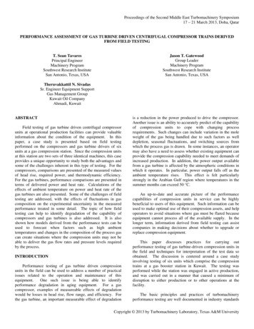
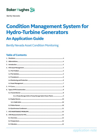
1 FIRST LAW OF THERMODYNAMICS FOR AN OPEN SYSTEMThermodynamic systems can be open, if they exchange mass with external environment,or closed if they don't exchange mass. They usually exchange energy as mechanicalenergy (work) and/or thermal energy (heat), if the system doesn't exchange mass andenergy it is called isolated. Gas turbine and turbo compressors are open systems socalculations are done with the first law of thermodynamics for an open system:𝐿𝑖 𝑄𝑒 𝑖 𝐸𝑘 𝐸𝑔 𝐿𝑖(1)internal work (it is the mechanical energy exchanged between the gas andthe blades of the turbine) 𝑄𝑒heat exchanged through control volume 𝑖change in enthalpy between the outlet and inlet of the machine 𝐸𝑘change in kinetic energy 𝐸𝑔change in potential energyAll the terms in equation (1) are measured in𝐽𝑘𝑔(energy per mass unit). Figure 1 shows apicture of a gas turbine.fig. 1 - Gas turbineWe consider, by convention, the work and the heat coming into the system as positive andthe work and the heat coming out as negative.Prof. A. Valentini - Gas Turbine Power Plants3
Equation (1) can be simplified: Since turbo machines are so fast heat transfer is insignificant so 𝑄𝑒 0 For gases the change in potential energy is small in comparison with the change inenthalpy so 𝐸𝑔 0 Normally the change in kinetic energy between the inlet and outlet gas is small andso 𝐸𝑘 0.We consider all gases to be perfect (or ideal) so the perfect gas equation (2) is alwaystrue.𝑃 𝑣 𝑅 𝑇(2) 𝑃gas pressure (𝑃𝑎 ) 𝑣specific volume ( 𝑘𝑔 ) 𝑅individual gas constant depending on its molecular weight ( 𝑘𝑔 𝐾) 𝑇gas temperature (𝐾)𝑚3𝐽𝐽For perfect gases the enthalpy is the product of pressure specific heat of the gas 𝐶𝑝 (𝐾 𝑘𝑔)and the temperature 𝑇 (𝐾) so equation (1) becomes:𝐿𝑖 𝐶𝑝 𝑇(3)For the sign convention mentioned above the work calculated with (3) is positive for acompressor and negative for a turbine. For turbines we defined the positive "internal workobtained " (𝐿𝑖 )𝑜𝑏𝑡 𝐿𝑖 . The mechanical power produced by a turbine and that absorbedby a turbo compressor are calculated by equations (4) and (5) respectively:𝑇𝑃𝑇 𝐺. (𝐿𝑖 )𝑜𝑏𝑡 𝜂𝑚𝑃𝐶 𝐺 𝐿𝑖𝐶𝜂𝑚(4)(5)𝑇𝐶Where 𝐺 is the mass flow rate and 𝜂𝑚and 𝜂𝑚are the mechanical efficiencies of the twoturbo machines. Mechanical efficiencies take into consideration the work lost bymechanical friction and they are quite high (𝜂𝑚 0.96 0.99).In table 1 the main constants for some gasses are included.Prof. A. Valentini - Gas Turbine Power Plants4
𝑪𝒑𝑪𝑽𝑪𝒑𝑪𝑽𝑹 𝑪𝒑 𝑪𝑽(𝐽/𝑘𝑔 𝐾)(𝐽/𝑘𝑔 𝐾)(𝐽/𝑘𝑔 .32CH4225317355181.3𝒌 tab. 1 - Table of gas constants2 THE ISENTROPIC EFFICIENCY FOR GAS TURBO MACHINERYAs we said before turbo machines are adiabatic, if the thermodynamic transformation ofthe gas in the machines was reversible it would be isentropic. Since the fluid-dynamicfriction can never be neglected in fast machines, the real thermodynamic transformation isirreversible with increasing entropy. The isentropic efficiency compares a real machinewith an ideal one. Il figure 2 are represented the real (irreversible) and ideal (reversible)transformations for turbines and turbo compressors in temperature-entropy expansion22idSSfig. 2 Thermodynamic transformations of the gas in turbo compressors and turbinesProf. A. Valentini - Gas Turbine Power Plants5
The isentropic efficiencies are defined as below:turbo compressor𝑃2compression ratio𝑃𝛽𝑐 𝑃2𝐶𝜂𝑖𝑠1𝐿𝑖𝑑𝑖 𝐿𝑖(7)𝑃1gas turbine𝑃1𝑇𝜂𝑖𝑠 expansion ratio𝑃𝛽𝑒 𝑃1(𝐿𝑖 )𝑜𝑏𝑡(𝐿𝑖 )𝑖𝑑𝑜𝑏𝑡(8)2𝑃2The compression and expansion ratios are usually between 15 and 40 or sometimesmore.It is useful to remember the equation for isentropic transformations studied in generalthermodynamics:𝑝 𝑣 𝑘 𝑐𝑜𝑛𝑠𝑡𝑎𝑛𝑡with 𝑘 (9)𝐶𝑃𝐶𝑉If we combine (9) with (2) we get:𝑇𝑘 𝑐𝑜𝑛𝑠𝑡𝑎𝑛𝑡𝑝𝑘 1(10)The real transformation in a turbo machine can be considered a polytropic transformation:𝑝 𝑣 𝑚 𝑐𝑜𝑛𝑠𝑡𝑎𝑛𝑡(11)Where the 𝑚 is exponent of the polytropic.Prof. A. Valentini - Gas Turbine Power Plants6
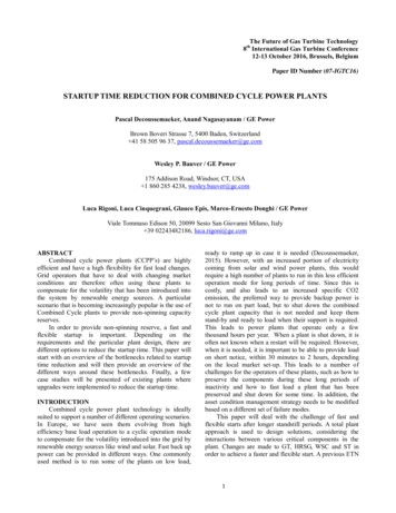
3 GENERALITIES ABOUT GAS-TURBINE POWER PLANTSThe purpose of gas-turbine power plants is to produce mechanical power from theexpansion of hot gas in a turbine. In these notes we will focus on stationary plants forelectric power generation, however, gas turbines are also used as jet engines in aircraftpropulsion. The simplest plant is the open turbine gas cycle used to produce electricalpower as shown in figure 3.1 . Compressor2 . Generator3 . Fuel flow control4 . Combustion chamber5 . Fuel nozzle6 . Mixing tube7 - Electrical starter8 - Turbinefig. 3 - Open turbine gas cycleThe net power available on the shaft is transformed into electrical power by the generatorwhile the electrical starter is an electrical engine which is only used when the plant isturned on. The schematic picture of the previous plant, non including electrical starter andgenerator, is shown in figure 4.Gb (fuel mass flow rate)combustionchamber2turbocompressor3shaftPU (net mechanical power)turbine41Ga Gb (exhaust gases mass flow rate)Ga (air mass flow rate)fig. 4 - Open turbine gas cycleProf. A. Valentini - Gas Turbine Power Plants7
Air at room pressure and temperature is compressed to a high pressure in the turbocompressor Fuel is added in the combustion chamber where combustion takes place resulting inhigh-temperature combusted gases The hot gases expand in the turbine back to the atmospheric pressure producingmechanical power.The cycle is said to be open because fresh air enters the compressor continuously andexhaust is expelled, but thermodynamically it is as if the operating fluid returns to its initialstate. Part of the mechanical power generated by the turbine is used to drive thecompressor.An alternative plant is the so called closed turbine gas cycle, schematically shown in figure5.Gb (fuel mass flow rate)Ga (air mass flow rate)2Ga Gb (exhaust gas mass flow rate)3PU41G(operating fluid mass flow rate)Gr (refrigerator mass flow rate)fig. 5 - Close turbine gas cycleIn this case the operating fluid does not undergo any chemical transformations (because itis not involved in combustion processes) but only thermodynamic transformations.Combustion takes place between air and fuel in the combustion chamber, which is also aheat exchanger. Both plants have advantages and disadvantages. In the first case it is notnecessary to cool down the operating fluid (this requires a huge amount of refrigeratorProf. A. Valentini - Gas Turbine Power Plants8
mass flow rates) and so this plant can be adopted on sites with low water availability. Oneof the advantages of the closed turbine gas cycle is that the turbine stays clean becausethe combustion products do not pass through it. Another advantage is that it is possible touse gases with 𝑘 𝑘𝑎𝑖𝑟 (𝑘𝑎𝑖𝑟 1.4), which increases the efficiency of the cycle (as we willsee in the next chapter).The net power available on the shaft in both cases is:𝑃𝑈 𝑃𝑇 𝑃𝐶(12)and it can be transformed into electric power (𝑃𝑒𝑙 ) by an electrical machine called a turboalternator:𝑃𝑒𝑙 𝑃𝑈 𝜂𝑒𝑙(13)where 𝜂𝑒𝑙 is the electrical efficiency of the alternator.The thermal power produced by the combustion of the fuel is:𝑄̇1 𝜂𝑏 𝐺𝑏 𝐻𝑖(14)where 𝜂𝑏 and 𝐻𝑖 are the combustion efficiency and the inferior calorific value of the fuel.The thermal efficiency (how heat is transformed in work) of the plant is:𝜂𝑢 𝑃𝑈𝑄̇1(15)and the total efficiency of the electrical power transformation is:𝜂𝑡𝑜𝑡 𝑃𝑒𝑙𝑄̇1 𝜂𝑢 𝜂𝑒𝑙(16)We will only consider the open-turbine-gas-cycle plant in these notes since they are themost common type.Prof. A. Valentini - Gas Turbine Power Plants9
4 THE JOULE CYCLEThe Joule (or Brayton-Joule) cycle, shown in figure 6, is the ideal cycle for gas-turbineengines. The ideal cycle is made up of the following four reversible processes: 1-2 Isentropic compression 2-3 Constant pressure combustion 3-4 Isentropic expansion 4-1 Constant pressure heat rejectionT3P2 P3214P1 P4Sfig. 6 - The Brayton - Joule cycle in T-S chartThe efficiency of the ideal Joule cycle can easily be calculated assuming that in idealcycles just one kilo of fluid, that undergoes only thermodynamic transformations, isconsidered. Therefore, the (15) can be written in terms of energy as below:𝜂𝑢 𝐿𝑈(𝐿𝑇 )𝑜𝑏𝑡 𝐿𝐶 𝑄1𝑄1(17)The terms of the fraction can be calculated with the first law of thermodynamics for opensystems:(𝐿𝑇 )𝑜𝑏𝑡 𝐶𝑃 (𝑇3 𝑇4 )(18)𝐿𝐶 𝐶𝑃 (𝑇2 𝑇1 )(19)𝑄1 𝐶𝑃 (𝑇3 𝑇2 )(20)If we put (18), (19) and (20) in (17), and simplify the specific heat, we get:Prof. A. Valentini - Gas Turbine Power Plants10
𝜂𝑢 (𝑇3 𝑇4 ) (𝑇2 𝑇1 )𝑇3 𝑇2(21)(21) can be rearranged as follow:𝑇𝑇1 (𝑇4 1)(𝑇3 𝑇2 ) (𝑇4 𝑇1 )(𝑇4 𝑇1 )1𝜂𝑢 1 1 𝑇3𝑇3 𝑇2𝑇3 𝑇2𝑇2 (𝑇 1)2but using (10) for the isentropic compression and expansion we see that(22)𝑇4𝑇1 𝑇3𝑇2so (22)becomes:𝜂𝑢 1 𝑇1𝑇2(23)using (10) again we get:𝑇2𝑃2 ( )𝑇1𝑃1𝑘 1𝑘 𝛽𝐶𝑘 1𝑘(24)so (22) becomes:𝜂𝑢 1 1(25)𝑘 1𝛽𝐶 𝑘Therefore, the efficiency of the ideal cycle depends on the type of gas (though theconstant 𝑘) and the compression ratio and it increases if 𝑘 and/or 𝛽𝐶 increase. In figure 7the plot of the efficiency versus the compression ratio (with 𝑘 fixed) can be seen.𝜼𝒖10.90.80.70.60.50.40.30.20.10𝒌 𝟏. 𝟒020406080𝜷𝑪100fig. 7 - Graph of the thermal efficiency versus the compression ratio for the ideal cycleProf. A. Valentini - Gas Turbine Power Plants11
5 THE TRUE CYCLEIn gas turbine power plants the true cycle is quite different from the ideal Brayton-Joule,which was described in chapter 4, due to the following fluid dynamics and mechanicallosses: compression and expansion are not isentropic pressure drop in the combustion chamber variation of average gas parameters (caused mainly by temperature variation) imperfect combustion bearing friction drive power of auxiliary equipmentWe consider the non-isentropicity in the thermodynamic transformation in the turbomachines using the isentropic efficiencies (7) and (8).To consider the pressure drop in the combustion chamber we define the pneumaticcombustor efficiency as:𝜂𝜋𝑏 𝑃3𝑃2(26)were 𝑃2 is the turbo-compressor outlet pressure and 𝑃3 is the combustor outlet pressure.The pneumatic combustor efficiency in smaller than one, as are all efficiencies, and so thetrue cycle expansion ratio is smaller than the compression ratio𝛽𝑐 𝛽𝑒 𝑃2𝑃1(27)𝑃3 𝜂𝜋𝑏 𝑃2 𝜂𝜋𝑏 𝛽𝑐𝑃4𝑃1(28)In these notes we do not consider the variation of gas parameters so some average valuesare assumed. Imperfect and incomplete combustion are considered assuming acombustion efficiency 𝜂𝜋𝑏 , while mechanical friction (and the drive power of auxiliaryequipment, if present) is considered assuming the mechanical efficiencies of the two turbo𝑇𝐶machines 𝜂𝑚and 𝜂𝑚.The variations with respect to the ideal cycle are shown in figure 8.Prof. A. Valentini - Gas Turbine Power Plants12
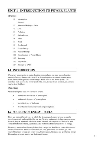
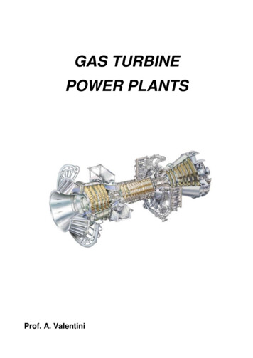
TT33idP33P22id2144idP1 P4Sfig. 8 - The true Joule cycle in T-S chartThe mechanical power produced by the turbines in this case can be written as:𝑇𝑇𝑃𝑇 (𝐺𝑎 𝐺𝑏 ). (𝐿𝑖 )𝑜𝑏𝑡 𝜂𝑚 (𝐺𝑎 𝐺𝑏 ). 𝐶𝑝 (𝑇3 𝑇4 ) 𝜂𝑚(29)While the power absorbed by the compressor is:𝑃𝐶 𝐺𝑎 𝐶𝑝 (𝑇2 𝑇1 )𝐺𝑎 𝐿𝑖 𝐶𝐶𝜂𝑚𝜂𝑚(30)Approximately 55 to 65 percent of the power produced by the turbine is used to drive thecompressor.The plant thermal efficiency (15) can be written as follow:𝑃𝑈𝜂𝑢 𝑄̇1𝑇(𝐺𝑎 𝐺𝑏 ) 𝐶𝑝 (𝑇3 𝑇4 ) 𝜂𝑚 𝐺𝑎 𝐶𝑝 (𝑇2 𝑇1 )𝐶𝜂𝑚𝜂𝑏 𝐺𝑏 𝐻𝑖(31)For the true cycle the efficiency strongly depends on the gas turbine inlet temperature 𝑇3 ,higher temperatures lead to higher efficiency as shown in figure 9.Prof. A. Valentini - Gas Turbine Power Plants13
𝜼𝒖0.30.250.2𝑻𝟑 𝟏𝟓𝟎𝟎 𝑲0.150.1𝑻𝟑 𝟏𝟐𝟎𝟎 𝑲0.05𝑻𝟑 𝟖𝟎𝟎 𝑲𝑻𝟑 𝟏𝟎𝟎𝟎 𝑲00102030405060𝜷𝑪70fig. 9 - Graph of thermal efficiency versus compression ratio and temperature T3Turbine inlet temperature is limited by the thermal conditions that can be tolerated by themetal alloy of the turbine blades. Gas temperatures at the turbine inlet can be between1200ºC and 1400ºC, but some manufacturers have been able to boost inlet temperaturesas high as 1600ºC by engineering blade coatings and cooling systems to protectmetallurgical components from thermal damage.Prof. A. Valentini - Gas Turbine Power Plants14
6 THE COMBUSTION CHAMBERAs we already know the combustion chamber (or combustor or burner) is the componentin a gas turbine power plant where combustion takes place. The picture of a typicalcombustor is shown in figure 10.fig. 10 - Main parts of a combustion chamberThe energy balance in a combustio
7 TURBINE PLANTS WITH REGENERATIVE INNER HEAT EXCHANGER pag. 16 8 CYCLES WITH INTER COOLING AND REHEATING pag. 18 EXERCISES pag. 20 BIBLIOGRAPHY pag. 24 . Prof. A. Valentini - Gas Turbine Power Plants 3 1 FIRST LAW OF THERMODYNAMICS FOR AN OPEN SYSTEM Thermodynamic systems can be open, if they exchange mass with external environment, or