Transcription
General documentationTechnical descriptionWind turbine class Nordex Delta4000N149/4.0-4.5E0004109668Revision 08 / 2019-11-29- Translation of the original document (E0004051131 rev. 08) This is a translation of the original German document. In case of doubt, the German text shall prevail.Document will be distributed electronically.Original document at Nordex Energy GmbH, Engineering. 2019 by Nordex Energy GmbH
This document was created by Nordex Energy GmbH and/or an affiliated company asdefined in section 15 et seq. of the German Stock Corporation Act (AktG).This document, including any presentation of its contents in whole or in parts, is theintellectual property of Nordex Energy GmbH and/or affiliated companies within the meaningof section 15 et seq. of the German Stock Corporation Act (AktG). The information containedin this document is confidential and must never (not even in extracts) be disclosed to thirdparties without the prior written approval of Nordex Energy GmbH.All rights reserved.Any disclosure, duplication, translation or other use of this document or parts thereof,regardless if in printed, handwritten, electronic or other form, without the explicit approval ofNordex Energy GmbH is prohibited.Copyright 2019 by Nordex Energy GmbH.ContactIf you have questions about this documentation, please contact:Nordex Energy GmbHLangenhorner Chaussee 60022419 HamburgGermanyPhone: 49 (0)40 300 30 -1000Fax: 49 (0)40 300 30 e.com 2019 by Nordex Energy GmbH
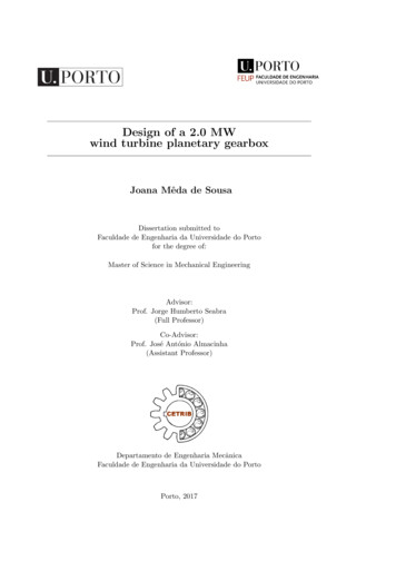
General documentation1.Revision 08 / 2019-11-29StructureThe Nordex N149/4.0-4.5 wind turbine (WT) is a speed-variable wind turbinewith a rotor diameter of 149 m and a nominal power between 4000 and 4500 kW(project-specific up to 4800 kW) which can be adapted dependent on location.The wind turbine is designed for class S in accordance with IEC 61400-1 or windzone S in accordance with DIBt 2012 and is available in 50 Hz and 60 Hzvariants.A Nordex N149/4.0-4.5 wind turbine consists of the following main components: Rotor, with rotor hub, three rotor blades and pitch system. Nacelle with drive train, generator, yaw system, medium voltage transformerand converter. Tubular tower or hybrid tower with MV switchgear.1.1TowerA N149/4.0-4.5 class wind turbine can be erected on a tubular steel tower or ona hybrid tower. The steel tower is cylindrical and consists of several sections.This tower is bolted to the anchor cage embedded in the foundation. The bottompart of the hybrid tower consists of a concrete tower and the top part of a tubularsteel tower with two sections.Corrosion protection is guaranteed by a coating system of the surface accordingto ISO 12944. A service lift, the vertical ladder with fall protection system as wellas resting and working platforms inside the tower allow for a weather-protectedascent to the nacelle.652341Fig. 114Overview of the bottom section in a tubular steel tower, tower plates notshownTower accessTower service lift25MV switchgearLadder pathE000410966836Control cabinetFlange platformPage 3 of 22
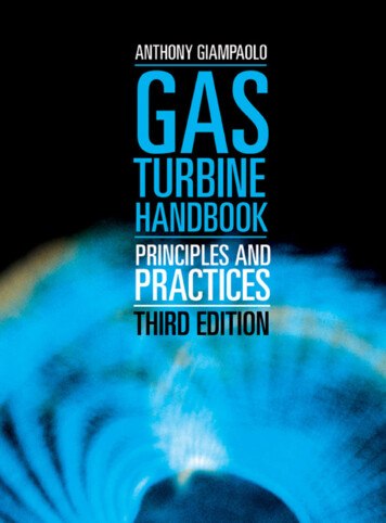
Revision 08 / 2019-11-29General documentationThe foundation structure of all towers depends on the soil conditions at theintended location.1.2RotorThe rotor consists of the rotor hub with three slewing bearings, the pitch systemfor blade adjustment and three rotor blades.The rotor hub consists of a base element with support system and spinner. Thebase element consists of a stiff cast structure, on which the pitch bearings andthe rotor blades are assembled. The rotor hub is covered with the spinner whichenables the direct access from the nacelle into the rotor hub.The rotor blades are made from high quality fiber glass- and carbon-fiberreinforced plastic. The rotor blade is tested statically and dynamically inaccordance with the guidelines IEC 61400-23 and DNVGL-ST-0376 (2015).Optionally the blades can be equipped with serrations to optimize the noise level.The serrations consist of several serrated light-gray components made fromglass fiber laminate, with a length of approx. 0.3 m to approx. 0.7 m, which areattached to the trailing edge of the rotor blades.Fig. 2Serrations on a rotor blade's trailing edgeThe pitch system serves to adjust the pitch angle of the rotor blades set by thecontrol system. For each individual rotor blade the pitch system comprises anelectromechanical drive with 3-phase motor, planetary gear and drive pinion, aswell as a control unit with frequency converter and emergency power supply.Power supply and signal transfer are realized through a slip ring in the nacelle.1.3NacelleThe nacelle contains essential mechanical and electric components of the windturbine. The nacelle can be pivoted on the tower.The transformer converts the generator/converter system's low voltage to themedium voltage defined by the point of supply.In the switch cabinet, all electrical components required for the control andsupply of the turbine are located.With the mechanical rotor brake the rotor is locked during maintenance work.For this, a sufficient oil pressure is generated by the hydraulic pump.Page 4 of 22E0004109668
General documentationRevision 08 / 2019-11-29The converter connects the electrical grid to the generator which means thegenerator can be operated with variable rotational speeds.The gearbox increases the rotor speed until it reaches the speed required forthe generator.The bearings and gearings are continuously lubricated with oil. A 2-stage pumpenables the oil circulation. A combination filter element with coarse, fine andultrafine filter retains solid particles. The control system monitors thecontamination of the filter element.The gear oil used for lubrication also cools the gearbox. The temperatures of thegearbox bearings and the oil are continuously monitored. If the optimumoperating temperature is not yet reached, a thermal bypass directs the gear oildirectly back to the gearbox. If the operating temperature of the gear oil isexceeded it is cooled down.The gearbox cooling is realized with an oil/water cooler that is installed directlyat the gearbox. The cooling water is re-cooled together with the cooling waterfrom the generator, converter and transformer in a passive cooler on the roof ofthe nacelle.The rotor shaft is supported in the rotor bearing inside the nacelle. A rotor lockis integrated in the rotor bearing, with which the rotor can be reliably locked inplace mechanically.All nacelle assemblies are protected against wind and weather conditions bymeans of a nacelle housing.The coupling acts as force-transmitting connection between the gearbox andthe generator.The generator is a 6-pole doubly-fed induction machine. An air/water heatexchanger is mounted on the generator. The cooling water is re-cooled togetherwith the cooling water of the other major components in a passive cooler on theroof of the nacelle.The yaw drives optimally rotate the nacelle into the wind. The yaw drives arelocated on the machine frame in the nacelle. A yaw drive consists of an electricmotor, multi-stage planetary gear, and a drive pinion. The drive pinions meshwith the external teeth of the yaw bearing. In the aligned position the nacelle islocked with the yaw drives.E0004109668Page 5 of 22
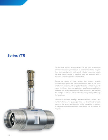
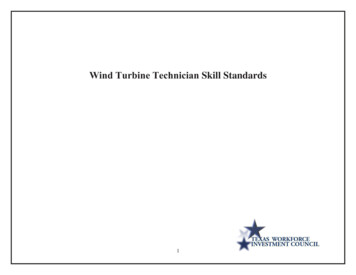
Revision 08 / 2019-11-29General documentation2435867110911Fig. 3147101.4Schematic diagram of the nacelle, exampleTransformerConverterRotor bearingGenerator25811CabinetGearboxNacelle housingYaw drives369Rotor brakeRotor shaftCouplingAuxiliary systemsGenerator bearing, gearing of the pitch bearings, rotor shaft and gearing of theyaw bearing are each equipped with an automatic lubrication system. Anautomatic lubrication of the raceways of the pitch bearing can be offered as anoption.Gearbox, generator, cooling circuit and all relevant switch cabinets are equippedwith heaters.An electric chain hoist is installed in the nacelle which is used for lifting tools,components and other work materials from the ground into the nacelle.A second, movable overhead crane is used for carrying the materials within thenacelle.Various options of additional equipment are available for the wind turbine.Cooling systemGearbox, generator, converter and transformer are cooled via a coupled air/water heat exchanger. A pump conveys the mixture through the heat exchanger.At startup the lightly heated gear oil is directly fed back into the gearbox via athermal bypass and only directed into the plate-type heat exchanger afterreaching operating temperature.Page 6 of 22E0004109668
General documentationFig. 4Revision 08 / 2019-11-29Diagram of the cooling of major components in the nacelleHeat exchange takes place via two passive coolers on the nacelle roof.132Fig. 51Passive coolerPassive coolers in a frame on the roof2NacelleE00041096683Rear roofPage 7 of 22
Revision 08 / 2019-11-292.General documentationMedium-voltage switchgearThe medium voltage components are used to connect a WT to the wind farmmedium-voltage grid or the local grid operator. The tower base contains the MVswitchgear. It consists of a transformer field with circuit breakers and at leastone ring cable field as default and up to three ring cable fields as an option(dependent on the wind farm configuration). The transformer panel consists of avacuum circuit breaker and the disconnector with ground switch. The ring cablepanel consist of a switch disconnector with a ground switch. The entire MVswitchgear is assembled on a support/adapter frame.Further characteristics of the MV switchgear: Routine tests of each switchgear in compliance with IEC 62271-200 Type tested, SF6 insulation Internal switchgear for self-contained electrical systems (min. IP2X) SF6 tank: metal-clad, metal-enclosed (min. IP65), independent ofenvironmental influences Switch positions shown "On - Off - Grounded" Test terminal strip for secondary test Low-maintenance in accordance with class E2 (IEC 62271-100)The system protection of the MV switchgear is achieved by the following items: Pressure relief by pressure absorber duct in case of arcing Improved personal safety and system protection in case of arcing by typetesting in compliance with IEC 62271-200 Protection device supplied with converter current and stabilized for activationcurrent as overcurrent-time protection relay (independent maximum currentprotection) Actuating openings for switchgear are interlocked to preclude operation ofmore than one simultaneously, and can be locked as an option Corrosion protection of the switchgear cells through hot-dip galvanization andpainted surfacesTransformer and converter are located in the nacelle. The transformer has beenspecified in accordance with IEC 60076-16 and meets the eco-designrequirements of 548/2014/EC.The steel components at the transformer are dimensioned for corrosionprotection class C3 (H).Additional protection measures: Grounded housing (dry-type transformer) or grounded tank (estertransformer) Overtemperature protection with temperature sensor and relay Hermetic protection (leakage) and overpressure protection for estertransformerPage 8 of 22E0004109668
General documentation3.Revision 08 / 2019-11-29Control and electrical systemThe turbine operates automatically. A programmable logic controller (PLC)continuously monitors the operating parameters using various sensors,compares the actual values with the corresponding setpoints and issues therequired control signals to the WT components. The operating parameters arespecified by Nordex and are adapted to the individual location.When there is no wind the WT remains in idle mode. Only various auxiliarysystems are operational or activated as required: e.g., heaters, gear lubricationor PLC, which monitors the data from the wind measuring system. All othersystems are switched off and do not use any energy. The rotor idles. When theoptional STATCOM function has been enabled, the converter remains inoperation and enables reactive power supply to the grid. When the cut-in windspeed is reached, the WT changes to the “ready for operation” condition. Nowall systems are tested, the nacelle turns into the wind and the rotor blades turninto the wind. When a certain speed is reached, the generator is connected tothe grid and the WT produces energy.At low wind speeds the WT operates at part load. The rotor blade remain turnedinto wind to the maximum extent. The power produced by the WT depends onthe wind speed.When the nominal wind speed is reached, the WT switches over to the nominalload range. If the wind speed continues to increase, the speed control changesthe rotor blade angle so that the rotor speed and thus the power output of theWT remain constant.The yaw system ensures that the nacelle is always optimally aligned to the wind.To this end two separate wind measuring systems on the nacelle measure thewind direction. Only one wind measuring system is used for the control system,while the second system monitors the first and takes over in case the first systemfails. If the wind direction measured deviates too much from the nacellealignment, the nacelle is yawed into the wind.The wind energy absorbed from the rotor is converted into electrical energyusing a doubly-fed induction machine with slip ring rotor. Its stator is connecteddirectly, and the rotor via a specially controlled frequency converter, to the MVtransformer which connects the turbine to the grid. Only part of the power needsto be routed via the converter, permitting low electrical system losses.E0004109668Page 9 of 22
Revision 08 / 2019-11-293.1General documentationSafety systemsNordex wind turbines are equipped with extensive equipment and accessoriesto provide for personal and turbine safety and ensure continuous operation. Theentire turbine is designed in accordance with the Machinery Directive 2006/42/EC and certified as per IEC 61400.If certain parameters concerning turbine safety are exceeded, the WT will cut outimmediately and is put into a safe state. Depending on the cut-out cause,different brake programs are triggered. In event of external causes, such asexcessive wind speeds or below operating temperatures, the wind turbine isgently braked by means of rotor blade adjustment.3.2Lightning/overvoltage protection, electromagneticcompatibility (EMC)The lightning/surge protection of the wind turbine is based on the EMCcompliant lightning protection zone concept, which comprises theimplementation of internal and external lightning/surge protection measuresunder consideration of the standard IEC 61400-24.The wind turbine falls into lightning protection level I. All components of theinternal and external lightning/surge protection are designed in accordance withlightning protection level I.The wind turbine with the electrical equipment, consumers, the measurement,control, protection, information and telecommunication technology meets theEMC requirements according to IEC 61400-1, item 10.11.3.3Low-voltage grid typesThe 660 V / 690 V low-voltage grid as an IT grid configuration and three phaserotary current grid is insulated against ground and is the primary low voltageenergy system of the wind turbine. The elements of the electrical operating andmeasuring devices of this network are grounded directly or via separateprotective equipotential bonding cables. As a further protection measure forpersonal and turbine protection in the 660 V / 690 V IT grid a central insulationmonitor has been installed.The 400 V/230 V low-voltage grid has its neutral point grounded directly in thesupplying grid transformers as a TN system and three-phase system. Theequipment grounding conductor PE and the neutral conductor are availableseparately. The bodies of electrical equipment and consumers, including theadditional protective equipotential bonding, are connected directly, throughprotective earthing conductor connections, straight to the neutral points of thesupply grid transformers. The 400 V/230 V low voltage grid is the auxiliary windturbine low voltage system.Page 10 of 22E0004109668
General documentation3.4Revision 08 / 2019-11-29Auxiliary power of the wind turbineThe auxiliary low voltage required by the wind turbine in stand-by mode andfeed-in mode is requested by the following consumers: System control including main converter control 400 V/230 V auxiliary power of the main converter 230 V AC UPS supply including 24 V DC supply Yaw system Pitch system Auxiliary drives such as pumps, fans and lubrication units Heating and lighting Auxiliary systems such as service lift, obstacle lightsLong-term measurements show that the average base load (average activepower) of the auxiliary low voltage system during WT feed-in operation mode isapprox. 15 kW, based on one year. These values are already included in thepower curves.For locations with an average annual speed of 6.5 m/s approx. 10 MWh auxiliaryconsumption arise, however, this value is greatly dependent on location.Auxiliary consumption is defines as the energy consumption of the WT from thegrid for a period during which the WT does not supply current to the grid.3.5Wind turbine ratings exceeding 4500 kWThe N149/4.0-4.5 can be operated project-specifically with up to 4800 kW. Forpower outputs above 4500 kW, operation of an IT low-voltage grid with 690 V isrequired.E0004109668Page 11 of 22
Revision 08 / 2019-11-294.General documentationTechnical dataDesignStandard -20 C to 45 CCCV -40 C to 45 CDesign temperatureOperating temperature range-20 C to 40 C1)Operating temperature range CCV-30 C to 40 C1)Standard -20 C, restart at -18 CCCV -30 C, restart at -28 CStop2000 m1)Max. height above MSLIn accordance with IEC 61400-1 andDIBt 2012Certificate3-blade rotor with horizontal axisUp-wind turbineTypeOutput controlActive single blade adjustmentNominal powervariable 4000 - 4500 kW1)Nominal power starting at wind speeds of(at air density of 1.225 kg/m3)Approx. 11.5 m/s6.4 min-1 to 12.3 min-1Operating speed range of the rotor11.0 min-1Nominal speedCut-in wind speed3 m/s26 m/s2)Cut-out wind speed25.5 m/s2)Cut-back-in wind speedCalculated service lifeAt least 20 years1)Nominal power is achieved up to defined temperature ranges depending on the power factor. The N149/4.0-4.5can be operated project-specifically with up to 4800 kW.2) Depending on the project, the cut-out wind speed can be decreased to safeguard the structural stability.Page 12 of 22E0004109668
General documentationRevision 08 / 2019-11-29Power adjustment depending on reactive power, temperature andaltitudes 1000 m above MSLFig. 6Power adjustment for Nordex N149 wind turbines with a power of up to4500 kWFig. 7Power adjustment for Nordex N149 wind turbines with a power of up to4800 kWE0004109668Page 13 of 22
Revision 08 / 2019-11-29General documentationTowersTS105TS108TS125-01TS135Hub height105 m108 m125 m135 mWind classDIBt S/IEC SIEC SDIBt S/IEC SIEC S4565TowersTS145TS145-01TS155Hub height145 m145 m155 mWind classIEC SIEC SIEC S656TCS164NV05TCS164NV06Hub height164 m164 mWind classDIBt S/IEC SDIBt S/IEC SNumber of tower sectionsNumber of tower sectionsTowersNumber of tower sections2 steel sections1 concrete partRotorRotor diameter149,1 mSwept area17460 m2Nominal power/area257.7 W/m2Rotor shaft inclination angle5 Blade cone angle3.5 Rotor bladeMaterialfiber glass and carbon fiber reinforced plasticTotal length72.40 mRotor shaft/rotor bearingTypeForged hollow shaftMaterial42CrMo4 or 34CrNiMo6Bearing typeSpherical roller bearingLubricationPage 14 of 22Regularly using lubricating greaseE0004109668
General documentationRevision 08 / 2019-11-29Mechanical brakeTypeActively actuated disk brakeLocationOn the high-speed shaftNumber of brake calipers1Brake pad materialOrganic pad materialGearboxTypeMulti-stage planetary gear spur gear stageGear ratio50 Hz: i 113.560 Hz: i 136.2LubricationForced-feed lubricationOil quantity including coolingcircuitMax. 650 lOil typeVG 320Max. oil temperatureApprox. 77 COil changeChange, if requiredElectrical installation (660 V AC) - wind turbines with a power of up to 4500 kWNominal power PnGNominal voltageup to 4500* kW3 x AC 660 V 10 % (specific to grid code)Nominal current during fullreactive current feed-in InG at SnG4503 ANominal apparent power SnG atPnGPower factor at PnG5148 kVA1.00 as default setting0.869 underexcited (inductive) up to0.885 overexcited (capacitive) possibleFrequency50 and 60 Hz*)Alldata are maximum values. The values may deviate depending on the rated voltage, rated apparent power andWT active power.E0004109668Page 15 of 22
Revision 08 / 2019-11-29General documentationElectrical installation (690 V AC) - wind turbines with a power of up to 4800 kWNominal power PnGNominal voltageUp to 4800* kW3 x AC 690 V 10 % (specific to grid code)Nominal current during fullreactive current feed-in InG at SnG4571 ANominal apparent power SnG atPnGPower factor at PnG5463 kVA1.00 as default setting0.8785 underexcited (inductive) up to0.8785 overexcited (capacitive) possibleFrequency50 and 60 Hz*)Alldata are maximum values. The values may deviate depending on the rated voltage, rated apparent power andWT active power.20 kV ester transformer*660 V grid voltageTotal weightRated voltage OV, Urmax. 9 t0.66 kVMaximum rated voltage OV,dependent on MV grid, Ur 4 x 2.5%20 kV; 20.5 kV; 21 kV; 21.5 kV; 22 kVRated frequency, fr50 / 60 HzVector groupDy5Installation altitude (above MSL)Rated apparent power, SrImpedance voltage, uzMinimum peak efficiency index, ηUp to 2000 m5000 kVA5350 kVA8 to 9 % 10 % tolerance99.483 %99.490 % 5.5 x IN (peak value)Activation currentVerlustleistung1)Idle lossesShort circuit losses0.69 kV20 kVTaps, overvoltage sideGrid voltage OV690 V grid voltage2800 W57000 W*)The3000 W60000 Wvalues are (if not specified otherwise) maximum values. The values may deviate depending on the ratedvoltage, rated apparent power and WT active power.1)Guide valuesPage 16 of 22E0004109668
General documentationRevision 08 / 2019-11-2920 kV resin transformer*Total weightmax. 9 tRated voltage OV, Ur0.66 kVMaximum rated voltage OV,dependent on MV grid, Ur20 kVTaps, overvoltage sideGrid voltage OV 4 x 2.5%20 kV; 20.5 kV; 21 kV; 21.5 kV; 22 kVRated frequency, fr50 / 60 HzVector groupDy5Installation altitude (above MSL)Up to 1000 mRated apparent power, SrImpedance voltage, uz5000 kVA8 to 9 % 10 % toleranceMinimum peak efficiency index, η99.354 % 12.5 x IN (peak value).Activation currentVerlustleistung1)Idle lossesShort circuit losses6000 W42000 WE0004109668Page 17 of 22
Revision 08 / 2019-11-2930 kV transformer*660 V grid voltageTotal weightEster0.66 kVMaximum rated voltage OV,dependent on MV grid, Ur 4 x 2.5 % / 4 x 0.5 kV30; 30.75; 31.5; 32.25; 33 kV /34; 34.5; 35; 35.5; 36 kVRated frequency, fr50 / 60 HzVector groupDy5Installation altitude (above MSL)Rated apparent power, SrImpedance voltage, uzMinimum peak efficiency index, η0.69 kV30 kV / 34 kVTaps, overvoltage sideGrid voltage OV690 V grid voltagemax. 9 tInsulation mediumRated voltage OV, UrGeneral documentationUp to 2000 m5000 kVA5350 kVA8 to 9 % 10 % tolerance99.483 %99.490 % 5.5 x IN (peak value)Activation current1)Power lossIdle lossesShort circuit losses2800 W57000 W3000 W60000 W*)Thevalues are (if not specified otherwise) maximum values. The values may deviate depending on the ratedvoltage, rated apparent power and WT active power.1) Guide valuesMV switchgearRated voltage(depending on MV network)24, 36 or 40.5 kVRated current630 A ( 630 A optional)Rated short-circuit duration1sRated short circuit current24 kV: 16 kA (20 kA optional)36 / 40.5 kV: 20 kA (25 kA optional)NCV: -25 C to 40 CMinimum/maximum ambienttemperature during operationConnection typeCCV -30 C to 40 CExternal cone type C according to EN 50181Circuit breakerNumber of switching cycles withrated currentE2Number of switching cycles withshort-circuit breaking currentE2Page 18 of 22E0004109668
General documentationRevision 08 / 2019-11-29MV switchgearNumber of mechanical switchingcyclesM1Switching of capacitive currentsMin. C1 - lowDisconnectorNumber of switching cycles withrated currentE3Number of switching cycles withshort-circuit breaking currentE3Number of mechanical switchingcyclesM1DisconnectorNumber of mechanical switchingcyclesM0Ground switchNumber of switching cycles withrated short-circuit breakingcurrentE2Number of mechanical switchingcycles 1000GeneratorDegree of protectionIP 54 (slip ring box IP 23)Nominal voltage660 V / 690 VFrequency50 and 60 Hz50 Hz: 730 to 1390 min-160 Hz: 876 to 1668 min-1Speed rangePoles6Weightapprox. 10.6 tGearbox cooling and filtrationType1st cooling circuit: Oil circuit with oil/water heatexchanger and thermal bypass2nd cooling circuit: Water/air combined with generator,main converter and transformerFiltersCoarse filter 50 µm / fine filter 10 µm / ultrafine filter 5 µmFlow rateStage 1: Approx. 100 l/min / Stage 2: Approx. 200 l/minE0004109668Page 19 of 22
Revision 08 / 2019-11-29General documentationGenerator and converter coolingTypeWater circuit with water/air heat exchanger and thermalbypassFlow rateCoolantapprox. 160 l/minWater/glycol-based coolantTransformer cooling1st cooling circuit2nd cooling circuitVariant 1: Ester circuit with ester/water heat exchangerVariant 2: Sealed air circuit with air/water heatexchangerWater/air combined with generator, converter andgearboxPitch systemPitch bearingGearing/raceway lubricationDriveDouble-row four-point contact bearingRegular lubrication with greaseElectric motors incl. spring-loaded brake and multistage planetary gearEmergency power supplyGel batteriesYaw systemYaw bearingGearing/raceway lubricationDriveDouble-row four-point contact bearingRegular lubrication with greaseElectric motors incl. spring-loaded brake and four-stageplanetary gearNumber of drives6Yaw speedPage 20 of 22Approx. 0.5 /sE0004109668
General documentationRevision 08 / 2019-11-29E0004109668Page 21 of 22
Nordex Energy GmbHLangenhorner Chaussee 60022419 dex-online.com 2019 by Nordex Energy GmbH
The Nordex N149/4.0-4.5 wind turbine (WT) is a speed-variable wind turbine with a rotor diameter of 149 m and a nominal pow er between 4000 and 4500 kW (project-specific up to 4800 kW) which can be adapted dependent on location. The wind turbine is designed for class S in accordance with IEC 614 00-1 or wind