Transcription
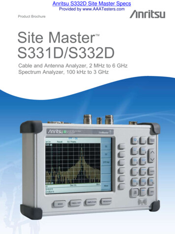
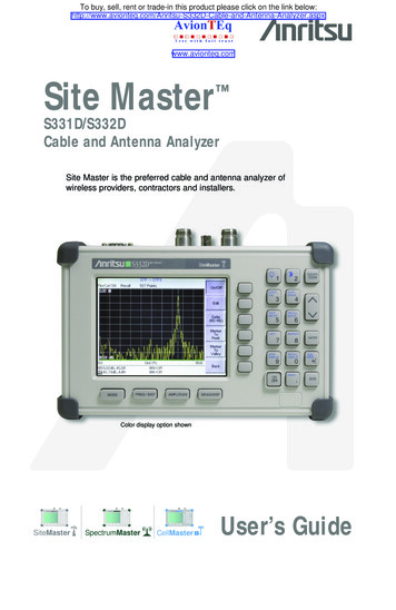
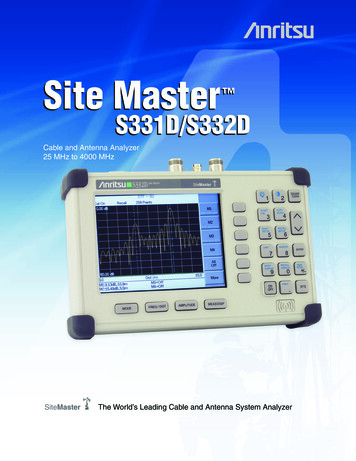
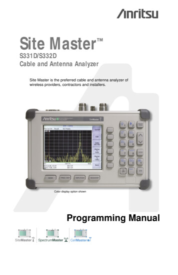
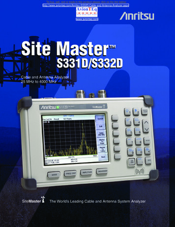
To buy, sell, rent or trade-in this product please click on the link and-Antenna-Analyzer.aspxwww.avionteq.comSite Master S331D/S332DCable and Antenna Analyzer25 MHz to 4000 MHzSiteMasterThe World’s Leading Cable and Antenna System Analyzer
Site Master is the preferred cable and antencontractors, and installers.Cost Savings and Quality ImprovementWireless market competition requires operators to reduce per site maintenance expense.Site Master’s Frequency Domain Reflectometry (FDR) techniques break away from thetraditional fix-after-failure maintenance process by finding small, hard to identifyproblems before major failures occur.Sixty to eighty percent of a typical cell site’s problems are caused by problematic cables,connectors and antennas. When cables or antennas are contaminated with moisture,damaged, or mis-positioned during storms; Site Master identifies the problem quickly.Antenna degradation reduces the cell coverage pattern and can cause dropped calls.Site Master can pinpoint the antenna problem from ground level in a few secondsmaking climbing the antenna tower unnecessary.A poorly installed weather seal will corrode connectors and, if undetected, willeventually damage an expensive coaxial cable. Site Master has the sensitivity to identifythe connector problem before the cable is damaged. Distance-To-Fault provides theclearest indication of troubled areas.Site MasterRevolutionizesCable andAntennaSweeping inthe WirelessIndustry.Rugged and ReliableBecause the Site Master was designed specifically for field environments, it caneasily withstand the day-to-day punishment of field use. The analyzer is almostimpervious to the bumps and bangs typically encountered by portable fieldequipment.Easy-to-UseSite Master operation is straightforward; measurements are obtained through amenu-driven user interface that is easy to use and requires little training. Thelarge and high resolution LCD display makes test interpretation easy and quick.Displays are available in either monochrome or color (Option 3). A full rangeof markers enable the user to make accurate measurements. Limit lines simplifymeasurements allowing users to create quick and simple pass/fail tests.FlexCal ON0.00 dBPR –– RL1Restaurar 259 PointsOpcionesFeatures local language graphical user interface support inEnglish, Chinese, Japanese, French, German, and Spanish.RelojFlexCal ON0.00 dBPR –– RL1Autoverificación 259Estado60.00 dB1550.0Freq (MHz)2150.0LanguageEspañol60.00 dB1550.0(MHz)2150.0Language
nna analyzer of wireless service providers,FDR TechniqueFrequency Domain Reflectometry, (FDR), and Time Domain Reflectometry, (TDR), have similar acronyms, and bothtechniques are used to test transmission lines. But, that’s where the similarities end. TDRs are not sensitive to RFproblems: the TDR stimulus is a DC pulse, not RF. Thus, TDRs are unable to detect system faults that often lead tosystem failures. Additionally, FDR techniques save costly, time-consuming trouble shooting efforts by testing cablefeedline and antenna systems at their proper operating frequency.Deficient connectors, lightning arrestors, cables, jumpers, or antennas are replaced before call quality is compromised.Quick, Simple MeasurementsSite Master performs various RF measurements aimed at simplifying cable feedline and antenna system analysis: ReturnLoss, SWR, Cable Loss and Distance-to-Fault (DTF). A single key selection on the main menu activates the desiredmeasurement mode.RL –– RL1FlexCal ON0.00 dBRecall259 PointsM1M2Return Loss, SWRM3Return Loss and SWR "system" measurements ensure conformance tosystem performance engineering specifications. Measurement easily togglesbetween either one of the two modes and can be performed withoutclimbing the tower.M460.00 39,1982.6MHzAllOffFreq (MHz)M3:22.91,1777.9MHzM4:29.34,1926.7MHzM6 Off2150.0MoreCL –– CL–S21FlexCal ON0.00 dBRecall259 PointsF1F2SignalStandard5.00 dB1550.0F1 1550.0 MHzF2 2150.0 MHzFlexCal ON0.00 dBRecallCable Loss measurements measure the level of insertion loss within thecable feedline system. Insertion loss can be verified prior to deployment,when you have access to both ends of the cable, or on installed cableswithout access to the opposite end.Site Master automatically calculates and displays the average cable loss sothere is no more guess work or a need to perform calculations in the field.Freq (MHz)2150.0Avg Cable Loss 1.80 dBDistance-to-FaultDTF –– DTF1259 PointsM1M2M3M4AllOff60.00 dB0.0M1:34.89dB, 0.3ftM2:41.83dB,17.4ftCable LossDist ance-To-Fault pinpoints the location andreflection amplitude of transmission linecomponents.Although a Return Loss test can tell users the magnitude of signalreflections, it can not tell the precise location of a fault within the feedlinesystem. Distance-To-Fault measurements provide the clearest indication oftrouble areas as it tells us both the magnitude of signal reflection and thelocation of the signal anomaly.Distance-To-Fault measurement capability is built into all Site Master modelsas a standard feature. Return Loss (SWR) measurement data is processedusing Fast Fourier Transform and the resulting data indicates Return Loss(SWR) versus distance.
Spectrum Analysis – Anywhere,Anytime (S332D)The Site Master S332D integrated Spectrum Analysis capability provides the “ultimate” in measurement flexibility forfield environments and applications requiring mobility. With the S332D you can locate, identify, record and solvecommunication systems problems quickly and easily, and with incredible accuracy – making it a perfect solution forconducting field measurements in the 100 kHz to 3 GHz frequency range.One Button MeasurementsThe S332D has dedicated routines for one-button measurements of field strength, channel power, occupied bandwidth,Adjacent Channel Power Ratio (ACPR), Carrier-to-Interference, and interference analysis. These are increasingly criticalmeasurements for today’s wireless communication systems. The simple interface for these complex measurementssignificantly reduces test time and increases analyzer usability.Ref Lvl – 70.0 dBmSA––IA1RBW 3 kHzVBW 1 kHz8 dB/DivAttenDynamicRecallSetIAFreqMeasureIAFreq ToCenterIAFreq AsMarker M1RMS AvgSwp TimeRecallCenter 1.932GHzSpan 3.874MHzCell Standard 1250 kHz CDMAIA Free 1932.48 MHzInterference AnalysisThe S332D can provide assistance in identifying signal types from cellularsites. If you are plagued by an unknown signal, you simply enter thefrequency of the signal of interest as the “IA Frequency” and press“Measure.” The instrument looks at the bandwidth and skirt shape and,if the signal is of a known type, it gives the name of the air interfacestandard (e.g., 1250 kHz CDMA) and the measured bandwidth of the signal.If the signal isn’t a cellular signal, it simply gives the bandwidth.BackAdjacent Channel Power RatioSA––1Ref Lvl 70.0 dBRBW 3 kHzVBW 1 kHz8 dB/DivAttenDynamicRecallACPRRMS ngMeasureCenter 1.932GHzSpan 3.874MHzMain Ch Pwr: –67.15 dBm Main Ch BW: 1.230 000 MHzLower ACPR: –27.30 dBAdj Ch BW: 1.230 000 MHzUpper ACPR: –22.92 dBCh Spacing: 1.230 000 MHzBackA common transmitter measurement is that of adjacent channel leakagepower. This is the ratio of the amount of leakage power in an adjacentchannel to the total transmitted power in the main channel. Thismeasurement is used to replace the traditional two-tone intermodulationdistortion (IMD) test for system non-linear behavior.The result of an ACPR measurement can be expressed either as apower ratio or a power density. In order to calculate the upper andlower adjacent channel values, the S332D allows the adjustment of fourparameters to meet specific measurement needs: main channel centerfrequency, measurement channel bandwidth, adjacent channel bandwidthand channel spacing. When an air interface standard is specified in theS332D, all these values are automatically set to the normal values forthat standard.AM/FM/SSB DemodulatorA built-in demodulator for AM, narrowband FM, wideband FMand single sideband (selectable USB and LSB) allows a technician toeasily identify interfering signals.
RS-232 InterfaceTransfer stored data to andfrom a personal computer (PC)or download to a printer via aserial cable for further analysis.Use PC to automatically controland collect data in the field.Snap-in Fieldreplaceable batterylocationExternal DCPower PortSpectrum Analyzer& Power Meter PortExternal Trigger &External Reference InCable & AntennaAnalyzer PortT1/E1 Receive & Transmit PortS331D Models with Option 50Frequency Converter Module PortOption 6 (S332D) for control ofan external frequency extensionmodule.Save & Recall SetupSave setups for fastrepeatable testing:S332D Models - 20S331D Models - 25Rugged & ReliableChassis DesignRuggedized, lightweight,compact, high-impact housingis designed to withstandrepeated drops and roughhandling. Weather resistantseals and rubber membranekeypad protect unit from dirtand moisture.MarkersSix markers for morecomprehensive measurements.LimitsCreate simple pass/failmeasurements with a singlelimit line, upper and/or lowermask limit lines.Multilingual User InterfaceMulti-language user interfacefeatures on-screen menus andmessages in six differentlanguages: Chinese, English,French, German, Japanese,Spanish.Large HighResolution DisplayStandard VGA (640x480) oroptional color monitor STN(640x480) display featuringcontrast and variable backlighting capability. Easy viewingunder a variety of conditions.Function KeysFour dedicated function keys simplifymeasurement tasks.Soft KeysIntuitive soft key menuand user interface.Save & Recall DisplayUp to 200 memory locations.Alphanumeric data labelingand automatic time/date stampsimplify data management.AM/FM Receiverwith Internal SpeakerBuilt-in AM/FM demodulatorenables testing and troubleshooting of wirelesscommunications systems.An internal speaker andjack are included.Site Master OptionsS331DS332DCable and Antenna Analyzer Spectrum Analyzer AM/FM DemodulatorOption 3 - Color LCD Option 6 - Frequency Converter Interface Option 10 - Bias Tee Option 21 - Transmission Measurement Option 29 - Power Meter Option 50 - T1/E1 Analyzer The FCN4760 is a block down converter for the 4.7 to 6.0 GHzfrequency range. Is is designed to work with an AnritsuSite Master S332D equipped with Option 6.This converter is primarily intended for field use by fixedwireless engineers who are responsible for the design,deployment and optimization of 802.11a networks.It is also used to conduct interference analysis measurements to determine the level of interference andlocate the sources of interference.Frequency Converter Control Module
Handheld Software Tools Powerful PC-based Data Management and AnalysisSoftwareA comprehensive data management and analysis software suite comes with every Site Master unit, providing users with asimple and easy method of managing, archiving, and analyzing system performance, trends, and the general health ofmonitored base stations. Handheld Software Tools also provides a professional report generator, for those times whenrecorded data must be communicated. Handheld Software Tools is Windows 95/98/NT4/2000/ME/XP compatible, and supports long alpha-numericfile names for descriptive data labeling Stores an unlimited number of data traces for comparison of historical performance measurements, easing thetask of trend analysis Transfer data traces between the Site Master and the PC with a single menu selection Has the ability to convert Return Loss measurements to Distance-To-Fault measurements Handheld Software Tools has DTF and Smith Chart analysis capabilitiesColor Display (Option 3)High resolution color STN display for crisp display/trace representation in indoor lighting conditions.Frequency Converter Control Module Interface (Option 6 on S332D only)Connector providing internal control signals to drive the Anritsu Frequency Converter Module.Bias Tee (Option 10 on S332D only)Built-in 18V power supply to bias tower mounted amplifier.Power Meter (Option 29)The power meter performs accurate power measurements, and can display the measured powerin dBm or Watts reducing coverage holes and interference.TM – CRef Lvl 20.0 dBRBW 1 MHzVBW 300 kHz10 ampleAllOffSwp TimeStart 1.600GHzRecallRef Lvl 20.0 dBScale 10 dB/DivCarrier: Y Frame Sync: YAll ErrorsCarrier LossFrame LossBPVCRCStop 2.400GHzAtten DynamicT1 Tester Measure KeysPattern Sync: Y Alarms: None1Bit Errors10:22:14BER 3.31E–08Framing ESFRx Config TerminatePattern QRSSLine Code B8ZSDisplayRaw Data/HistogramInsertErrorsMsr Dur:Manual 10010MeasureDuration10:23:541 Sec UpdatesTime Elapsed: 00:00:05Tx Level 0 dBClock Source InternalError Ins 1 BitsLoop Code CSU In BandAn optional built-in 25 MHz to 3 GHz signal source provides thecapability to measure loss, gain, or isolation of devices such as filters,cables, attenuators, amplifiers, and antennas.BackStart/StopMeasure10K1KTransmission Measurement(Option 21 on S332D only)TimeScaleMoreT1/E1 Analyzer(Option 50 on S331D only)Site Master built-in T1/E1 Analyzer performs T1/E1 functional tests,simplying the task of determining if the source of the problem is onthe wireline or the wireless side. Site Master can display the T1/E1 datain histogram form and collect the data for up to two days. Site Master canalso measure the voltage (Vpp) of the signal and it can also be displayedas dBdsx.
SpecificationsAll specifications apply when the unit is calibrated atambient temperature after a five minute warm up. Typicalvalues are given for reference, and are not guaranteed.Cable and Antenna AnalyzerFrequency Range: 25 MHz to 4.0 GHzFrequency Accuracy: 75 ppm @ 25 CFrequency Resolution: 100 kHzOutput Power: 0 dBm (–10 dBm nominal)Immunity to Interfering Signals:on-
The Site Master S332D integrated Spectrum Analysis capability provides the “ultimate” in measurement flexibility for field environments and applications requiring mobility. With the S332D you can locate, identify, record and solve communication systems problems quickly and easily, and with incredible accuracy – making it a perfect solution for conducting field measurements in the 100 kHz .