Transcription
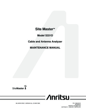
Site MasterTMModel S332DCable, Antenna, and Spectrum AnalyzerMAINTENANCE MANUAL490 JARVIS DRIVE · MORGAN HILL, CA 95037-2809P/N: 10580-00102REVISION PRINTED: JULY 201 COPYRIGHT ã 2004-201 ANRITSU CO.
Table of Contents1. Introduction . . . . . . . . . . . . . . . . . . . . . . . . . . . . . . . . . . . . . . . . . . . 12. Description . . . . . . . . . . . . . . . . . . . . . . . . . . . . . . . . . . . . . . . . . . . . 13. VNA Frequency Accuracy . . . . . . . . . . . . . . . . . . . . . . . . . . . . . . . . . . . . 14. VNA Return Loss Verification . . . . . . . . . . . . . . . . . . . . . . . . . . . . . . . . . . 25. InstaCal Module Verification . . . . . . . . . . . . . . . . . . . . . . . . . . . . . . . . . . 36. Spectrum Analyzer Frequency Accuracy . . . . . . . . . . . . . . . . . . . . . . . . . . . . 47. Spectrum Analyzer Phase Noise Verification. . . . . . . . . . . . . . . . . . . . . . . . . . 58. Spectrum Analyzer Second Harmonic Distortion Test . . . . . . . . . . . . . . . . . . . . . 69. Spectrum Analyzer Residual Spurious Response Test . . . . . . . . . . . . . . . . . . . . . 710. Spectrum Analyzer Resolution Bandwidth Accuracy Test . . . . . . . . . . . . . . . . . . 911. Spectrum Analyzer Measurement Accuracy Verification . . . . . . . . . . . . . . . . . . 1212. Power Monitor Verification (Option 5) . . . . . . . . . . . . . . . . . . . . . . . . . . . . 2113. Bias Tee Verification (Option 10) . . . . . . . . . . . . . . . . . . . . . . . . . . . . . . . 2214. Bias Tee Verification (Option 10A) . . . . . . . . . . . . . . . . . . . . . . . . . . . . . . 2315. Transmission Measurement Verification (Option 21) . . . . . . . . . . . . . . . . . . . . 2416. Power Meter Verification (Option 29) . . . . . . . . . . . . . . . . . . . . . . . . . . . . 2617. FCN4760 Frequency Converter Verification . . . . . . . . . . . . . . . . . . . . . . . . . 2918. Battery Pack Removal and Replacement. . . . . . . . . . . . . . . . . . . . . . . . . . . 3519. Battery Information . . . . . . . . . . . . . . . . . . . . . . . . . . . . . . . . . . . . . . 3720. Front Panel Assembly Removal and Replacement. . . . . . . . . . . . . . . . . . . . . . 3821. LCD Assembly Replacement . . . . . . . . . . . . . . . . . . . . . . . . . . . . . . . . . 4022. Key Pad PCB Replacement . . . . . . . . . . . . . . . . . . . . . . . . . . . . . . . . . . 4023. Key Pad Membrane Replacement . . . . . . . . . . . . . . . . . . . . . . . . . . . . . . 4124. Main PCB Assembly Replacement . . . . . . . . . . . . . . . . . . . . . . . . . . . . . . 4125. Option 5 Power Monitor PCB Assembly Replacement . . . . . . . . . . . . . . . . . . . 4326. Accessories and Replaceable Parts . . . . . . . . . . . . . . . . . . . . . . . . . . . . . . 4427. Customer Service . . . . . . . . . . . . . . . . . . . . . . . . . . . . . . . . . . . . . . . 46Site Master MMi
1. IntroductionThis manual provides maintenance instructions for the Site Master Model S332D Cable, Antenna andSpectrum Analyzer. It describes the product and provides performance verification procedures, parts replacement procedures, and a replaceable parts list.2. DescriptionThe Site Master is a handheld SWR/RL (standing wave ratio/return loss), Distance-To-Fault, spectrumanalysis, and power meter (optional) measurement instrument. It combines a synthesized source, VSWRbridge, receiver, and spectrum analyzer circuitry in a compact instrument.The following sections contain tests that can be used to verify the performance of the Site Master ModelS332D.Throughout this manual, the term “VNA” denotes Return Loss, SWR, Cable Loss and DTF modes, andthe term “SPA” denotes Spectrum Analyzer mode. All other modes are referenced individually.3. VNA Frequency AccuracyThe following test can be used to verify the CW frequency accuracy of the Site Master. Measurement calibration of the Site Master is not required for this test.a. Equipment Required:· Spectrum Analyzer Anritsu Model MS2665C or equivalent· 10 MHz Reference Standardb. Procedure:1. Connect a 10 MHz Reference signal to the 10 MHz STD Ref In of the MS2665C or equivalent.2. Press and hold the ESCAPE/CLEAR key, then press the ON/OFF key to turn on the Site Master.(This sets the instrument to the factory preset state.)NOTE: Before continuing, allow a five minute warm up for the internal circuitry to stabilize.3. Press the FREQ/DIST key, then press the F1 soft key and set F1 to 1000 MHz, then press theENTER key.4. Press the F2 soft key, set F2 to 1000 MHz, then press the ENTER key.5. Press the MEAS/DISP key, then press the Fixed CW soft key to turn Fixed CW On.6. Connect the RF cable from the Site Master Reflection Test Port to the RF Input on the MS2665Cor equivalent.7. Set up the MS2665C as follows:(a) Press the Preset key, then select Preset All (F1).(b) Press the Frequency key.(c) Press the 1 key and then the GHz key to change the Center Frequency to 1 GHz.(d) Press the Span key.(e) Press the 7, 5, 0, and kHz keys sequentially to change the Frequency Span to 750 kHz.(f) Press the RBW key.(g) Press the 1, 0 and kHz keys sequentially to change the RBW to 10 kHz.(h) Press the VBW key.(i) Press the Filter Off soft key (F3) to turn the VB filter off.(j) Press the Amplitude key.Site Master MM1
(k) Press the 0, and dBm keys sequentially to change the Reference Level to 0 dBm.(l) Press the Log Scale soft key (F5)(m) Select 2 dB/Div (F3) and the press the return soft key.NOTE: If the Site Master has gone into the hold mode, press the RUN/HOLD key to return to normalmode.8. When a peak response appears on the Spectrum Analyzer, press the Marker Peak Search key onthe Spectrum Analyzer. Verify that the marker peak readout value is 1000 MHz 75 kHz.9. On the Site Master, press the MEAS/DISP key then the Fixed CW soft key to turn Fixed CW off.4. VNA Return Loss VerificationThe following test can be used to verify the accuracy of return loss measurements. Measurement calibration of the Site Master is required for this test.a. Equipment Required:· 20 dB offset, Anritsu SC7423· 6 dB offset, Anritsu SC7424· Open/Short, Anritsu 22N50· 50 Ohm Termination, Anritsu 28N50-2 or SM/PLb. Procedure:1. Press and hold the ESCAPE/CLEAR key, then press the ON/OFF key to turn on the Site Master.(This sets the instrument to the factory preset state.)NOTE: Before continuing, allow a five minute warm up for the internal circuitry to stabilize.2. Press the MODE key.3. Use the Up/Down arrow key to highlight Return Loss, then press ENTER.4. Press the START CAL key.5. Follow the instructions on the screen to perform a calibration using a 22N50 Open/Short and28N50-2 or SM/PL Termination.6. Connect the 20 dB offset to the Refl Test Port and verify that the reading is 20 dB 1.7 dB.7. Connect the 6 dB offset to the Refl Test Port and verify that the reading is 6 dB 1.2 dB.2Site Master MM
5. InstaCal Module VerificationThis test verifies the performance of the Anritsu Site Master InstaCal Calibration Module. The InstaCalModule, part number ICN50, is an optional accessory for the S332D.a. Equipment Required:· InstaCal Module, part number ICN50· 20 dB offset, Anritsu SC5270· 6 dB offset, Anritsu SC5237b. Procedure1. Press and hold the ESCAPE/CLEAR key, then press the ON/OFF key to turn on the Site Master.(This sets the instrument to the factory preset state.)NOTE: Before continuing, allow a five minute warm up for the internal circuitry to stabilize.2. Press the MODE soft key.3. Use the Up/Down arrow key to highlight RETURN LOSS, then press ENTER.4. Press the START CAL key. The message “CONNECT OPEN or InstaCal TO RF Out PORT” willappear in the display.5. Connect the InstaCal module to the RF Out port and press the ENTER key.NOTES: If this particular InstaCal module has been used to calibrate this Site Master before, the SiteMaster senses the familiar InstaCal module and automatically calibrates the unit using the OSL procedure.If the Site Master senses that the characterization data for the InstaCal module connected to this SiteMaster is different than the one currently stored, it will display soft key options to keep or replace theInstaCal characterization data.Selecting the YES soft key transfers all of the characterization data from this InstaCal module to theSite Master. The transfer may take up to three minutes. This option is preferred if this InstaCal moduleis to stay with this particular Site Master. Once completed, the data will not need to be transferredagain for this combination of Site Master and InstaCal module.Selecting the NO soft key will temporarily transfer only the portion of the characterization data necessary for this particular calibration. This transfer takes approximately 30 to 60 seconds, and will have tobe repeated every time a calibration is done using this combination of Site Master and InstaCal module.6. Verify that the calibration has been properly performed by checking that the CAL ON! message isdisplayed in the upper left corner of the display.7. Remove the InstaCal module from the RF Out port and connect the 20 dB Offset to the RF Outport.8. Measure the return loss of the 20 dB Offset. The level should be 20 dB, 2 dB across the calibrated frequency range.9. Remove the 20 dB Offset from the RF Out port and connect the 6 dB Offset to the RF Out port.10. Measure the return loss of the 6 dB Offset. The level should be 6 dB, 1.2 dB across the calibrated frequency range.Site Master MM3
6. Spectrum Analyzer Frequency AccuracyThe following test can be used to verify the CW frequency accuracy of the Site Master Spectrum Analyzer.a. Equipment Required:· Anritsu MG3692A Synthesized Signal Source, with option 15A or equivalent· Anritsu 34RSN50 50 ohm adapter or equivalent· Anritsu 15NNF50-1.5C RF Coaxial Cable or equivalent· 10 MHz Reference Standard· BNC male to BNC male coaxial cableb. Procedure:1. Connect the 10 MHz reference source to the Anritsu MG3692A Synthesized Signal Source.2. Connect the output of the source to the RF Input of the Site Master.3. Connect the external power supply (Anritsu part number 40-168) to the Site Master.4. Press and hold the ESCAPE/CLEAR key, then press the ON/OFF key to turn on the Site Master.(This sets the instrument to the factory preset state.)5. Turn on the 10 MHz reference source and the Anritsu MG3692A Synthesized Signal Source.6. Set the MG3692A output to 2000 MHz CW, with an RF output level of 0 dBm.NOTE: Before continuing, allow a 30-minute warm up for the internal circuitry to stabilize.7. On the Site Master, press the MODE key. Use the up/down arrow key to highlight Spectrum Analyzerand press ENTER to select spectrum analyzer mode.8. Press the AMPLITUDE key and the Ref Level soft key.9. Enter 20 and press the ENTER key to set the Reference Level to 20 dBm.10. Press the FREQ/DIST key and the Center soft key.11. Enter 2000 and press ENTER to set the center frequency to 2000 MHz.12. Press the Span soft key, enter 20, and press the kHz soft key to set the span to 20 kHz.13. Confirm that the RBW is 100 Hz, and the VBW is 30 Hz. If adjustment of the RBW and VBW arerequired:(a) Press the MEAS/DISP key and the Bandwidth soft key.(b) Press the RBW Manual soft key and use the Up/Down arrow key to select 100 Hz. Press ENTERto set the resolution bandwidth to 100 Hz.(c) Press the VBW Manual soft key and use the Up/Down arrow key to select 30 Hz. Press ENTER toset the video bandwidth to 30 Hz.14. Press the MARKER key, then the M1 soft key.15. Select the Edit soft key and use the Up/Down arrow key to center the marker on the waveform.Verify that the marker frequency is 2000 MHz 4 kHz.4Site Master MM
7. Spectrum Analyzer Phase Noise VerificationThis test can be used to verify the phase noise of the Site Master Spectrum Analyzer.a. Equipment Required:· Anritsu MG3692A Synthesized Signal Source, with options 2A, 4 and 15A, or equivalent· Anritsu 34RSN50 50 ohm adapter or equivalent· Anritsu 15NNF50-1.5C RF Coaxial Cable or equivalentb. Procedure:1. Connect the output of the source to the Site Master RF Input.2. Connect the external power supply (Anritsu part number 40-168) to the Site Master.3. Press and hold the ESCAPE/CLEAR key, then press the ON/OFF key to turn on the Site Master.(This sets the instrument to the factory preset state.)NOTE: Before continuing, allow a 30-minute warm up for the internal circuitry to stabilize.4. Set the MG3692A output to 1000 MHz CW, with an RF output level of –30 dBm.5. On the Site Master, press the MODE key. Use the Up/Down arrow key to highlight Spectrum Analyzer, then, press the ENTER key to select spectrum analyzer mode.6. Press the MEAS/DISP key and the Bandwidth soft key.7. Press the RBW Manual soft key and use the Up/Down arrow key to select 1 kHz. Press ENTER toset the resolution bandwidth to 1 kHz.8. Press the VBW Manual soft key and use the Up/Down arrow key to select 30 Hz. Press ENTER toset the video bandwidth to 30 Hz.9. Press the FREQ/DIST key and the CENTER soft key.10. Enter 1000 and press the ENTER key to set the center frequency to 1000 MHz.11. Press the SPAN soft key and enter 0.1. Press the ENTER key to set the span to 0.100 MHz.12. Press the AMPLITUDE key.13. Press the REF LEVEL soft key and enter –27. Press ENTER to set the reference level to –27 dBm.14. Press the MARKER key, then the M1 soft key.15. Press EDIT and enter 1000. Press ENTER to set the M1 marker frequency to 1000 MHz.16. Press the BACK soft key and the M2 soft key.17. Press EDIT and enter 1000.03. Press ENTER to set the M2 marker frequency to 1000.03 MHz (30kHz higher than the center frequency).18. Press the DELTA (M2–M1) soft key.19. Press the RUN/HOLD key and read and record the D 2 reading20. Press the RUN/HOLD key to read and record five values, then calculate the average of the five recorded values.21. Subtract 30 dB from the average value and verify that the result is –75 dBc/Hz. (For example:–45 dBc measured – 30 dB –75 dBc/Hz.)NOTE: The measured value is converted to dBc/Hz using
This manual provides maintenance instructions for the Site Master Model S332D Cable, Antenna and Spectrum Analyzer. It describes the product and provides performance verification procedures, parts re-placement procedures, and a replaceable parts list. 2. Description The Site Master is a handheld SWR/RL (standing wave ratio/return loss), Distance-To-Fault, spectrum analysis, and power meter .