Transcription
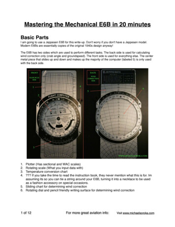
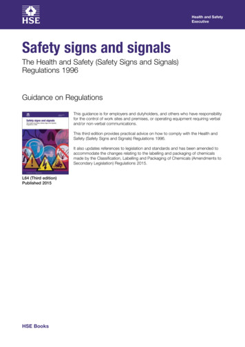
INTRODUCTION27 FEB 04161ICAO RECOMMENDED AIRPORT SIGNS, RUNWAY AND TAXIWAY MARKINGSMANDATORY INSTRUCTION SIGNSApplicationA mandatory instruction sign identifies a location beyond which an aircraft taxiing shall not proceed unlessauthorized by ATC. At uncontrolled airports, use appropriate precautions prior to proceeding. Mandatoryinstruction signs may include runway designation signs, category I, II or III holding position signs, runwayholding postion signs and NO ENTRY signs. Runway-holding position markings are supplemented at ataxiway/runway or a runway/runway intersection with a runway designation sign. A runway designation sign ata taxiway/runway intersection or a runway/runway intersection will be supplemented with a location sign in theoutboard (farthest from the taxiway) position, as appropriate. A NO ENTRY sign is provided when entry into anarea is prohibited.LocationA runway designation sign at a taxiway/runway intersection or a runway/runway intersection will be located oneach side of the runway-holding position marking facing into the direction of approach to the runway. Acategory I, II or III holding position sign will be located on each side of the runway-holding position markingfacing into the direction of the approach to the critical area. A runway-holding position sign will be located oneach side of the runway-holding position facing the approach to the obstacle limitation surface or ILS/MLScritical/sensitive area, as appropriate.CharacteristicsMandatory instruction signs have a red background, with white inscriptions. The inscriptions on a runwaydesignation sign will consist of the runway designations of the intersecting runway properly oriented to theviewing direction. The inscriptions on a category I, II or III or joint II/III holding position sign will consist of therunway designator followed by CAT I, CAT II or CAT III as appropriate. The inscriptions on a runway-holdingposition sign will consist of the taxiway designation and a number.LEFT SIDELOCATION/RUNWAY DESIGNATIONRUNWAY-HOLDING POSITIONLOCATION/RUNWAY DESIGNATIONRIGHT SIDERUNWAY DESIGNATION/LOCATIONRUNWAY DESIGNATION/CATEGORY II HOLDING POSTIONNO ENTRYRUNWAY DESIGNATION/LOCATION JEPPESEN SANDERSON, INC., 2004. ALL RIGHTS RESERVED.
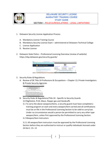
162INTRODUCTION27 FEB 04ICAO RECOMMENDED AIRPORT SIGNS, RUNWAY AND TAXIWAY MARKINGSINFORMATION SIGNSApplicationAn information sign identifies a specific location or routing. Information signs include: direction, location,destination, runway exit and runway vacated signs. A runway exit sign is provided to identify a runway exit. Arunway vacated sign is provided where the exit taxiway has no centerline lights and there is a need to indicateleaving the runway, the ILS/MLS critical/sensitive area. A destination sign indicates the direction to a specificdestination, such as cargo, general aviation, etc. A combined location and direction sign indicates routinginformation prior to a taxiway intersection. A direction sign identifies the designation and direction at a taxiwayintersection. A location sign is provided in conjunction with a runway designation sign except at arunway/runway intersection.LocationInformation signs are located on the left-hand side of the taxiway in line with the taxiway intersection marking.Where there is no taxiway intersection marking the sign is installed at least 40m away from the centerline of theintersecting taxiway. A runway exit sign is located on the same side of the runway as the exit is located (i.e. leftor right). A runway vacated sign is located at least on one side of the taxiway.CharacteristicsAn information sign other than a location sign consists of an inscription in black on a yellow background. Alocation sign consists of an inscription in yellow on a black background. A runway exit sign consists of the exittaxiway designator and an arrow indicating the direction to follow. A runway vacated sign depicts the runwayholding position marking as shown in the example in Pattern A in the example under "Runway-Holding PositionMarkings". The inscriptions on a destination sign comprise an alpha, alphanumerical or numerical messageidentifying the destination plus an arrow indicating the direction to proceed. The inscriptions on a direction signcomprise an alpha, alphanumerical message identifying the taxiway(s) plus an arrow or arrows appropriatelyoriented as shown in the example. The inscriptions on a location sign comprise the destination of the locationtaxiway, runway or other pavement the aircraft is on or is entering.Note: Generally, signs should be lighted if the runway or taxiway on which they are installed is lighted.LEFT SIDERIGHT DESTINATIONRUNWAY VACATED/LOCATIONLOCATION/RUNWAY VACATEDRUNWAY EXITLOCATIONRUNWAY /DIRECTIONINTERSECTION TAKE-OFF JEPPESEN SANDERSON, INC., 2004. ALL RIGHTS RESERVED.
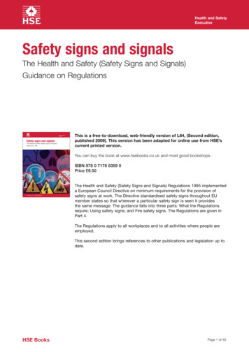
INTRODUCTION27 FEB 04163ICAO RECOMMENDED AIRPORT SIGNS, RUNWAY AND TAXIWAY MARKINGSMANDATORY INSTRUCTION MARKINGSApplicationWhere it is impracticable to install a mandatory instruction sign a mandatory instruction marking is provided onthe surface of the pavement. Where operationally required, such as on taxiways exceeding 60m in width, amandatory instruction sign may be supplemented by a mandatory instruction marking.LocationThe mandatory instruction marking is located on the left-hand side of the taxiway center line marking on theholding side of the runway-holding position marking.CharacteristicsMandatory instruction markings consist of an inscription in white on a red background. Except for a NO ENTRYmarking, the inscription provides information identical to that of the associated mandatory instruction sign. ANO ENTRY marking consists of an inscription in white reading NO ENTRY on a red background.To runway '09'1 m mnm1 m mnm JEPPESEN SANDERSON, INC., 2004. ALL RIGHTS RESERVED.
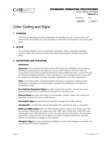
16427 FEB 04INTRODUCTIONICAO RECOMMENDED AIRPORT SIGNS, RUNWAY AND TAXIWAY MARKINGSRUNWAY-HOLDING POSITION MARKINGSApplication and LocationRunway-holding position markings are located at runway holding positions.CharacteristicsAt an intersection of a taxiway and a non-precision, non-instrument or take-off runway or where a singlerunway-holding position is provided at an intersection of a taxiway and a precision approach category I, II, or IIIrunway, the runway-holding position marking will be as shown as in pattern A. Where two or three runwayholding positions are provided at such an intersection, the runway-holding position marking closer to therunway will be as shown as in pattern A, and the markings farther from the runway as in pattern B. Where apattern B runway-holding position marking exceeds 60m in length, the term CAT II or CAT III as appropriate willbe marked on the surface at the ends of the runway-holding position marking. The runway-holding positionmarking displayed at a runway/runway intersection will be perpendicular to the centerline of the runway formingpart of the standard taxiroute. The runway-holding position marking will be shown as in pattern B.Pattern BPattern AINTERMEDIATE HOLDING POSITION MARKINGSApplication and LocationAn intermediate holding position marking is displayed at an intersection of two paved taxiways. It is positionedacross the taxiway coincident with a stop bar or intermediate holding position lights, where provided.CharacteristicsAn intermediate holding position marking consists of a single broken yellow line. JEPPESEN SANDERSON, INC., 2004. ALL RIGHTS RESERVED.
30 DEC 05INTRODUCTION165ICAO RECOMMENDED AIRPORT SIGNS, RUNWAY AND TAXIWAY MARKINGSSTOP BARSAPPLICATIONA stop bar is provided at every runway-holding position when it is intended that the runway will be usedin RVR conditions less than 350m or between 350mand 550m. A stop bar will be provided at an intermediate holding position to supplement markings withlights or where normal stop bar lights might be obscured.LOCATIONStop bars are located across the taxiway at the pointwhere it is desired that traffic stop. Additional lightsmay be provided at the taxiway edge.&RQILJXUDWLRQ CHARACTERISTICSStop bars consist of lights spaced at intervals acrossthe taxiway, showing red in the intended direction ofapproach to the intersection or runway-holding position. Stop bars installed at a runway-holding positionwill be unidirectional, showing red in the direction ofapproach to the runway.RUNWAY GUARD LIGHTS&RQILJXUDWLRQ %APPLICATIONRunway guard lights, configuration A, are located ateach taxiway/runway intersection associated with arunway intended for use in:RVR conditions less than 550m where a stop bar isnot installed; andRUNWAY MARKINGSRVR conditions between 550m and 1200m wheretraffic density is medium or low.Runway markings are white.Configuration A or B or both will be provided at eachtaxiway/runway intersection where the configurationof the intersection needs to be enhanced, such ason a wide throat taxiway.LOCATIONRunway guard lights, configuration A, are located ateach side of a taxiway, whereas in configuration Bthey are located across the taxiway.CHARACTERISTICSRunway guard lights are unidirectional flashing yellow lights. JEPPESEN SANDERSON, INC. 2004, 2005. ALL RIGHTS RESERVED.
166INTRODUCTION30 DEC 05ICAO RECOMMENDED AIRPORT SIGNS, RUNWAY AND TAXIWAY MARKINGSTHRESHOLD MARKINGSRUNWAY CENTERLINE MARKINGSAPPLICATION AND LOCATIONAPPLICATION AND LOCATIONThreshold markings are provided at the threshold ofa paved instrument and non-instrument runway intended for use by international commercial air transport.A runway centerline marking is provided on a pavedrunway along the centerline.CHARACTERISTICSRunway centerline markings consist of a line of uniformly spaced stripes and gaps. Stripes are normally 30m long, gaps 20m long.Runway threshold markings consist of a pattern oflongitudinal stripes of uniform dimensions disposedsymmetrically about the centerline of a runway. Thenumber of stripes shall be in accordance with therunway width as follows:CHARACTERISTICSHIGH SPEED TAXIWAY TURN-OFFINDICATOR LIGHTS (HSTIL)ICAO term is Rapid Exit Taxiway Indicator Lights(RETIL)RUNWAY WIDTHNUMBER OFSTRIPES18m4APPLICATION23m630m8HSTIL should be provided on a runway intended foruse in RVR conditions less than 350m and/or wheretraffic density is heavy.45m12LOCATION60m16A set of HSTIL shall be located on the runway on thesame side of the runway centerline as the associated high speed turn-off taxiway, in the configurationshown below.Where a runway designator is placed within athreshold marking, there will be a minimum of threestripes on each side of the runway centerline.Stripes are at least 30m long.RUNWAY DESIGNATION MARKINGSAPPLICATION AND LOCATIONCHARACTERISTICSHSTIL are fixed unidirectional yellow lights, alignedso as to be visible to the pilot of a landing airplane inthe direction of approach to the runway.Runway designation markings are located at thethresholds of a paved runway.CHARACTERISTICSRunway designation markings consists of a two-digitnumber located at the threshold. On parallel runways each runway designation number is supplemented by a letter in the order from left to right whenviewed from the direction of approach.3RLQW RIWDQJHQF\ P P P P5(7,/V P ODWHUDOVSDFLQJ P P P5XQZD\ FHQWHUOLQH JEPPESEN SANDERSON, INC. 2005. ALL RIGHTS RESERVED.
INTRODUCTION27 FEB 04167ICAO RECOMMENDED AIRPORT SIGNS, RUNWAY AND TAXIWAY MARKINGSRUNWAY TOUCHDOWN ZONE MARKINGSApplicationA touchdown zone marking is provided in the touchdown zone of a paved precision approach runway and andnon-precision approach runway or non-instrument runway where additional identification of the touchdownzone is required.Location and CharacteristicsA touchdown zone marking shall consist of pairs of rectangular markings symmetrically disposed about therunway centerline with the number of pairs related to the landing distance available (LDA).A touchdown zone marking shall conform to either of the two runway patterns shown below.LDA or DISTANCE BETWEEN THRESHOLDSLess than 900mLess than 1200m but not less than 900mLess than 1500m but not less than 1200mLess than 2400m but not less than 1500m2400m or morePAIR(S) of MARKINGS12346RUNWAY AIMING POINT MARKINGSApplicationAn aiming point marking will be provided at each approach end of a paved instrument or non-instrumentrunway.Location and CharacteristicsAn aiming point marking consists of two conspicuous stripes in conformity with the dimensions shown for therunway patterns in the example shown under "Runway Touchdown Zone and Aiming Point Markings". JEPPESEN SANDERSON, INC., 2004. ALL RIGHTS RESERVED.
16827 FEB 04INTRODUCTIONICAO RECOMMENDED AIRPORT SIGNS, RUNWAY AND TAXIWAY MARKINGSRUNWAY TOUCHDOWN ZONE AND AIMING POINT MARKINGS(continued) JEPPESEN SANDERSON, INC., 2004. ALL RIGHTS RESERVED.
INTRODUCTION27 FEB 04169ICAO RECOMMENDED AIRPORT SIGNS, RUNWAY AND TAXIWAY MARKINGSRUNWAY SIDE STRIPE MARKINGApplicationRunway side stripe markings are provided between the thresholds of a paved runway where there is lack ofcontrast between the runway edges and the shoulders. Runway side stripe markings are provided on precisionapproach runways.Location and CharacteristicsRunway side stripe markings consist of two stripes, one placed along each edge of the runway no more than30m from the runway centerline regardless of the runway width.DISPLACED THRESHOLD MARKINGSCLOSED RUNWAYS, TAXIWAYS OR PARTS THEREOFApplication and LocationA closed marking will be displayed at each end of a runway or portion thereof, declared permanently closed touse by all aircraft. Additionally, markings are placed so that the maximum interval between the markings doesnot exceed 300m. On a taxiway, a closed marking shall be placed at least at each end of a taxiway or portionthereof that is closed.CharacteristicsThe closed marking is shaped like a cross. The marking is white when displayed on a runway and yellow whendisplayed on a taxiway.NON LOAD-BEARING SURFACESThe boundary between load-bearing surfaces and non load-bearing surfaces, such as shoulders for taxiways,holding bays, aprons and other non load-bearing surfaces which, if used, might result in damage to the aircraftare indicated by a taxi side stripe. This marking consists of a pair of solid lines the same color as the taxiwaycenterline marking. JEPPESEN SANDERSON, INC., 2004. ALL RIGHTS RESERVED.
17027 FEB 04INTRODUCTIONICAO RECOMMENDED AIRPORT SIGNS, RUNWAY AND TAXIWAY MARKINGSPRE-THRESHOLD AREA MARKING (CHEVRON MARKING)When the paved surface prior to the threshold exceeds 60m in length and is not suitable for use by aircraft, theentire length will be marked with a chevron marking (preferably yellow) pointing in the direction of the runwaythreshold.THRESHOLDPRE-THRESHOLD AREARUNWAYCENTERLINEEND OF ICAO RECOMMENDED AIRPORT SIGNS, RUNWAY AND TAXIWAY MARKINGS JEPPESEN SANDERSON, INC., 2004. ALL RIGHTS RESERVED.
INTRODUCTION21 NOV 97151UNITED STATES AIRPORT SIGN SYSTEMSMANDATORY SIGNSMandatory signs have a red background with a white inscription. They are used to denote an entrance to a runwayor critical area and areas where an aircraft is prohibited from entering.TAXIWAY/RUNWAY ANDRUNWAY/RUNWAY HOLDINGILS CRITICAL AREA HOLDINGThis sign is located at the holding position ontaxiways that intersect a runway or on runways thatintersect other runways. The inscription on the signcontains the designation of the intersecting runway.The runway numbers on the sign are arranged tocorrespond to the respectiverunway threshold. For example,"15-33" indicates that the thresholdfor Runway 15 is to the left and thethreshold for Runway 33 is to theright. A runway holding position sign on a taxiway willbe installed adjacent to holding position markings onthe taxiway pavement. On runways, holding positionmarkings will be located only on the runwaypavement adjacent to the sign, if the runway isnormally used by air traffic control for "Land, HoldShort" operations or as a taxiway.On taxiways that intersect the beginning ofthe takeoff runway, only the designation ofthe takeoff runway may appear on the sign,while all other signs will have the designation of both runway directions.At some airports, when the instrument landing systemis being used, it is necessary to hold an aircraft on ataxiway at a location other than thenormal holding position. In thesesituations the holding position sign forthese operations will have the inscription "ILS" and be located adjacent tothe holding position marking on the taxiway.RUNWAY APPROACH AREA HOLDINGAt some airports, it is necessary to hold an aircraft ona taxiway located in the approach or departure areafor a runway so that the aircraft does not interferewith operations on thatrunway. In these situations, a sign with the designation of the approachend of the runway followed by a "dash" (-) and letters"APCH" will be located at the holding position on thetaxiway. In this example, the sign may protect theapproach to Runway 15 and/or the departure forRunway 33.NO ENTRYWhen a sign is located on a taxiway that intersectsthe intersection of two runways, the designations forboth runways will be shown on the sign along witharrows showing the approximate alignment of eachrunway. In addition to showing the approximaterunway alignment, the arrow indicates the direction tothe threshold of the runway whose designation isimmediately next to the arrow.Prohibits an aircraft from entering an area.Typically, this sign would be located on ataxiway intended to be used in only onedirection or at the intersection of vehicleroadways with runways, taxiways oraprons where the roadway may be mistaken as ataxiway or other aircraft movement surface.LOCATION SIGNSLocation signs are used to identify either a taxiway or runway on which the aircraft is located. Other location signsprovide a visual cue to pilots to assist them in determining when they have exited an area. The various locationsigns are described below.Taxiway Location Signs have a black background with a yellow inscription and yellow border. Theinscription is the designation of the taxiway on which the aircraft is located. These signs are installedalong taxiways either by themselves or in conjunction with direction signs or runway holding positionsigns.Runway Location Signs have a black background with a yellow inscription and yellow border. Theinscription is the designation of the runway on which the aircraft is located. These signs are intended tocomplement the information available to pilots through their magnetic compass and typically are installedwhere the proximity of two or more runways to one another could cause pilots to be confused as to whichrunway they are on.Runway Boundary Signs have a yellow background with a black inscription with a graphicdepicting the pavement holding position marking. This sign, which faces the runway and isvisible to the pilot exiting the runway, is located adjacent to the holding position marking on thepavement. The sign is intended to provide pilots with another visual cue which they can use as aguide in deciding when they are "clear of the runway." JEPPESEN SANDERSON, INC., 1992, 1997. ALL RIGHTS RESERVED.
152INTRODUCTION21 NOV 97UNITED STATES AIRPORT SIGN SYSTEMSLOCATION SIGNS (continued)ILS Critical Area Boundary Signs have a yellow background with a black inscription anda graphic depicting the ILS pavement holding position marking. This sign is locatedadjacent to the ILS holding position marking on the pavement and can be seen by pilotsleaving the critical area. The sign is intended to provide pilots with another visual cuewhich they can use as a guide in deciding when they are "clear of the ILS critical area."DIRECTION SIGNSDirection signs have a yellow background with a black inscription. The inscription identifies the designations(s)of the intersecting taxiway(s) leading out of the intersection that a pilot would normally be expected to turn ontoor hold short of. Each designation is accompanied by an arrow indicating the direction of the turn.When more than one taxiway designation is shown on the sign each designation and its associated arrow isseparated from the other taxiway designations by either a vertical message divider or a taxiway location sign.Direction signs are normally located on the left prior to the intersection. When used on a runway to indicate anexit, the sign is located on the same side of the runway as the exit.When the intersection is comprised of only one crossingtaxiway, it will have two arrowsassociated with the crossingtaxiway.Taxiway Direction Sign orRunway Exit SignDESTINATION SIGNSDestination signs also have a yellow background with a black inscription indicating a destination on the airport.These signs always have an arrow showing the direction of the taxi route to that destination. When the arrow onthe destination sign indicates a turn, the sign is located prior to the intersection.Destinations commonly shown on these types of signs include runways, aprons, terminals, military areas, civilaviation areas, cargo areas, international areas, and fixed base operators. An abbreviation may be used as theinscription on the sign for some of these destinations.Outbound Destination Sign toDifferent Runways. More thanone runway, separated by adot, is shown where the taxiingroute is common to both runways.Outbound Destination SignInbound Destination SignINFORMATION SIGNSInformation signs have a yellow background with a black inscription. They are used to provide the pilot withinformation on such things as areas that cannot be seen from the control tower, applicable radio frequencies,and noise abatement procedures. The airport operator determines the need, size, and location for these signs.RUNWAY DISTANCE REMAINING SIGNSRunway Distance Remaining Signs are used to provide distance remaining information to pilotsduring take-off and landing operations. The signs are located along one or both sides of the runway,and the inscription consists of a white numeral on a black background. The signs indicate thedistance remaining in thousands of feet.The distance remaining may be 50 ft less than shown on the sign. There is a 50 ft tolerance in the signplacement. Some signs may be omitted because they cannot meet this tolerance.When runway length is not an even multiple of 1000 ft, half the "additional distance" is added to the first and lastsign placement. The example below is for a 6900 ft runway. JEPPESEN SANDERSON, INC., 1992, 1997. ALL RIGHTS RESERVED.
30 DEC 05INTRODUCTION157UNITED STATES INSTRUMENT RUNWAY MARKINGSUNITED STATES INSTRUMENT RUNWAY MARKINGSDISPLACED THRESHOLD MARKINGS AND MARKINGS FOR BLAST PADS AND STOPWAYS JEPPESEN SANDERSON, INC. 1992, 2005. ALL RIGHTS RESERVED.
158INTRODUCTION30 DEC 05UNITED STATES INSTRUMENT RUNWAY MARKINGSCHARACTERISTICSENHANCED TAXIWAY CENTERLINEAND RUNWAY HOLDING POSITIONMARKINGSAPPLICATIONa. Taxiway centerline markings are modified beginning 150 feet prior to the runway holding positionmarkings (where sufficient space is available)with the addition of parallel dashed yellow lineson both sides of the existing taxiway centerline.The taxiway centerline markings prior to runwayholding positions are being enhanced to provide pilots with a visual cue that they are approaching aholding position. Runway holding position markingsare also being extended onto the paved shoulders oftaxiways and may be accompanied by surface painted holding position signs. These new markings willbe the standard for many major airports in the United States.b. Existing holding position markings are extendedonto paved taxiway shoulders allowing them tobe visible to pilots from the side windows of thecockpit for many aircraft.c. Runway holding position signs may be paintedon the surface of the taxiway on both sides of thetaxiway centerline leading up to the runway holding position marking (where sufficient space isavailable), white numbers on red background.(1' 2) 81,7(' 67 7(6 ,53257 6,*16 1' ,167580(17 581: 0 5.,1*6 JEPPESEN SANDERSON, INC. 2005. ALL RIGHTS RESERVED.
ICAORECOMMENDED AIRPORT SIGNS, RUNWAY AND TAXIWAY MARKINGS MANDATORY INSTRUCTIONMARKINGS Application Whereit is impracticable to install a mandatory instruction sign a mandatory instruction markingis provided on the surface of the pavement. Where operationall