Transcription
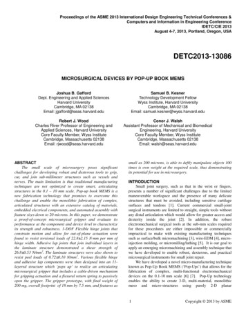
Proceedings of the ASME 2013 International Design Engineering Technical Conferences &Computers and Information in Engineering ConferenceIDETC/CIE 2013August 4-7, 2013, Portland, Oregon, USADETC2013-13086MICROSURGICAL DEVICES BY POP-UP BOOK MEMSJoshua B. GaffordDept. Engineering and Applied SciencesHarvard UniversityCambridge, MA 02138Email: jgafford@seas.harvard.eduSamuel B. KesnerTechnology Development FellowWyss Institute, Harvard UniversityCambridge, MA 02138Email: samuel.kesner@wyss.harvard.eduRobert J. WoodCharles River Professor of Engineering andApplied Sciences, Harvard UniversityCore Faculty Member, Wyss InstituteCambridge, Massachusetts 02138Email: rjwood@seas.harvard.eduConor J. WalshAssistant Professor of Mechanical and BiomedicalEngineering, Harvard UniversityCore Faculty Member, Wyss InstituteCambridge, Massachusetts 02138Email: walsh@seas.harvard.eduABSTRACTThe small scale of microsurgery poses significantchallenges for developing robust and dexterous tools to grip,cut, and join sub-millimeter structures such as vessels andnerves. The main limitation is that traditional manufacturingtechniques are not optimized to create smart, articulatingstructures in the 0.1 – 10 mm scale. Pop-up book MEMS is anew fabrication technology that promises to overcome thischallenge and enable the monolithic fabrication of complex,articulated structures with an extensive catalog of materials,embedded electrical components, and automated assembly withfeature sizes down to 20 microns. In this paper, we demonstratea proof-of-concept microsurgical gripper and evaluate itsperformance at the component and device level to characterizeits strength and robustness. 1-DOF Flexible hinge joints thatconstrain motion and allow for out-of-plane actuation werefound to resist torsional loads of 22.8 2.15 N·mm per mm ofhinge width. Adhesive lap joints that join individual layers inthe laminate structure demonstrated a shear strength of26.8 0.53 N/mm2. The laminate structures were also shown toresist peel loads of 0.72 0.10 N/mm2. Various flexible hingeand adhesive lap components were then designed into an 11layered structure which ‘pops up’ to realize an articulatingmicrosurgical gripper that includes a cable-driven mechanismfor gripping actuation and a flexural return spring to passivelyopen the gripper. The gripper prototype, with final weight of200 mg, overall footprint of 18 mm by 7.5 mm, and features assmall as 200 microns, is able to deftly manipulate objects 100times is own weight at the required scale, thus demonstratingits potential for use in microsurgery.INTRODUCTIONSmall joint surgery, such as that in the wrist or fingers,presents a number of significant challenges due to the limitedmaneuverable workspace and the presence of many delicatestructures that must be avoided, including sensitive cartilagesurfaces and tendons [1]. Current commercial small-jointsurgical instruments are limited to straight, simple tools withoutany distal articulation which would allow for greater access anddexterity inside the joint [2]. In addition, the robustelectromechanical surgical tools at the sub-mm scales requiredfor these procedures are either impossible or commerciallyimpractical to make with existing manufacturing techniquessuch as surface/bulk micromachining [3], wire-EDM [4], microinjection molding, or micromilling/lathing [5]. It is our goal toapply an emerging micromachining and assembly technique thatwe have developed to enable robust, dexterous, and practicalmicrosurgical instruments for small joint repair.We have developed a novel micro-manufacturing techniqueknown as Pop-Up Book MEMS (‘Pop-Ups’) that allows for thefabrication of complex, multi-functional electromechanicaldevices on the 0.1-10 mm scale [6] [7]. Pop-Up technologyenables the ability to create 3-D, multi-material, monolithicmeso and micro-structures using purely 2-D planar1Copyright 2013 by ASME
Figure 1: (left) Layup detail of a hinge created with the Pop-Up Book MEMS fabrication technology [1], (right) Device fabricated using PopUp Book MEMS, on a US penny for scalemanufacturing and origami folding techniques. The methoddraws upon techniques from printed circuit (PC) boardmanufacturing, allowing for the straightforward integration ofembedded on-board electronics and power. An example PopUp mechanism, featuring a castellated hinge which allows thetop structural layer to fold in on itself to approximate pin jointmotion, is shown in Figure 1 (left).Pop-Up Book MEMS technology is well-suited for smallmedical and microsurgical applications, as the techniqueenables the manufacture of highly capable and articulatedmechanisms at sub-mm scales. An early example of a selfassembling device manufactured via PopUp MEMS is shown inFigure 1 (right). The nature of PopUp devices will enablemechanisms and implants that can be inserted through smallincisions and ‘pop-up’ to assume their functional form.Embedded sensing and actuation can be directly integrated intothe end-effector to allow for distal actuation and feedbacksensing in teleoperative and cooperative robotic scenarios.While great innovations have been created with Pop-Upfabrication, such as flying microrobots or self-assemblingstructures [7], no work to date has been done to mechanicallycharacterize the strength and robustness of Pop-Up devices. Asour objective is to build devices that will mechanically interactwith the human anatomy, it is crucial to understand the forcesthat these devices can withstand to ensure functional longevityin a mechanically interactive environment. In the followingpaper, we begin with an overview of the Pop-Up Book MEMSmanufacturing process. We provide a discussion of therobustness evaluation experimental methods and presentsignificant results of the evaluation. Finally, we present thedesign, fabrication, and evaluation of an actuated gripperprototype developed using Pop-Up MEMS.POPUP FABRICATION PROCESSMechanisms created with the Pop-Up technology aretypically composed of a number of layups consisting of fivesub-layers: a flexible (polyimide) layer sandwiched betweentwo structural layers, with adhesive in between each layer (seeFigure 1). The number of layers scales roughly with devicecomplexity. In this work, 304 Stainless Steel is used as thestructural material, and Kapton (developed by DuPont) isused as the flexible polyimide. Dupont FR1500 acrylic adhesiveis used to join the layers.An overview of the fabrication process is illustrated Figure2. Beginning with a 2D CAD model of the device, interior andalignment features on each individual layer comprising thelayup are machined via laser ablation using a diode-pumpedsolid-state (DPSS) laser. Each layer is then deburred ifnecessary and exposed to a two-step cleaning process: (1)Isopropyl Alcohol soak and ultrasonic clean (80º C for 10minutes) to remove surface-level particulates, and (2) plasmaetch with argon gas (0.40 mbar at 2-4 sccm for 60s [8]) toremove contaminates and improve the surface microtexture.The layers are then prepped for lamination and each structurallayer is ‘back-tacked’ to deposit the adhesive islands on eachrespective layer such that the adhesive protective backing canbe removed and disposed of. The entire laminate is cured via atwo-hour curing process where heat and pressure (60 psi, 200ºC) are applied to set the adhesive. Following this step, the layupis released from the surrounding alignment scaffold using theDPSS laser and mechanically ‘popped up’ to assume thefunctional form of the prototype. From start to finish, the entirefabrication process takes approximately 10 hours.Figure 2: Pop-Up manufacturing process illustration2Copyright 2013 by ASME
COMPONENT DESIGN AND EVALUATIONFurther development of PopUp technology with specificapplication to medical devices and microsurgical equipmentrequires a thorough understanding of the forces that PopUpstructures can withstand. The technology was originallydeveloped for flying microrobots, so strength-to-weight ratiooptimization was key. As such, limited work has since beendone to characterize the strength and robustness of thesestructures as this had not previously been a primary designconsideration. As we are developing mechanisms that willmanipulate and interact directly with soft-tissue, we performeda robustness analysis to mechanically characterize thetechnology and improve our understanding of the strengthcapabilities of Pop-Up structures at sub-millimeter scales. Thiswork will guide future manufacturing process optimization anddesign projects.EXPERIMENTAL METHODTo evaluate the robustness of the Pop-Up fabricationprocess, a subset of frequently used components had theirstrength properties measured and failure modes examined.These failure modes are: (1) lap shear failure resulting inadhesive delamination (layups both with and without theflexible Kapton layer), (2) delamination via peel failure, and (3)castellated hinge failure via torsional loading. A customaluminum jig with an elastic hinge, capable of friction clampingcomponents 500 µm thick, was fabricated so that the smallspecimens could be evaluated using a standard material tensiletesting machine (Instron Model 5566 with 1 kN static load cell).Illustrations of each strength test, as well as images of testspecimens undergoing testing, are shown Figure 3. Lap shearsamples featured an overlapping area of adhesion to resist shearforces, as per the ASTM protocol set forth in [9]. Lap peelsamples were of similar design, except with perpendicular tabsto obtain a pure peeling motion. Hinge samples featured acastellated hinge with a 10mm lever arm to provide a bendingmoment about the hinge.For each failure mode, a meaningful parameter was variedto obtain trend data for use as scaling guidelines in futuremechanism design. For lap shear and peel failure modes, laparea of adhesion was varied (1mm2, 3mm2, and 5mm2 for lapshear; 3mm2, 9mm2, and 15mm2 for peel). For castellated hingetorsion, hinge width was varied (1mm, 3mm, and 5mm).Five specimens were tested for each varied parameter toobtain a statistically meaningful dataset with which to computeconfidence intervals. Given 3 variables for 4 tests, a total of 60tests were performed to characterize the robustness of thetechnology.ROBUSTNESS RESULTSRaw instron data from each experiment were recorded. Inaddition, a representative sample from each test was furtheranalyzed under a scanning electron microscope (SEM) toexamine any significant qualitative observations regarding thefailure mode. An example raw force/extension curve generatedFigure 3: PopUp strength test specimens (clockwise from top left)Steel-Kapton-Steel Lap Shear, Steel-Steel Lap Shear, CastellatedHinge Torsion, Steel-Kapton-Steel Lap PeelFigure 4: Test data for castellated hinge torsion, demonstratingeffects of stress concentrations inducing failure. Inset showsmicroscopic image of castellated hinge pre-testFigure 5: SEM image of Kapton failure at castellation3Copyright 2013 by ASME
Table 1: Robustness results summary. values denote 95%confidence intervalsFigure 6: Example results of Steel-Kapton-Steel lap shear failure,demonstrating effects of increasing lap areafrom the castellated hinge torsion failure evaluation is shown inFigure 4. The inlaid image is an optical microscopic image ofthe castellated region pre-testing. In addition, an SEM close-upof the failure region for this sample is shown in Figure 5.Aggregate loading curves for Steel-Kapton-Steel lap shearevaluation for the three different lap areas (15 samples) areshown in Figure 6. Loading curves were relatively consistentand devoid of statistical outliers, and scale approximatelylinearly with lap area, as was hypothesized. Similar trends wereobserved with Steel-Steel lap shear, Steel-Kapton-Steel lap peeland castellated hinge torsion evaluations.Raw data were post-processed in MATLAB (Mathworks,Natick, MA, USA) and a statistical analysis was performed.Failure modes of interest were plotted against the variedparameter for that particular test, and linear regression wasperformed to obtain strength data as a function of the featuresize. Standard measurement errors in slope were computedusing a least-squares approach with 95% confidence assuming astudent-t distribution of data [10].Linear fits for each dataset are given in Figure 7 (a), (b),and (c). The results are tabulated in Table 1. Data analysisindicates that trends are sufficiently linear; peel strength datahas the largest 95% confidence interval, comprising roughly13% the magnitude of the fitted linear function. The remainingtests had confidence intervals to within 10%, demonstratingsufficient statistical confidence in the results. Note that, in thecase of hinge torsional failure, a power fit minimizes theresidual, but the trend is sufficiently linear in the region ofinterest.DISCUSSIONResults generated from the robustness evaluation areextremely encouraging. We have demonstrated that PopUpcomponents can withstand appreciable shear and torsionalforces, and have quantified these failure modes in the interest ofguiding future manufacturing process optimization and Pop-Upmechanism design work. The absence of outliers speaks toprocess and manufacturing consistency which is promising asthe fabrication process is not performed in a cleanroom.An interesting phenomenon was observed upon furtherinspection of the castellated hinge torsional failure results,demonstrated in the example empirical results shown in Figure4. Observe the step-like pattern in the torque/extension underhigh stress. This occurs because the corners of the steelcastellations pierce the Kapton layer, resulting in failure. Thiseffect is further highlighted in the SEM closeup shown in Figure5. The sawtooth-like pattern of the failed Kapton evident inFigure 5 has edges that roughly align with corners of the(a)(b)(c)Figure 7: (a) Lap Shear Failure test results (data and linear fit) for Steel-Steel layup (Red) and Steel-Kapton-Steel (blue) layup, with predictedfailure profile given ultimate shear strength of acrylic adhesive, (c) Peel failure test results, (c) Castellated hinge torsion failure test results (data,linear and power fit)4Copyright 2013 by ASME
castellations, implying failure due to stress concentrationsinduced by the castellations. In addition to visual evidence,audible cues were present during testing (sequential ‘popping’noises immediately before ultimate failure) implying the sameconclusion. Based on this insight, castellation corners examinedin this work were given a 50 µm curvature radius, and torsionalstrength more than doubled over unrounded castellated hingesin previous designs as the stress concentrations induced on theKapton film were significantly reduced.Another interesting result from the post-processed data,illustrated in Figure 7(a), is that the lap shear samples with theSteel-Steel laminate performed worse than those with the SteelKapton-Steel laminate. This result indicates that the inclusionof the Kapton intermediate layer actually improves layupadhesion and shear resistance. It also indicates that the qualityof adhesion improves proportionally with the amount of Kaptonpresent, given by the difference in slope. The theory behind thisis that exposure to argon plasma improves the surface energy ofKapton, thereby improving its overall adhesive properties [11].Argon-treated Kapton has a larger polar surface energycomponent ( 60 mN/mm) than argon-treated 304 Stainless steel( 50 mN/mm) [11] [12]. Since acrylic adhesive is polar bynature, Kapton forms a stronger bond with the adhesive than thesteel, which must rely on weaker dispersive (Van-Der-Waals)bonds. This is a possible explanation for the slope discrepancyobserved in Figure 7 (a).Overall, the magnitudes of shear resistance and hingetorsional resistance are far beyond a priori postulations. Forcomparison, given a yield strength of ௬ 520 MPa forstainless steel, the tensile stress (stress normal to the crosssection) in a 5mm wide by 50 µm thick stainless steel couponwith a 5mm2 lap area is 518 MPa at lap shear failure. Thus, theshear resistance of the adhesive joint is approximately as strongas the tensile strength of the steel itself. It is observed that peelfailure is the weakest link, but compensatory design work canbe undertaken to ensure that this failure mode never happens inpractice, including interlocking structural elements to preventoverextension. The linear trend computed for each mechanismwill allow for mechanism scaling in future design work oncedesign forces and loads are determined.MICROSURGICAL GRIPPER CONCEPTIn order to demonstrate the feasibility of PopUp MEMS fordeveloping miniature medical devices, the manufacturingprocess outlined previously was used to develop a microsurgicalgripper prototype that includes a number of the adhesive lapjoints and hinge joints evaluated in the previous Section. Theprototype was designed with a form-factor (1mmx10mmgripper jaws) consistent with microsurgery requirements in aneffort to fabricate a gripper for the robotic work presented in[13]. The gripper was designed with cable-driven actuation forthe closing mechanism and a flexural spring that applies arestoring force to passively open the gripper. A conceptualimage of the gripper prototype is shown in Figure 8.Figure 8: Microsurgical gripper functional illustrationPASSIVE RETURN DESIGNIn designing the passive return, a tradeoff exists betweengripper closing range-of-motion (spring compliance) andrestoring force (spring stiffness), so serpentine springs wereevaluated empirically and analytically for both of thesecharacteristics. The spring is in its resting state when themechanism is popped open, and would deform out of planewhen actuated to provide a restoring force when the actuatingforce is removed. The complicated behavior of the springdeformation (out-of-plane, as demonstrated Figure 9) warrants amore rigorous analysis than simple first-principles.The spring return was designed using a quasi-analyticalprocess with empirical validation. The stiffness characteristicswere approximated via an analytical model of serpentinesprings (out-of-plane deflection, as in side view in Figure 9) toobtain order-of-magnitude flexural behaviors [14]. ௭ ௬ ఋ௭ ఋ௭ Deformation in z-directionYoung’s modulus of 304 SS steelApplied forceShear modulus of 304 SS steel ( /2 1Second moment of areaTorsional moment of inertiaOut-of-plane stiffness, z-directionMinor lengthMajor lengthNumber of turns6 1 ଷ 16 ଷ ௭ ௬ 36 ଶ ఋ௭43 )3 ଶ (1)௬ (2)Several spring designs were fabricated and characterizedempirically in a tensile testing (Instron) device to verify theanalytical approximation. Example behaviors of two disparateflexure designs are shown in Figure 10. The results demonstrateexcellent agreement (less than 10% spring constant error in bothcases) between the estimated (Eq. 1) and empirical results in the5Copyright 2013 by ASME
Figure 9: Illustration of serpentine spring pattern, demonstrating outof-plane deflectionFigure 11: Exploded assembly rendering of gripper prototypeFigure 10: Analytical and experimental behavior of stiff (lowcompliance, high restoring force) and soft (high compliance, lowrestoring force) passive flexural elementslinear region of spring operation. Once the load/displacementcurve becomes sufficiently nonlinear ( 5% deviation fromlinear fit), the spring is assumed to have plastically deformed,thus setting an upper-bound on spring range-of-motion andgripper stroke.The frictional resistance inherent to the castellated hingejoints (due to stiffness of the Kapton, the presence of residualadhesive in the vicinity, etc.) is currently unknown, so the stifferspring with the behavior shown Figure 10 was employed in theprototype design to provide sufficient restoring force againstthis hinge frictional component.MICROSURGICAL GRIPPER DESIGN & FABRICATIONAn exploded CAD model of the gripper prototype,implementing the flexural return spring described above, isshown in Figure 11. The entire structure consists of 11 layers,with 304 Stainless Steel sheet stock (51 µm thick) as thestructural material and 25 µm thick Kapton polyimide film asthe flexible material.The gripper was fabricated using the manufacturing processoutlined in a previous section. The manufactured gripper in its‘un-popped’ (post-release) configuration is shown in Figure 12.By folding up the notched flaps on the structural end of thegripper (the right half), the notches on the bottom layer fit intothe slots on the top layer, locking the gripper into its fullyassembled (popped) configuration. Solder or a contact adhesivecan be applied to these interfaces to fix the gripper in thisFigure 12: Un-popped gripper prototype with feature calloutsconfiguration. A drawbeam is machined directly into the bottomlayer with an alignment interface for installation of cabling,which when pulled actuates the foremost interior hinge to closethe gripper. Two external hinges constrain any transversemovement between upper and lower gripper jaws so that a pureclosing motion is achieved.An image of the ‘popped-up’ gripper manipulating a 19mm,1.5-gauge (m) straight-taper suture needle is shown Figure 13.Figure 13: Gripper prototype manipulating a suture needle, (inset)close-up of gripper interior actuation hinge6Copyright 2013 by ASME
The gripper is capable of full closure when actuated by thecable attached to the interior hinge. As designed, the gripperreturns to an ‘open’ position when actuation load is removed. Ascan be seen, the stiffness of the spring is large enough such thatthe gripper approximates an ‘alligator’ closing motion typical ofcommercially-available forceps and grippers.Benchtop tests were performed where the gripper wasactuated to grasp and lift sequentially increasing, calibratedweights. The gripper can manipulate steel weights up to 20g,which is roughly 100 times its own weight of 200 milligrams.The grip force upper limit is set by a poor friction interfacebetween the gripper and the object, as well as compliance in thegripper jaws given the 10:1 length-to-width aspect ratio.REFERENCES[1][2][3][4]CONCLUSIONSIn this paper, we have established the utility of Pop-UpBook MEMS fabrication for the development of medicaldevices by demonstrating that these devices can toleratesignificant forces before failure, including joint shear stresses of26.8 0.53 N/mm2 and hinge torques of 22.8 2.15 N·mm permm of hinge width. Failure behaviors were shown to be verypredictable with no incidence of statistical outliers. Strengthquantities determined from this evaluation will be used to createscaling laws to aid in the design of future Pop-Up microdevices.In addition to the robustness evaluation, we designed andfabricated a gripper prototype with active cable-drivenclamping and passive flexure-driven opening. The gripperoperated as designed and was able to manipulate objects 100times its own weight, further demonstrating the value of thePop-Up fabrication process for microsurgical instrumentdevelopment. Successful demonstration of this device providesa springboard for future medical device development usingPop-Up book MEMS.Future work will include the investigation of effects ofmanufacturing process variations on mechanical robustness inan effort to streamline and simplify the fabrication process.Biocompatibility of composite materials will also be studied ina simulated in vivo environment. In order to comply with thedesign requirements set forth in [13], parallel-closing gripperjaws are required, so further work is necessary to design aspring with the required compliance such that parallel closurecan be achieved. We will investigate the feasibility of directlymachining surface features into the jaws, implementing highfriction rubber coatings, and implementing embedded jawstiffness features to improve clamping force performance. Withthese improvements, we predict an overall improvement ofgripper jaw clamping force, and a more robust mechanismoverall. The gripper will also be outfitted with sensors tomeasure force and other physiological signals and be suitablefor integration with the robotic system discussed in [13] torealize a force-feedback teleoperative microsurgical system.[5][6][7][8][9][10][11][12][13][14]7R. Berger, "Small-Joint Arthroscopy in the Hand andWrist," in Wrist Arthroscopy, New York, Springer, 2005,pp. 155-166.U. Seibold, B. Kuebler, H. Weiss, T. Ortmaier and G.Hirzinger, "Sensorized and Actuated Instruments forMinimally Invasive Robotic Surgery," in EuroHaptics,Munic, Germany, 2004.W. Chang and D. Sretavan, "Microtechnology in Medicine:The Emergence of Surgical Microdevices," The Congressof Neurological Surgeons, vol. 54, pp. 137-47, 2007.M. Murali and S. Yeo, "Rapid Biocompatible MicroDevice Fabrication by Electro-Discharge Machining,"Biomedical and Microdevices, 2004.J. B. Gafford, M. A. Cullinan, R. M. Panas and M. L.Culpepper, "Design Principles and Best-Practices forRapid Prototyping Mesoscale Nanopositioers using aMicromill," in ASPE Annual Meeting, Atlanta, GA, 2010.J. Whitney, P. Sreetharan, K. Ma and R. Wood, "Pop-UpBook MEMS," J Micromech. Microeng, vol. 21, no.115021, 2011.P. Sreetharan, J. Whitney, M. Strauss and R. Wood,"Monolithic Fabrication of Millimeter-Scale Machines," J.Micromech. Microeng., vol. 22, no. 055027, 2012.N. Inagaki, "Plasma Graft Copolymerization," in MaterialsSurface Processing by Directed Energy Techniques,Oxford, UK, Elsevier, 2006, pp. 702-07."ASTM D1002-10: Standard Test Method for ApparentShear Strength of Single-Lap-Joint Adhesively BondedMetal Specimens by Tension Loading (Metal-to-Metal),"in ASTM Standard Tensile Testing Protocol.N. Draper and H. Smith, Applied Regression Analysis,New York - London - Sydney: John Wiley and Sons, Inc.,1966.Y. Lin, H. Liu and H. Chen, "Surface Modification ofPolyimide Films by Argon Plasma," Journal of AppliedPolymer Science, vol. 9, no. 3, pp. 744-55, 2005.M. Mantel and J. Wightman, "Influence of the SurfaceChemistry on the Wettability of Stainless Steel," Surfaceand Interface Analysis, vol. 21, pp. 595-605, 1994.F. Hammond III, R. Kramer, Q. Wan, R. Howe and R.Wood, "Soft Tactile Sensors for Micromanipulation," inProc. of 2012 IEEE Int. Conf. on Intelligent Robotics andSystems, Vilamoura, Portugal, 2012.G. Barillaro, A. Molfese, A. Nannini and F. Pieri,"Analysis, Simulation, and Relative Performances of TwoTypes of Serpentine Springs," J. Micromech. Microeng.,vol. 15, pp. 736-746, 2005.Copyright 2013 by ASME
microsurgical instruments for small joint repair. We have developed a novel micro-manufacturing technique known as Pop-Up Book MEMS (‘Pop-Ups’) that allows for the fabrication of complex, multi-functional electromechanical