Transcription
1436 Non-invertingOp Amp
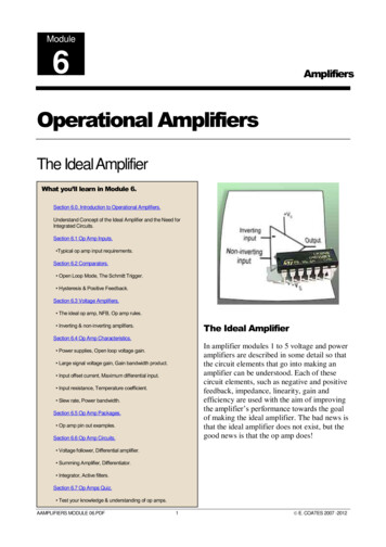
Op Amp Amplifier BasicsO There are two basics forms inwhich an Op Amp (OperationalAmplifier) can be used as anamplifier:O Inverting configurationO Non-inverting configuration
741 DIP Pinout Diagram
Non-inverting Op AmpSchematic
Practical Considerations forthe 741 Non-inverting Op AmpO The input bias current isabout 80 nAO The input offset current isabout 10 nAO The input impedance is about2 Meg Ohms
O The common mode voltage shouldbe within /-12V for /-15V supplyO The output impedance is about 75ohms.O The voltage gain rolls off 6dB peroctave starting at 100kHz.O Maximum output Current: 20mA
O There is a finite input offset whichmust be zeroed by a resistorbetween pins 1 and 5. The inputoffset is typically 2mV to 6mV.O The slew rate is 0.5V/microsecond.O There is some temperaturedependence
O Positive input voltages yield positiveoutput voltagesO Negative input voltages yieldnegative output voltagesO Thus, the non-inverting amplifierdoes not invert the phase of theinput signalO The feedback voltage will have thesame polarity and amplitude
O The voltage between the two inputterminals of a normally operating OpAmp is always zero volts.O The maximum output-voltage swing ofan Op Amp should ideally be equal tothe value of the applied voltage.O The actual maximum output swing ofthe 741 Op Amp is actually a little lessthan the theoretical maximum.(Applied Voltage)
O The op amp will no longer operatelinearly if you try to exceed this valueO The accuracy of the circuits to meetthe calculated values is dependenton the actual values of thecomponents used. (Values with theirtolerances)
O Remember resistors have atolerance.O The calculated gain of the amplifierwill very likely be different than themeasured gain.O This is true for capacitors and prettymuch any component manufacturedby man.
Voltage Gain of Non-invertingOperational AmplifierO The voltage gain can easily bedetermined in two waysO Calculation; using the followingformula: 𝐴V 1 𝑅𝐹𝑅1O Measurement by calculation:O 𝐴V Eout / EIn
Non-inverting Op AmpSchematic
1436 Fig 2 Constructed
1436 Fig 2 Ckt 1 Close-up
Gain for Non-inverting Op Ampsin Circuit 2O Voltage Gain is AVO Formula for the theoretical voltagegain for each RF to R1 combinationin a Non-inverting Op Ampconfiguration.O AV 1 RF/R1
Measured AV FormulaO AV EOUT/EIN or VOUT/VINO The output voltage, of Circuit 2 inExperiment 1, is supposed to beset to 2.5V for all values of theresistances.
Additional DiscussionO Remember: the theoretical andmeasured Voltage Gains can varyas much as 20% due to theresistor tolerances.O It is not unusual to see gainsfrom 1 to approximately 11 withthe values of resistances used.
Schematic for circuit 2 Exp. 1
1436 Exp 1, Ckt. 2, Fig 5 Close-up
Meter Isolation Ckt for Ckt 2
QUESTIONS?
ResourcesO Lesurf, J. (n.d.). Unpublished raw data,University of St. Andrews, St. Andrews,Scotland. Retrieved from http://www.standrews.ac.uk/ www pa/Scots Guide/datasheets/Opamps/741.htmlO Nave, R. (n.d.). The 741: Practicalconsiderations. Retrieved tronic/a741p.html
O Rosenow. (2001). Lesson 1436:Operational amplifier characteristics.Cleveland: Cleveland Institute ofElectronics.
The EndDeveloped and Produced bythe Instructors in the CIEInstruction Department. Copyright 01/2012All Rights Reserved / Jan. 2012
Jan 24, 2012 · Op Amp Amplifier Basics OThere are two basics forms in which an Op Amp (Operational Amplifier) can be used as an amplifier: OInverting configuration ONon-inverting configuration . 741 DIP Pinout Diagram . Non-