Transcription
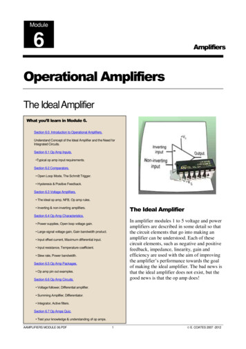
Application ReportSBOA092B –October 2001 –S Revised September 2016HANDBOOK OF OPERATIONAL AMPLIFIERAPPLICATIONSBruce Carter and Thomas R. BrownABSTRACTWhile in the process of reviewing Texas Instruments applications notes, including thosefrom Burr-Brown – I uncovered a couple of treasures, this handbook on op ampapplications and one on active RC networks. These old publications, from 1963 and1966, respectively, are some of the finest works on op amp theory that I have ever seen.Nevertheless, they contain some material that is hopelessly outdated. This includeseverything from the state of the art of amplifier technology, to the parts referenced in thedocument – even to the symbol used for the op amp itself:These numbers in the circles referred to pin numbers of old op amps, which were pottedmodules instead of integrated circuits. Many references to these numbers were made inthe text, and these have been changed, of course.In revising this document, I chose to take a minimal approach to the material out ofrespect for the original author, – Thomas R. Brown, leaving as much of the originalmaterial intact as possible while making the document relevant to present day designers.There were some sections that were deleted or substantially changed: “Broadbanding” operational amplifier modules – replaced with discussion of uncompensatedoperational amplifiers. Open loop applications and Comparators – Applications showing an operational amplifierused open loop, as a comparator have been deleted. At the time of original publication,there were no dedicated comparator components. Good design techniques now dictateusing a comparator instead of an operational amplifier. There are ways of safely using anoperational amplifier as a comparator – if the output stage is designed to be used that way as in a voltage limiting operational amplifier – or if clamping is added externally thatprevents the output from saturating. These applications are shown. Testing Operational Amplifiers – a section that had become hopelessly outdated. Testingtechniques are now tailored to the individual amplifier, to test for parameters important to itsintended purpose or target end equipment.1Search for TI op amps and technical resources
SBOA092B Some other application circuits were eliminated – if they were deemed impractical in thelight of today’s technology.This handbook has also been reorganized to eliminate some redundancy, and place allapplication circuits in one location.The reader is cautioned that proper decoupling techniques should be followed withoperational amplifiers. Decoupling components are omitted from applications schematicsin this document for clarity. Consult reference 2 for proper decoupling techniques.I also cleaned up grammatical and spelling mistakes in the original.--- Bruce Carter, Texas Instruments Applications(Excerpts from) Thomas Brown’s original Preface:The purpose of this handbook is to provide a single source of information covering the properdesign of circuits employing the versatile modem operational amplifier. This manual will behelpful to the experienced user of operational amplifiers, as well as the new user, in extendingthe range of potential applications in which these devices can be used to advantage.It is assumed that the reader will have a basic knowledge of electronics, but no particularknowledge of operational amplifiers is needed to use this handbook. The operational amplifier istreated as a circuit component inherently subject to certain rules of operation. The design of theoperational amplifiers themselves is considered only when necessary to describe their lessevident properties.Readers with a working knowledge of operational amplifiers will want to refer directly to thecircuit collection. Readers whose job functions have not previously brought them in contact withoperational amplifiers will want to proceed directly through the handbook until the desired degreeof familiarity is obtained.Refinements are continuously being made in the design and application of operationalamplifiers, yet the basic principles of application remain the same. Please do not hesitate tocontact Texas Instruments at any time with questions or comments arising from the use of thishandbook. It is, after all, intended for you, the user.--- Thomas R. Brown, Jr.2HANDBOOK OF OPERATIONAL AMPLIFIER APPLICATIONSSearch for TI op amps and technical resources
SBOA092BContentsINTRODUCTION. 7Computation Control Instrumentation . 7The Feedback Technique . 7Notation and Terminology. 8Input Terminals. 9Output Terminals . 9Power Connections . 10Summary of Notation . 10Electrical Circuit Models . 10Circuit Notation . 11The Ideal Operational Amplifier . 12Defining the Ideal Operational Amplifier. 12A Summing Point Restraint. 13CIRCUITS AND ANALYSES USING THE IDEAL OPERATIONAL AMPLIFIER . 14The Desirability of Feedback . 14Two Important Feedback Circuits . 15Voltage Follower. 15Non-Inverting Amplifier . 17INVERTING AMPLIFIER . 18Intuitive Analysis Techniques. 19Current Output. 20Reactive Elements. 20Integrator . 21Differentiator. 21Voltage Adder. 23Scaling Summer . 23Combining Circuit Functions . 24Differential Input Amplifier. 24Balanced Amplifier. 25Ideal-Real Comparison . 27CHARACTERISTICS OF PRACTICAL OPERATIONAL AMPLIFIERS. 29Open Loop Characteristics . 29Open Loop Operation . 30Output Limiting . 30FREQUENCY DEPENDENT PROPERTIES . 31Introduction. 31Open Loop Gain and the Bode Plot . 31Bode Plot Construction . 31Closed Loop Gain. 32Stability. 33Compensation . 33Compensation Changes . 34Bandwidth. 35Loop Gain. 35The Significance of Loop Gain. 36BODE PLOTS AND BASIC PRACTICAL CIRCUITRY. 37Voltage Follower. 37HANDBOOK OF OPERATIONAL AMPLIFIER APPLICATIONSSearch for TI op amps and technical resources3
SBOA092BInverter . 37X1000 Amplifier . 38Differentiator. 38INTEGRATOR. 40OTHER IMPORTANT PROPERTIES OF OPERATIONAL AMPLIFIERS. 41Summing Point Restraints . 41Closed Loop Impedance Levels. 42Output Impedance . 42Input Impedance. 43Differential Inputs and Common Mode Rejection. 44The Common Mode Voltage Limit . 44Offset. 44Drift 45Capacitive Loading . 45VOLTAGE DETECTORS AND COMPARATORS . 46Voltage Limiting Operational Amplifiers . 46THE VOLTAGE FOLLOWER . 49BUFFERS AND ISOLATION AMPLIFIERS . 50Inverting Buffer Adjustable Gain . 50Balanced Output. 50VOLTAGE AND CURRENT REFERENCES. 50Isolated Standard Cell . 51Constant Current Generator . 51Buffer Variation. 52Presettable Voltage Source . 52Reference Voltage Supply . 52THE NON-INVERTING AMPLIFIER . 53THE INVERTING AMPLIFIER . 54INTEGRATORS . 55PRACTICAL INTEGRATORS. 55Simple Integrators . 56Summing Integrator . 58Double Integrator. 58Differential Integrator . 59AC Integrator . 59Augmenting Integrator . 59DIFFERENTIATORS. 61With “Stop” . 61Low Noise . 62Augmented Differentiator. 62THE VOLTAGE SUMMER . 63SUMMING AND AVERAGING AMPLIFIERS. 64Adder. 64Scaling Adder . 64Direct Addition . 65Averager. 65Weighted Average . 66THE DIFFERENTIAL INPUT AMPLIFIER. 67Adder-Subtractor or Floating Input Combiner . 684HANDBOOK OF OPERATIONAL AMPLIFIER APPLICATIONSSearch for TI op amps and technical resources
SBOA092BTHE DIFFERENTIAL (BALANCED) OUTPUT AMPLIFIER. 69DC AMPLIFIERS . 70Simple Inverting sign changing amplifier. 70Chopper Stabilized . 70Simple Gain Control. 70Linear Gain Control . 71Simple Non-Inverting . 71Power Booster . 71Differential Output. 73Gain Control . 73Inverting Gain Control. 73DIFFERENTIAL AMPLIFIERS . 74Subtractor. 74Difference Amplifier . 74Common Mode Rejection . 75Differential Input-Output. 75AC AMPLIFIERS . 76DC Amplifiers with Blocking Capacitors . 76Simple Amplifier .76Single Supply .76Non-Inverting .77Double Rolloff .77AC Preamplifier .78CURRENT OUTPUT DEVICES. 79Feedback Loop. 79Simple Meter Amplifier. 79Meter Amplifier . 80Current Injector. 80Linear Current Source . 81Deflection Coil Driver . 82OSCILLATORS AND MULTI VIBRATORS . 83Simple Oscillator. 83Wien Bridge Oscillator . 83PHASE LEAD AND LAG NETWORKS . 84Lag Element . 84Adjustable Lag. 84Lag value linear with R setting . 85Adjustable Lead. 85Lead-Lag . 86Time Delay . 86ADDITIONAL CIRCUITS . 87Absolute Value . 87Peak Follower. 87Precision Rectifier. 88AC to DC Converter. 88Full Wave Rectifier . 89Rate Limiter . 89Time Delay . 90Selective Amplifier . 91SECTION III: SELECTING THE PROPER OPERATIONAL AMPLIFIER . 92HANDBOOK OF OPERATIONAL AMPLIFIER APPLICATIONSSearch for TI op amps and technical resources5
SBOA092BFocus on Limiting Specifications. 92Avoid Closed Loop vs. Open Loop Confusion. 92Selection Check List . 92Assistance Available from Texas Instruments. 93References. 93Figure 1.Figure 2.Figure 3.Figure 4.Figure 5.Figure 6.Figure 7.Figure 8.Figure 9.Figure 10.Figure 11.Figure 12.Figure 13.Figure 14.Figure 15.Figure 16.Figure 17.Figure 18.Figure 19.Figure 20.Figure 21.Figure 22.Figure 23.Figure 24.Figure 25.Figure 26.Figure 27.Figure 28.Figure 29.Figure 30.Figure 31.Figure 32.Figure 33.Figure 34.Figure 35.Figure 36.Figure 37.Figure 38.Figure 39.Figure 40.Figure 41.6FiguresOperational Amplifier with Feedback . 8Texas Instruments Standard Symbols . 8Op Amp Package Options . 9Power Supply Connections. 10Summary of Notation Introduced. 10Circuit Model of the Single Ended Operational Amplifier . 10Circuit Model of the Differential Output Operational Amplifier. 11Notation and Terms Used in Closed Loop Circuits . 11Equivalent Circuit of the Ideal Operational Amplifier . 12Open Loop Operation . 14Basic Amplifier Circuits. 15Voltage Follower . 15Feedback Resistor Added to the Voltage Follower . 16Non-Inverting Amplifier . 17Non-Inverting Amplifier Re-Drawn to Show Similarity to the Voltage Follower. 17Non-Inverting Amplifier Analyzed as a Voltage Divider . 17Inverting Amplifier . 18Intuitive Devices for Analysis of Circuits Based on the Inverting Amplifier. 19Inverting Amplifier as a Linear Current Output Device . 20General Form of the Inverting Amplifier. 20Integrator Circuit. 21Differentiator Circuit . 21An Intuitive Picture of the Differentiator. 22Voltage Adding Circuit . 23Scaling Summer Circuit. 24Differential Input Amplifier Circuit . 24Analyzing the Differential Input Amplifier Circuit as Non-Inverting Amplifier . 25The Differential Output Operational Amplifier . 26Equivalent Circuit of a Real Operational Amplifier . 27Amplifier Circuit Using a Real Operational Amplifier . 27Input-Output Transfer Relation for the Open Loop Operational Amplifier. 29Bode Plot of an Operational Amplifier and its Linear Approximation . 31Sketching the Bode Plot Approximation for Figure 32. 32Closed Loop Gain of a X100 (40 dB) Inverting Amplifier. 32The Effect of Internal Phase Compensation. 33Composite Bode Plots Showing Stability Provided by Proper Phase Compensation34The Effect of Internal Compensation for Gains Greater Than 1. 34Instability when an Uncompensated Amplifier is Used at Gains Lower Than theDesignated Level.
operational amplifier as a comparator – if the output stage is designed to be used that way - as in a voltage limiting operational amplifier – or if clamping is added externally that prevents the output from saturating. These applications are shown.