Transcription
Application ReportSBOA093A – October 2001Handbook Of Operational Amplifier Active RC NetworksBruce Carter and L.P. HuelsmanABSTRACTWhile in the process of reviewing Texas Instruments applications notes, including thosefrom the recently acquired Burr-Brown – I uncovered a couple of treasures, this handbookon active RC networks and one on op amp applications. These old publications, from1966 and 1963, respectively, are some of the finest works on op amp theory that I haveever seen. Nevertheless, they contain some material that is hopelessly outdated. Thisincludes everything from the state of the art of amplifier technology, to the partsreferenced in the document – even to the symbol used for the op amp itself:These numbers in the circles referred to pin numbers of old op amps, which were pottedmodules instead of integrated circuits. Many references to these numbers were made inthe text, and these have been changed, of course.In revising this document, I chose to take a minimal approach to the material out ofrespect for the original author - L.P. Huelsman, leaving as much of the original material intact as possible while making the document relevant to present day designers. I did cleanup grammatical and spelling mistakes in the original. I even elected to leave the originalRC stick figure illustrations, which have minimal technical content – but added to thereadability of the document.1
SBOA093AContentsCHAPTER 1. 6Introduction. 6CHAPTER 2. 11The Infinite-Gain Single-Feedback Circuit . 11The Operational Amplifier . 11The Basic Single Feedback Circuit . 12The Voltage Transfer Function . 13The Passive Networks. 16Network Design . 18Conclusions. 20CHAPTER 3. 21The Infinite-Gain Multiple-Feedback Circuit . 21The Basic Multiple Feedback Circuit. 21The Voltage Transfer Function . 21Network Design . 23Conclusions. 26CHAPTER 4. 27The Controlled Source Circuit. 27The Voltage-Controlled Voltage Source. 27Network Design . 28Other Realizations with Voltage-Controlled Voltage Sources. 33Conclusions. 34CHAPTER 5. 36The NIC In Active RC Circuits. 36The NIC (Negative-Immittance Converter). 36A Realization for the INIC . 38Stability of the INIC. 39The Basic INIC Circuit . 40Network Design . 41Conclusions. 44CHAPTER 6. 45Another Active Device: The Gyrator. 45Definition of a Gyrator. 45Properties of the Gyrator . 45A Gyrator Realization . 46Circuit Realizations. 47Conclusions. 48CHAPTER 7. 49A Summary. 49SECTION II . 51Circuits . 51Introduction. 51APPENDIX A . 80References. 80Chapter 1 . 802Handbook Of Operational Amplifier Active RC Networks
SBOA093AChapter 2. 80Chapter 3. 80Chapter 4. 81Chapter 5. 81Chapter 6. 81APPENDIX B . 82Describing Active Filters . 82Describing the Filter. 82Optimizing the Circuit. 82Limiting Specifications . 82Conclusion. 83APPENDIX C . 84FiguresFigure 1-1. Model for an Ideal Operational Amplifier . 9Figure 1-2. Circuit Symbol for an Operational Amplifier . 9Figure 2-1. Symbolic Representation of the Operational Amplifier . 11Figure 2-2. Open-Loop Transfer Characteristics of the Operational Amplifier . 11Figure 2-3. Open Loop Frequency Characteristic of a Typical Operational Amplifier. 12Figure 2-4. Basic Single Feedback Operational Amplifier Circuit. 12Figure 2-5. The Port Variables for Network A.13Figure 2-6. The Port Variables for Network B.13Figure 2-7. The Port Variables for the Basic Single-Feedback Circuit. 14Figure 2-8. Dual Summing Single-Feedback Circuit . 15Figure 2-9. Bridged-T RC Network . 16Figure 2-10. Twin-T RC Network. 17Figure 2-11. Low Pass Network A . 18Figure 2-12. High Pass Network A. 19Figure 2-13. Single Zero – Single Pole Network A . 19Figure 3-1. Multiple-Feedback (MFB) Operational Amplifier Circuit . 21Figure 3-2. Basic Multiple-Feedback Circuit. 22Figure 3-3. Low Pass MFB Filter . 23Figure 3-4. High Pass MFB Active Filter . 24Figure 3-5. Band Pass MFB Active Filter . 25Figure 4-1. VCVS Circuit Model . 27Figure 4-2. VCVS Circuit Symbol . 27Figure 4-3. Non-Inverting Operational - Amplifier VCVS . 28Figure 4-4. VCVS Low Pass Active Filter . 29Figure 4-5. Operational Amplifier VCVS Low Pass Active Filter . 30Figure 4-6. VCVS High Pass Active Filter . 31Figure 4-7. Operational Amplifier VCVS High Pass Active Filter . 31Figure 4-8. VCVS Band Pass Active Filter . 32Figure 4-9. Inverting Operational Amplifier VCVS. 33Figure 4-10. Inverting VCVS Low Pass Filter.33Figure 4-11. Inverting VCVS High Pass Filter. 34Figure 5-1. Two-Port Network With Load. 36Figure 5-2. The Port Variables for a Two-Port Network . 36Figure 5-3. INIC Input Circuit . 37Figure 5-4. INIC Output Circuit . 37Handbook Of Operational Amplifier Active RC Networks3
SBOA093AFigure 5-5. Operational Amplifier Realization of the INIC. 38Figure 5-6. Circuit Model of the Operational Amplifier Realization INIC . 39Figure 5-7. Basic Voltage Transfer Circuit Using the INIC . 40Figure 5-8. INIC Low Pass Active Filter . 41Figure 5-9. INIC High Pass Active Filter. 42Figure 5-10. INIC Band Pass Active Filter. 43Figure 6-1. Gyrator Symbol . 45Figure 6-2. The Input Admittance of a Terminated Two-Port Network . 46Figure 6-3. Gyrator Realization Using Two INIC’s. 47Figure 6-4. Gyrator Band Pass Active Filter . 47CIRCUIT 1: Single Feedback Low Pass . 52CIRCUIT 2: Single Feedback High Pass . 54CIRCUIT 3: Single Feedback Band Pass . 56CIRCUIT 4: Multiple Feedback Low Pass . 59CIRCUIT 5: Multiple Feedback High Pass. 62CIRCUIT 6: Multiple Feedback Band Pass. 64CIRCUIT 7: Controlled Source Low Pass . 66CIRCUIT 8: Controlled Source High Pass. 68CIRCUIT 9: Controlled Source Band Pass. 71CIRCUIT 10: INIC Low Pass . 73CIRCUIT 11: INIC High Pass . 75CIRCUIT 12: INIC Band Pass . 78Table 1.4TablesSummary of the Advantages and Disadvantages of the Various RealizationTechniques . 49Handbook Of Operational Amplifier Active RC Networks
SBOA093AACTIVE RC NETWORK THEORYThe subject of active RC networks is one that has attracted considerable attention in thepast few years from network theorists. Many new active devices and many newtechniques have been developed. Some of these techniques have been of greattheoretical interest, but of little practical value. Others, however, offer great practicalityand have great potential for everyday application. In writing this hand- book, the goal hasbeen to screen the large volume of literature on this subject, and present only thosetechniques that are of definite practical value to the working engineer. All of therealization schemes described in Chapters 2 through 5 have been proven on the bench,and full details on their implementation are given in the “circuits” section of this handbook.In addition, each of these techniques is described in the text, where some of the pertinenttheoretical background is given. The reader who is interested in a more detailedtheoretical treatment will find that the references listed in Appendix A will give him anexcellent introduction into the considerable literature on this subject.Handbook Of Operational Amplifier Active RC Networks5
Application ReportSBOA093A – October 2001CHAPTER 1IntroductionThis is a handbook on active RC networks. The first question about this subject that one mightask is, "What is an active RC network?” The answer is simple. It is collection of resistors,capacitors, and an active element (or elements). Viewed in another sense; it is a circuit withoutinductors. Why leave out inductors? There are many reasons. First of all, the inductor is arelatively large and heavy element. This is especially true at frequencies in the audio range andbelow.Second, inductors generally have more dissipation associated with them than capacitors ofsimilar size. In other words, commercially available inductors are not nearly as “ideal" ascommercially available capacitors. If you have tried to use network synthesis techniques youhave probably discovered that the dissipation (or resistance) associated with inductors cancause considerable difficulty. For these reasons (and a few others such as non-linearity,saturation, and cost) more and more interest is being shown in circuit design techniques whichavoid the use of inductors, namely active RC networks.6
SBOA093ACan active RC networks do everything that passive RLC networks can do? Yes, and more!They can have natural frequencies any place in the left half at the complex frequency (or "s")plane. They can function as oscillators, in other words they can have natural frequencies on thejω axis. They can provide transformation ratios just like the coupled coils of a transformer do(however they can’t provide the isolation). They can even provide perfect coupling and thusrealize "ideal" transformers, which actual coupled coils cannot do. They can gyrate microfaradsof capacitance into hundreds of henries of inductance, etc. There won't be space in thishandbook to cover all of the things that active RC networks can do. Instead, we'll try to show youin detail how to use them to do some of your more common filtering tasks. If you are interestedin more specialized applications, some references are given in Appendix A.Natural Frequencies for Passive RC CircuitsHow does the tremendous capability of active RC networks come about? Certainly not from thepassive elements, the resistors and capacitors. Taken by themselves these elements canproduce natural frequencies only on the negative real axis of the complex frequency plane, arelatively uninteresting region for most filtering applications. Active RC networks, on the otherhand, can have natural frequencies anywhere on the complex frequency plane. Right half planenatural frequencies, of course, are not useful because they signify unstable network behavior, sowe'll just consider the usable active RC natural frequencies as being in the left half plane or onthe jω axis. Since it is the "active” element that gives active RC networks their potential, let'sbriefly consider such elements in more detail.Handbook Of Operational Amplifier Active RC Networks7
SBOA093AStable Natural Frequencies for Active RC CircuitsThere are several types of active elements that can be used in active RC networks. First, thereis the ideal voltage amplifier of high gain. By “high" here we mean a gain in the order of at least60db. By "ideal" we mean infinite input impedance and zero output impedance. The operationalamplifier is an example of such an active element. Second, there is the ideal voltage amplifier oflow gain. By "low” here we mean a gain in the order of 20 db or less. Such an element issometimes referred to as a controlled source.Third, there is the NIC (negative-immittance converter, also sometimes referred to as a negativeimpedance converter). This is a two-port device (a device with two sets of terminal pairs) withthe property that impedance connected across one set of terminals appears as negativeimpedance at the other set of terminals. Fourth, there is the gyrator, a device that convertscapacitance to inductance and vice versa.8Handbook Of Operational Amplifier Active RC Networks
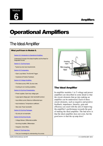
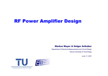
SBOA093AAn interesting point to be noted here is that any of the last three types of active elements listedabove can also be realized very simply and accurately with operational amplifiers. Thus, we seethat the operational amplifier can be considered as a basic building black for constructing everytype of active RC network. Many more details about the active elements introduced above willbe given in the sections that follow. The networks that use operational amplifiers to realize theseactive elements will also be discussed. First, however, let us say a few things about theoperational amplifier.The modern differential input operational amplifier may be simply modeled as an ideal voltageamplifier of very low output impedance (we'll assume that it is zero), very high input impedance(we'll assume that it is infinite), and very high gain, with the property that the output voltage isproportional to the difference in the voltages applied to the two input terminals. An equivalentcircuit for such a model is shown in Figure 1-1.Figure 1-1. Model for an Ideal Operational AmplifierThe circuit symbol that will be used in future discussions is shown with the same terminaldesignation in Figure 1-2: Figure 1-2. Circuit Symbol for an Operational AmplifierHandbook Of Operational Amplifier Active RC Networks9
SBOA093AAs a result of the properties of the operational amplifier, when it is inserted in circuitconfigurations, the voltage between the input terminals - and in Figures 1-1 and 1-2 is drivento zero. Due to the high input impedance and zero voltage, the current into both of theseterminals may be considered as zero. These two characteristics comprise the "virtual ground"concept that is a basic tool for analyzing operational amplifier circuits. For more detailedinformation on the properties and characteristics of operational amplifiers, you should consult the"Handbook of Operational Amplifier Applications", SBOA092, which is available from TexasInstruments.In the remainder of this handbook, we shall discuss in detail how the various types of activeelements introduced above may be used to produce the most common types of networkcharacteristics, namely, the low-pass, the high-pass, and the band-pass characteristics. Weshall see that each of the active elements has advantages and disadvantages in the differentcircuit configurations. So, without more delay, let us start our investigation of active RCnetworks, a world without inductors.10Handbook Of Operational Amplifier Active RC Networks
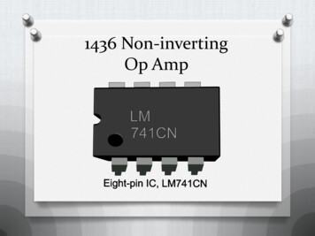
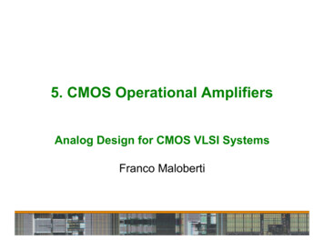
Application ReportSBOA093A – October 2001CHAPTER 2The Infinite-Gain Single-Feedback CircuitThe first active element that we shall consider for realizing active RC networks is the operationalamplifier. In this chapter we shall investigate its use directly as an operational amplifier, in otherwords we shall not first modify it so that its characteristics approach those of some other activedevice. It may be helpful at this point to review briefly some of the characteristics of theoperational amplifier. Those readers who are familiar with operational amplifiers may skip thenext section without loss of continuity.The Operational Amplifier- E1- E2- Eo-Figure 2-1. Symbolic Representation of the Operational AmplifierIn Figure 2-1 we have shown a symbolic representation for an operational amplifier that definesthe input voltages E1 and E2 and the output voltage Eo. In terms of these voltages we may plot atypical open-loop DC transfer characteristics as shown in Figure 2-2.Figure 2-2. Open-Loop Transfer Characteristics of the Operational AmplifierFrom this figure we see that the “-“ terminal may be referred to as the "inverting" input terminal,while the “ ” terminal may be referred to as the "non-inverting" input terminal. In a typicaloperational amplifier the magnitude of Eo is near the power supply rails at saturation. The openloop DC gain of the amplifier shown in Figure 2-3 is 100000, so we see that the magnitude of Es,the differential input voltage that produces saturation, is only 100 µV. Therefore, open-loopoperation of an operational amplifier is not practical. The open-loop frequency characteristic of atypical operational amplifier is shown in Figure 2-3.11
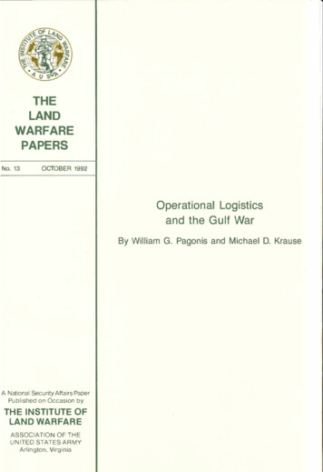
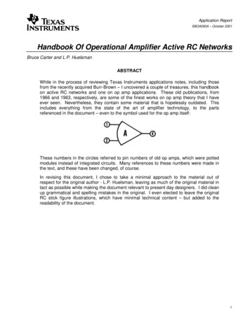
SBOA093AFigure 2-3. Open Loop Frequency Characteristic of a Typical Operational AmplifierThe slope of the roll-off is 20 dB/decade. A compensation network determines the location ofthe break point. In most voltage feedback operational amplifiers, this network is integral with theoperational amplifier circuitry; in uncompensated amplifiers, the designer must supply it externalto the amplifier packaging. Stability considerations determine the proper choice of compensationnetwork for a given circuit configuration; however, most operational amplifiers are compensatedso as to provide adequate performance for the majority of circuit applications. For additionalinformation on stability, compensation, or other general properties of operational amplifiers, thereader is referred to the "Handbook of Operational Amplifier Applications", SBOA092, publishedby Texas Instruments.The Basic Single Feedback CircuitThe basic circuit that will be considered in this chapter consists of two passive networks, whichwe will refer to as network A and network B, and an operational amplifier. Network A isconnected between the input to the circuit and the input terminal of the operational amplifierNetwork B is used as a feedback network from the output to the input of the operationalamplifier. The circuit is shown in Figure 2-4.NetworkB NetworkA E1E2--Figure 2-4. Basic Single Feedback Operational Amplifier CircuitIt should be noted that the operational amplifier is used in an inverting configuration, i.e., with itsnon-inverting input terminal ( ) grounded. We shall call this circuit an infinite-gain singlefeedback circuit since the operational amplifier that is the active element normally has very highgain, and since the feedback around it is made to a single point.12Handbook Of Operational Amplifier Active RC Networks
SBOA093ATo characterize the properties of the two passive networks, we shall use their yparameters. For network A, we may define voltage and current variables as shown inFigure 2-5.I2aI1a YijaE1a E2a--Figure 2-5. The Port Variables for Network AThe relations between these variables and the y parameters of the network are:I1a y 11aE1a y12aE 2aI 2a y 12aE1a y 22aE 2a(1)Similarly, for network B and the variables shown in Figure 2-6:I2bI1b E1b-Yijb E2b-Figure 2-6. The Port Variables for Network BI1b y11bE1b y12bE 2bI2b y12bE1b y 22bE 2b( 2)All of the voltage and current variables and the y parameters defined in equations (1) and(2) are functions of "s", the complex frequency variable.The Voltage Transfer FunctionThe basic network configuration for the infinite-gain single-feedback circuit has been redrawn inFigure 2-7 to indicate the variables of the two passive networks explicitly.Handbook Of Operational Amplifier Active RC Networks13
SBOA093AI2bI1b YijbE1b- E2b-I2aI1aYija - E1E1aE2aE2---- Figure 2-7. The Port Variables for the Basic Single-Feedback CircuitIn Chapter 1, it was pointed out that due to the "virtual ground," the voltage between theinverting and non-inverting terminals of the operational amplifier may be considered to be zero.Thus, the voltage E2a shown in Figure 2-7 is zero. From the second equation of (1), we see thatunder this condition I2a y12aE1a . In addition, since E1a and E1 are equal, we may write:I2a y12aE1(3)Similarly, for network B, E1b is zero, and E2b E2. Thus we see that:I1b y12bE 2(
Handbook Of Operational Amplifier Active RC Networks Bruce Carter and L.P. Huelsman ABSTRACT While in the process of reviewing Texas Instruments applications notes, including those from the recently acquired Burr