Transcription
MUTCD: Roadway PavementMarkingsCourse No: C06-015Credit: 6 PDHGregory J. Taylor, P.E.Continuing Education and Development, Inc.9 Greyridge Farm CourtStony Point, NY 10980P: (877) 322-5800F: (877) 322-4774info@cedengineering.com
INTRODUCTIONThis course discusses how to effectively use pavement markings to guide roadway traffic,and thereby reduce your liability exposure. The contents of this course are intended toserve as guidance and not as an absolute standard or rule. Its purpose is to help you to usethe Manual on Uniform Traffic Control Devices (MUTCD) – Parts 3, 5, 7, 8 and 9 moreeffectively and not replace it. Should there be any discrepancies between the contents ofthis course and the MUTCD - always follow the MUTCD.Upon course completion, you should be familiar with the general design guidelines forpavement markings. The course objective is to give engineers and designers an in-depthlook at the principles to be considered when selecting and designing for traffic control.For this course, the Manual on Uniform Traffic Control Devices for Streets and Highways(MUTCD) 2009 Edition will serve as a reference for the fundamental design principles ofpavement markings. The MUTCD is recognized as the national standard for all trafficcontrol devices installed on any street, highway, bikeway, or private road open to publictravel. Any traffic control device design or application contained within it is considered tobe in the public domain and available for dition.pdf
Roadway Pavement MarkingsPavement markings are typically used for conveying laws and regulations, traffic androadway conditions, and guidance and other information. These critical tools provideimportant information for safe travel on any U.S. roadway system.Roadway pavement markings are not a cure for all traffic problems. Road users processdifferent types of visual and non-visual information differently: speed, roadway conditions,traffic, legal enforcement, noise levels, etc. Also, markings serve as reminders of importantinformation, so road users do not have to memorize everything.The goal is to provide drivers with relevant information when they need it - resulting insafer, more efficient roadways with reduced liability risks. However, roadway pavementmarking management can greatly reduce safety, contribute to roadway incidents, andincrease liability exposure.The Standard Highway Signs and Markings book contains detailed specifications for alladopted standard signs and pavement markings. All traffic control devices have to besimilar to or mirror images of those shown in this manual. Any symbols or colors cannot bemodified unless otherwise stated.http://mutcd.fhwa.dot.gov/SHSe/shs 2004 2012 sup.pdfCopyright 2015Gregory J. Taylor, P.E.Page 2 of 64
Roadway Pavement MarkingsMANUAL ON UNIFORM TRAFFIC CONTROL DEVICES (MUTCD)By law (23 CFR 655, Subpart F), the Manual on Uniform Traffic Control Devices (MUTCD) isrecognized as “the national standard for all traffic control devices installed on any street,highway, bikeway, or private road open to public travel”. It is the definitive authority fortraffic signs and pavement markings.Nationwide consistency is the goal of the MUTCD by requiring uniform, understandable,and effective traffic control devices on all facilities open to public travel. It defines thenationwide standards for the installation and maintenance of the devices on all streets andhighways. The MUTCD allows us to drive anywhere in the U.S. using the same basic signsand pavement markings with the same meanings. Drivers who see a particular markingshould expect it to mean the same thing regardless of location.The Federal Highway Administration (FHWA) publishes the MUTCD which establishesuniform standards for traffic control devices and promotes safety and efficiency on publicroads. Road safety can be greatly increased by exceeding MUTCD requirements. Excessivemethods should only be employed if a standard measure cannot meet the need. Otherwise,road users may tend to disregard the traffic control device.Copyright 2015Gregory J. Taylor, P.E.Page 3 of 64
Roadway Pavement MarkingsThe MUTCD has nine chapters (“Parts”) but since this course concentrates primarily on thesubject of roadway pavement markings, we will focus mainly on Parts 3, 5, 7, 8 and 9.1. General2. Signs3. Marking4. Highway Traffic Signals5. Traffic Control Devices for Low-Volume Roads6. Temporary Traffic Control7. Traffic Control for School Areas8. Traffic Control for Highway-Rail Grade Crossings9. Traffic Control for Bicycle FacilitiesSHALL, SHOULD, and MAYThe terms “shall,” “should,” and “may” have specific meanings when used in the MUTCD.SHALL – Required, mandatory or specifically prohibitive practice.Any statements with “shall” conditions are typically used as a STANDARD in theMUTCD. These items cannot be modified or compromised. There is no allowance fordiscretion and they must be followed.SHOULD – Advisory or recommended practice in typical situations.Deviation is appropriate if justified by engineering judgment or study. Statementsmarked as “should” are used for GUIDANCE in the MUTCD.MAY – Permissive or optional practice without requirement or recommendation.Items marked as “may” are typically used in OPTION statements in the MUTCD andcan contain allowable modifications.Copyright 2015Gregory J. Taylor, P.E.Page 4 of 64
Roadway Pavement MarkingsSUPPORT statements do not contain the verbs “shall”, “should”, or “may”. These statementsare for informational purposes only (without any mandate, recommendation, orenforcement).Road UserThe MUTCD defines a road user as “a vehicle operator, bicyclist, or pedestrian, includingpersons with disabilities, within the highway or on a private road open to public travel”. Thisgroup includes users of various skill levels and ages, pedestrians, wheelchairs, runners,rollerbladers, bicyclists, truck drivers, and motorcyclists. By meeting user needs, engineerscan minimize any problems that the average road user may encounter.FIVE BASIC REQUIREMENTS OF TRAFFIC CONTROL DEVICESIn order to be effective, any traffic control device has to be used in the right way. TheMUTCD lists the following principles to be used when selecting and applying each device:1 - Fulfill a needA device should only be installed if there is a need for warning, regulation or guideinformation. It is also vital to use markings that fulfill that need. If a need exists andthe sign in question does not meet that need, use something else. Overusingpavement markings can lead to disrespect and loss of emphasis value whileunderuse can result in persistent but correctable safety problems.2 - Command attentionStandard roadway markings are designed to be noticed and catch the attention ofroad users. The high-contrast color combinations were chosen due to their ability tostand out and be easy to read.Maintenance is the key to remain eye-catching. All markings need to be kept in goodworking order. They need to reflect light at night, and not be faded, cracked, orpeeling. Pavement markings in bad condition are unable to command attention, dayor night.3 - Command respectRoad users are expected to willingly obey warnings and regulations that obviouslyfulfill a need. Markings that seem unneeded or unreasonable are regularlydisobeyed. Good management and maintenance is crucial to commanding respectCopyright 2015Gregory J. Taylor, P.E.Page 5 of 64
Roadway Pavement Markingsfor traffic control devices. Amateurish, homemade or damaged pavement markingsare more likely to be disregarded.4 - Have one simple messageTraffic control devices need to communicate its message in a way that is clear andreadable. By using standard pavement markings in the MUTCD that have beenresearched and evaluated by the FHWA, most drivers should understand theirmeanings.5 - Provide adequate time for proper responseTraffic control devices should meet or exceed MUTCD standards so drivers haveadequate time (Perception-Response Time – PRT) to react. Drivers need to have thetime and distance to take the appropriate action before they reach a situation. If not,insufficient response time may result in roadway crashes.Traffic speed is an important factor for determining driver response time. Vehiclesoperating at high speeds need longer response time and more distance to react. Thisincreased distance can be obtained by placing pavement markings in advance of thelocation where the information is needed.Using the five basic requirements will help make your traffic control devices more effective.Design, placement, operation, maintenance, and uniformity should be taken intoconsideration to maximize the ability of a device to meet these principles. However, bydisregarding the five requirements, you may find that road users disregard your trafficcontrol devices.READIBILITY and RETROREFLECTIVITYDrivers must be able to read a traffic control devices from a reasonable distance and haveadequate reaction time to safely travel the roadway. As the national population gets older,the average driver gets older, and people continue driving at older ages. Improvingnighttime visibility of signs and pavement markings becomes more important as thetraveling public gets older. As we age, our eyes gradually become less light sensitive.Retroreflectivity is the ability of a traffic control device to reflect light from its surfaceback to its original source. Retroflective markings can be used for increasing nighttimevisibility. Maintaining retroreflectivity is a crucial element of traffic safety since fatal nightcrashes occur approximately three (3) times as often as daytime traffic fatalities.Copyright 2015Gregory J. Taylor, P.E.Page 6 of 64
Roadway Pavement MarkingsRetroreflectivity Elements Light source (vehicle headlights) Target (traffic control device) Receptor (driver’s eyes)Technologies involving glass beads or prismatic reflectors are more visible and bright sincemore light is reflected directly back to the original source.New materials or methods can be used as long as the traffic control devices meet thestandard color requirements. Pavement marking design should be uniform without anydecrease in:visibility,legibility, ordriver comprehension during day or night conditions.Copyright 2015Gregory J. Taylor, P.E.Page 7 of 64
Roadway Pavement MarkingsPAVEMENT MARKINGSPavement markings are more than roadway striping. They are part of a guidance systemfor relaying regulatory and vehicle-path information to the user - without requiring themto divert their attention from the road. Markings are used to encourage safe, orderly trafficflow and optimize roadway capacity. To be effective, pavement markings need to be readilyrecognized and understood. A uniform system of marking color, shape, and application hasbeen developed to convey the same message each time a pavement marking isencountered.All pavement markings should be properly maintained to ensure good daytime andnighttime visibility. Once a municipality has made the decision to install a marking, it istheir responsibility to maintain it. If the municipality decides that the marking is no longerneeded, documentation of the decision process should be recorded. Pavement markingsdeemed non-applicable or confusing should be removed as soon as yright 2015Separates traffic traveling in the same directionDelineates the right edge of the roadwaySeparates traffic flows in opposite directionsDelineates the left edge of divided/one-way highways and rampsDifferentiates two-way left-turn lanes and reversible lanes from otherlanesSupplements white markings for handicap parkingSupplements toll plaza approach lane lines or edgelines restricted forregistered electronic toll collection vehiclesUsed with other pavement markings (yellow, white, red, blue, orpurple) for light-colored pavements that do not providesufficient contrastGregory J. Taylor, P.E.Page 8 of 64
MATERIALSRoadway Pavement MarkingsThe color, pattern, and orientation of pavement markings provide crucial information toroadway users. Compliance with these standards is critical for providing positive guidanceand should be maintained throughout the useful life of the markings. Materials thatminimize tripping or loss of traction to pedestrians, bicyclists, motorcycles, etc. should beconsidered when choosing pavement markings.Pavement markings typically include paints and thermoplastics - but other markingmaterials (colored paving, raised pavement markers, etc.) may also be used. Highly visibledelineators and channelizing devices can also be installed similar to those methods forsigns.Paint is the easiest, cheapest, and most commonly used pavement marking material - but itis also the least durable. For poor nighttime visibility, retroreflectivity can be improved byadding glass beads into the wet paint.Thermoplastic pavement markings use temperature-setting plastics that are heated totheir melting point for use on asphalt paving. Due to the temperature-related expansionand contraction differentials between plastic and concrete (which can result inthermoplastic separation), thermoplastic is generally unsuitable for use on concretepaving.LONGITUDINAL MARKINGSLongitudinal markings are generally placed parallel and adjacent to traffic flow – lane lines,center lines, edge lines, channelizing lines, etc. These markings guide traffic along theroadway by providing visual clues to the travel path.Longitudinal Line Functions:Double Line:Solid Line:Broken Line:Dotted Line:Maximum or special restrictionsDiscourages or prohibits crossing (depends on application)Permissive conditionProvides guidance or warning of lane function changes aheadThe widths and patterns of longitudinal lines shall be as follows:Normal line - 4 to 6 inches wideCopyright 2015Gregory J. Taylor, P.E.Page 9 of 64
Roadway Pavement MarkingsWide line - minimum of twice the width of a normal lineThe line width indicates the degree of emphasis.Double line - two separated parallel linesBroken line - normal line segments (10 feet) separated by (30 feet) gapsDotted line - noticeably shorter line segments (2 feet) separated by shorter gaps(2 to 6 feet) when used for intersections and tapers - 3 feet linesegments with 9 feet gaps when used for lane lines. Line width is atleast the same as the width of the line it extends.White or yellow broken lines permit vehicles to pass or change lanes. As stated above,these markings are applied with ten foot painted dashes and thirty foot spacing. Therefore,the distance from the beginning of one dash to the beginning of the next dash is 40 feet. Byknowing this information, an individual can estimate distances along roadways veryquickly. For example, if there are three dashes between two side roads; then the estimateddistance equals 120 feet separating the roadways (3 x 40).YELLOW CENTER LINE PAVEMENT MARKINGS & WARRANTSYellow center line pavement markings separate opposite traffic lanes for roadways. Thesemarkings can be installed at locations that are not the exact center of the roadway. Shortsections on roads (without continuous center line markings) may be marked with centerline pavement markings to control traffic, where necessary - curves, hills, grade crossings,bridges, etc.Copyright 2015Gregory J. Taylor, P.E.Page 10 of 64
Roadway Pavement MarkingsCopyright 2015Gregory J. Taylor, P.E.Page 11 of 64
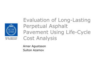
Roadway Pavement MarkingsCENTER LINE MARKING OPTIONS(Two-lane, two-way roadways)Two-direction passing zonesBroken yellow lines where passing with care is permitted by traffic in eitherdirection. Vehicles may pass.One-direction no-passing zonesDouble yellow line (broken and solid) where traffic may pass if traveling adjacent tothe broken line, but is prohibited if traveling adjacent to the solid line. Do not pass ifdriving next to the solid line.Two-direction no-passing zonesTwo solid yellow lines where crossing the center line is prohibited for traffictraveling in either direction. Never drive to the left of these lines.For undivided two-way roadways with four or more traffic lanes, the centerline markingswill be two-direction no-passing zone markings (double solid yellow lines). Markings ontwo-way roads with three through lanes will consist of one/two-direction no-passing zonemarkings that designate two lanes for one direction traffic.Copyright 2015Gregory J. Taylor, P.E.Page 12 of 64
Roadway Pavement MarkingsRequired Center Line Pavement MarkingsTraveled way 20 feet or widerADT 6000 vehicles/day or more**Paved two-way streets or highwaysThree or more lanesRural arterials & collectorsTraveled way 18 feet or widerADT 3000 vehicles/day or moreWhere engineering judgment indicates a needPaved urban arterials & collectors**May be used for a minimum ADT of 4000 vehicles/dayADT estimates based on engineering judgment may be used if traffic counts areunavailable. Center line markings may be placed on paved two-way roads with a minimumwidth of 16 feet.NO-PASSING ZONESNo-passing zones should be used on two- and three-lane roads (with center line markings)where engineering studies indicate that passing must be prohibited due to inadequate sightdistance or other special conditions.Typical No-Passing Zone Locations Lane reduction transitions Obstruction approaches (must be passed on right side) Grade crossings Highway-rail grade crossings Inadequate sight distance locationsThe MUTCD mandates using either one-direction or two-direction no-passing zonepavement markings. No-passing zone signs may be used in addition to markings foremphasizing the limits of a no-passing zone.One-direction no-passing zone markingsDouble yellow line – one normal broken and one normal solid.Passing is permitted for traffic adjacent to the broken line and prohibited for trafficadjacent to the solid line.Two-direction no-passing zone markingsDouble solid yellow lines that prohibit passing in either direction.Copyright 2015Gregory J. Taylor, P.E.Page 13 of 64
Roadway Pavement MarkingsPassing Sight Distance DefinitionsVertical Curve:Distance at which an object 3.5 feet (42 inches) above the pavement surface isvisible from a point 3.5 feet above the pavementHorizontal Curve:Distance along the centerline (right-hand lane line for 3-lane road) betweentwo points 3.5 feet above pavement on a line tangent to the embankment orobstruction that cuts off visibility on inside of curve.These values are for operational use and may be less than the geometricdesign values found in the AASHTO “Green Book”.No-passing markings are needed for connecting successive no-passing zones that are lessthan 400 feet apart.Copyright 2015Gregory J. Taylor, P.E.Page 14 of 64
Roadway Pavement MarkingsCopyright 2015Gregory J. Taylor, P.E.Page 15 of 64
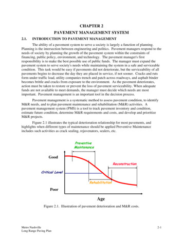
Roadway Pavement MarkingsUpstream point “a” is where the sight distance first becomes less than the minimumvalues. Downstream point “b” is the point where the sight distance is again greaterthan the minimum.For three-lane roadways with center lane transitions from one direction to the other, a nopassing buffer zone should be located in the center lane. This buffer should consist of aflush median island with two sets of double yellow center line markings - a minimumlength of 50 feet with lane-reduction transitions at each end. Yellow diagonal crosshatchmarkings can also be used in the flush median area between the two sets of no-passingzone markings.LANE TRANSITION TAPER LENGTHS(3-Lane Roadways)Speed LimitFormulaL WS²/60L WSLess than 45 mph45 mph or moreL Taper length (ft)W Center lane width or offset distance (ft)S 85th percentile speed or statutory speed limit (whichever is greater)Minimum Lane Transition Taper Lengths100 feetUrban areas200 feetRural areasCopyright 2015Gregory J. Taylor, P.E.Page 16 of 64
Roadway Pavement MarkingsCopyright 2015Gregory J. Taylor, P.E.Page 17 of 64
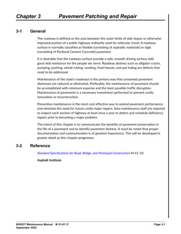
Roadway Pavement MarkingsWHITE LANE LINE PAVEMENT MARKINGS & WARRANTSWhite lane line pavement markings delineate traffic lanes with the same direction of travel.These markings should be installed on roadways with two or more adjacent traffic lanes inthe same direction of travel (unless required for reversible lanes). Lane line markingsshould also be used at congested locations with more traffic lanes having lane linemarkings than those without markings. These lane line markings will consist of a normalbroken white line - except where crossing the markings is allowed.Solid White Line: requires drivers to stay within the lane and marks the shoulderof the roadway.Broken White Line: motorists may change lanes if it is safe to do so.Dotted white line markings are used as lane lines to separate through lanes from adjacentlanes for any of the following cases:Deceleration or acceleration laneThrough lane that becomes a mandatory exit or turn laneAuxiliary lane (2 miles or less in length) between an entrance ramp and an exit rampAuxiliary lane (1 mile or less in length) between two adjacent intersectionsExit RampsA normal width dotted white lane line should be used for exit ramps with paralleldeceleration lanes from the upstream end of the full-width deceleration lane to thetheoretical gore* or to the end of a solid white lane line upstream from the theoretical gore(Figure 3B-8, Drawings A and C). A normal width dotted white line extension may also beinstalled in the taper area upstream from the full-width deceleration lane.*Theoretical gore: the tip of the triangular-shaped neutral area where the channelizing linefor the ramp separates from the channelizing line for the adjacent through lane.Copyright 2015Gregory J. Taylor, P.E.Page 18 of 64
Roadway Pavement MarkingsOn exit ramps with tapered deceleration lanes, a normal width dotted white line extensionmay be used from the theoretical gore through the taper area to the edge line at theupstream taper end (Figure 3B-8, Drawing B).Copyright 2015Gregory J. Taylor, P.E.Page 19 of 64
Roadway Pavement MarkingsEntrance RampsA normal width dotted white lane line should be used on entrance ramps with parallelacceleration lanes from the theoretical gore or from the downstream end of a solid whitelane line to at least one-half the distance from the theoretical gore to the downstream endCopyright 2015Gregory J. Taylor, P.E.Page 20 of 64
Roadway Pavement Markingsof the acceleration taper (Figure 3B-9, Drawing A). A normal width dotted white lineextension can also be installed from the downstream end of the dotted white lane line tothe downstream end of the acceleration taper.For entrance ramps with tapered acceleration lanes, a normal width dotted white lineextension may be used from the downstream end of the channelization marking adjacent tothe through lane to the downstream end of the acceleration taper (Figure 3B-9, Drawings Band C).Copyright 2015Gregory J. Taylor, P.E.Page 21 of 64
Roadway Pavement MarkingsCopyright 2015Gregory J. Taylor, P.E.Page 22 of 64
Roadway Pavement MarkingsUSES OF WIDE DOTTED WHITE LANE LINES In advance of freeway route splits with dedicated lanes Lane drop marking in advance intersection lane drops to distinguish a lane dropfrom an intersection through lane To separate a through lane that continues beyond an intersection from adjacentauxiliary lanes between two intersections Lane drop marking in advance of exit ramp lane drops to distinguish a lane dropfrom a normal exit ramp To separate a through lane that continues beyond an interchange from anadjacent auxiliary lane between an entrance ramp and an exit rampLane Drop MarkingsLane drop markings used in advance of exit ramps should start a minimum of 1/2 mile inadvance of the theoretical gore.Lane line markings should be used on multi-lane exit ramp approaches with optional exitlanes for through traffic. If the right-most exit lane is an added lane (i.e. paralleldeceleration lane), the marking should begin at the upstream end of the full-widthdeceleration lane.Lane drop markings used in advance of intersection lane drops should begin a distance thatis determined by engineering judgment as suitable to enable drivers (not making themandatory turn) to exit the lane being dropped before reaching the queue of waitingvehicles. This marking should start no closer than the most upstream sign associated withthe lane drop.Dotted white lane lines used for lane drops and lane lines separating through lanes fromauxiliary lanes consist of 3-foot line segments separated by 9-foot gaps.Normal or wide solid white lane line markings should be used where crossing lane linemarkings are discouraged,Wide solid lane line markings may be used at different locations for greater emphasis.Copyright 2015Gregory J. Taylor, P.E.Page 23 of 64
Roadway Pavement MarkingsSolid double white line markings should be used where crossing the lane line markings isprohibited.EDGE LINE PAVEMENT MARKINGSEdge line pavement markings delineate roadway edges. These are valuable as visualreferences during adverse weather and visibility conditions. Edge lines should not becontinued through intersections or major driveways.For divided highways, one-way streets, or ramps - normal solid yellow lines can be used todelineate the left-side of a roadway or to indicate restrictions left of these markings.Normal solid white lines can be used for delineating the right-hand edge of the roadway.Wide solid edge line markings can be used at locations with a need for greater emphasis.Warrants for Use of Edge LinesEdge line markings must be used on roadways with the following characteristics: FreewaysExpresswaysRural arterials**Minimum traveled way width of 20 feet with a minimum ADT of 6,000 vehicles per dayEdge lines are also recommended on the following roadways: Rural arterials and collectors (20-ft minimum traveled way and a minimum ADTof 3000 vehicles/day)Where engineering judgment indicates a needEdge line pavement markings can also be used on roads with or without center linemarkings.RAISED PAVEMENT MARKERS (RPM)Raised pavement markers can supplement or substitute for roadway pavement markings.These may be either retroreflective or non-retroreflective with prismatic cube-cornerreflectors used for necessary retroreflective properties.Copyright 2015Gregory J. Taylor, P.E.Page 24 of 64
Roadway Pavement MarkingsAdvantages of Raised Pavement Markers Increased visibility under adverse weather conditions Better durability than markings Tactile and audible warnings Use as transverse rumble stripsThe color of RPMs under both daylight and nighttime conditions needs to conform to thecolor of the marking for which they serve, supplement or substitute. Retroreflective orinternally illuminated raised pavement markers can be used in the roadway borderingcurbed approach ends or on top of raised medians and island curbs. These markers areavailable in mono-directional and bidirectional (capable of displaying the applicable colorfor each direction of travel). All internally illuminated markers must be steadily illuminatedand not flash when used.Non-retroreflective raised pavement markers should never be used alone as a substitutefor other types of pavement markings without supplemental retroreflective or internallyilluminated markers.Directional configurations should maximize correct information and minimize confusinginformation from visibility of markers that do not apply to the road user.The spacing of retroreflective RPMs should correspond with the pattern of broken lines(40-ft for normal rural roadways) for which the markers serve, supplement or substitute.Nonreflective markers for broken-line segments should be used in groups of three to five –depending on the normal lane marking length. For additional emphasis, retroreflectiveraised pavement markers may be spaced closer than described in the MUTCD if determinedby engineering judgment.The “Traffic Control Devices Handbook” contains further details pertaining to the spacing ofraised pavement markers for longitudinal markings.Disadvantages of RPMs High installation costs Susceptible to damage or removalRaised pavement markers must be protected from snowplow blades in locationssusceptible to snowy conditions. Snowplowable markers are encased in durable castingsdesigned to guide blades over the marker – while standard markers can be recessed belowthe roadway surface to prevent damage.Copyright 2015Gregory J. Taylor, P.E.Page 25 of 64
STOP & YIELD LINESRoadway Pavement MarkingsStop and yield lines are transverse pavement markings used to inform drivers where toshould stop or yield when approaching an intersection or mid-block crosswalk. Thesemarkings are typically white lines that are perpendicular to the travel path (stop lines,yield lines, crosswalks) as well as special markings (symbols, word markings,channelization markings, etc.).A stop line informs drivers where they are required to stop at an intersection orroundabout controlled by a stop sign or traffic light. These line markings should be 12 to 24inches wide. Stop and yield lines should be placed a minimum of 4 feet in advance of thenearest crosswalk at controlled intersections (except for yield lines at roundabouts or atmid block crosswalks). For locations without marked crosswalks, the stop line or yield lineshould be placed at the desired stopping or yield point, a minimum distance of 4 feet (witha maximum of 30 feet) from the nearest edge of the intersecting traveled way. Stop linelocations should allow sufficient sight distance to all other approaches for an intersection.However, stop lines should not be used where drivers are required to yield or onuncontrolled approaches where drivers are required to yield to pedestrians.For midblock signalized locations, stop lines should be placed a minimum distance of 40feet prior to the nearest signal indication.Yield lines (also called Shark’s Teeth or Give Way Line) inform drive
For this course, the Manual on Uniform Traffic Control Devices for Streets and Highways (MUTCD) 2009 Edition will serve as a referencefor the fundamental design principles of pavement markings. The MUTCD is recognized as the national standardfor all traffic control devices installed on any street,