Transcription
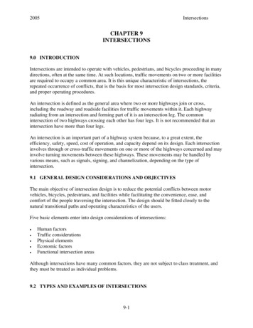
2005IntersectionsCHAPTER 9INTERSECTIONS9.0 INTRODUCTIONIntersections are intended to operate with vehicles, pedestrians, and bicycles proceeding in manydirections, often at the same time. At such locations, traffic movements on two or more facilitiesare required to occupy a common area. It is this unique characteristic of intersections, therepeated occurrence of conflicts, that is the basis for most intersection design standards, criteria,and proper operating procedures.An intersection is defined as the general area where two or more highways join or cross,including the roadway and roadside facilities for traffic movements within it. Each highwayradiating from an intersection and forming part of it is an intersection leg. The commonintersection of two highways crossing each other has four legs. It is not recommended that anintersection have more than four legs.An intersection is an important part of a highway system because, to a great extent, theefficiency, safety, speed, cost of operation, and capacity depend on its design. Each intersectioninvolves through or cross-traffic movements on one or more of the highways concerned and mayinvolve turning movements between these highways. These movements may be handled byvarious means, such as signals, signing, and channelization, depending on the type ofintersection.9.1 GENERAL DESIGN CONSIDERATIONS AND OBJECTIVESThe main objective of intersection design is to reduce the potential conflicts between motorvehicles, bicycles, pedestrians, and facilities while facilitating the convenience, ease, andcomfort of the people traversing the intersection. The design should be fitted closely to thenatural transitional paths and operating characteristics of the users.Five basic elements enter into design considerations of intersections: Human factorsTraffic considerationsPhysical elementsEconomic factorsFunctional intersection areasAlthough intersections have many common factors, they are not subject to class treatment, andthey must be treated as individual problems.9.2 TYPES AND EXAMPLES OF INTERSECTIONS9-1
Intersections20059.2.1 General ConsiderationsThe basic types of at-grade intersections are the T-intersection (with multiple variations ofangular approach), the four-leg intersection, the multi-leg intersections and roundabouts (seeChapter 19 and the FHWA Roundabout Guide). In each particular case, the type is determinedprimarily by the number of intersecting legs, the topography, the traffic pattern, and the desiredtype of operation.A basic intersection type can vary greatly in scope, shape, and degree of channelization. Oncethe type of intersection is established, the design controls and criteria covered in Chapter 2 andthe elements of intersection design given in Chapter 3 as well as in this chapter must be appliedto arrive at a suitable geometric plan.Each type of intersection is discussed separately in Chapter 9 of the PGDHS (1), and likelyvariations of each are demonstrated. It is not practical to discuss all possible variations, but thetypes demonstrated are sufficient to cover the general application of at-grade intersection design.Many other variations of types and treatment may be found in the NCHRP Report 279 (2), whichshows examples in detail that are not included in this Guide.9.3 CAPACITY ANALYSISCapacity and level of service analysis is one of the most important considerations in the designof intersections. This subject is discussed at length in Chapter 2 of the PGDHS (1) and isdiscussed throughout this chapter as it relates to the various elements of intersection design.Optimum capacities can be obtained when at-grade intersections include auxiliary lanes, properuse of channelization, and traffic control devices. For more complete coverage of capacity ofintersections, including procedures for making capacity computations, refer to Chapter 6 of theHighway Capacity Manual (3).9.4 ALIGNMENT AND PROFILE9.4.1 General ConsiderationsHorizontal and vertical alignment and cross-sectional features affect driver and/or vehiclebehavior at and on the approach to the intersection, and therefore are important designconsiderations. The horizontal and vertical alignment of the intersecting roads should permitusers to readily discern and perform the maneuvers necessary to pass through the intersectionssafely and with a minimum of interference by other users.As a rule, alignment and grade are subject to greater restriction at or near intersecting roads thanon the open road. Their combination at or near the intersection must produce traffic lanes that areclearly visible to the operators at all times and plainly understandable for any desired direction oftravel, free from unexpected hazards, and consistent with the portions of the highway justtraveled.9-2
2005Intersections9.4.2 AlignmentBoth individual vehicle operations and the nature of vehicle conflicts are affected by the angle ofintersection. Roads intersecting at acute angles require extensive turning roadway areas and tendto restrict visibility, particularly for drivers of trucks. When a truck turns on an obtuse angle, thedriver has blind areas on the right of the vehicle. Acute-angle intersections increase the exposuretime of the vehicles crossing the main traffic flow and may increase the accident potential.Angles of 75 to 90 degrees are generally considered desirable. Although not desirable, a 60degree angle is considered acceptable. New intersections should not include skewed angles lessthan 60 degrees without special design and control features to mitigate the effects of the skew.See Exhibit 9-69 in the PGDHS (1). These may include more positive traffic control (all stop,traffic signals) and/or geometric improvements such as greater corner sight distance.Geometric counter measures, although expensive, are generally the best solution in designingskewed-angle intersections. Reconstruction should reflect traffic patterns at the intersection aswell as constraints such as available right of way. The practice of realigning roads intersecting atacute angles in the manner shown in Chapter 9 of the PGDHS (1) has proven to be beneficial.Special care should be taken in designing intersections near horizontal curves. The driving taskof tracking the curve takes up much of the driver's focus, leaving less attention for conflictresolution.9.4.3 ProfileIn general, grades for intersecting roads should be as flat as possible to provide for storageplatforms and sight distance. Approach grades greater than 6 percent on low-speed highwaysshould be avoided. For high-speed highways, grades greater than 3 percent should be avoided.Most vehicle operators are unable to judge the increase or decrease in stopping or acceleratingdue to steep grades. Their normal deductions and reactions thus may be in error at a critical time.Therefore, on grades steeper than 3 percent, the grade adjustment factors need to be applied toother design elements to produce conditions equivalent to those on level highways.The effect of grade on acceleration can be expressed as a factor as shown in Table 10-5.The profile gradelines and cross sections on the intersection legs should be adjusted for adistance back from the intersection, generally 20 feet, to provide a smooth junction and properdrainage. Normally, the gradeline of the major highway should be carried through theintersection, and that of the crossroad should be adjusted to it.Changes from one cross slope to another should be gradual. Intersections with a minor roadcrossing a multilane divided highway with a narrow median and superelevated curve should beavoided whenever possible because of the difficulty in adjusting grades to provide a suitablecrossing.9.5 INTERSECTION CURVES9-3
Intersections20059.5.1 Widths for Turning Roadways at IntersectionsThe pavement and roadway widths of turning roadways at intersections are governed by thevolumes of turning traffic and the types of vehicles to be accommodated and may be designedfor one-way or two-way operation depending on the geometric pattern of the intersection. Widthsdetermined for turning roadways are also applied on all roadways within an intersection. Theturning radii and the pavement cross slopes are functions of design speed and type of vehicles.Pavement widths for turning roadways are classified as shown in Table 9-1 below.Radiuson InnerEdge ofPavement(ft)5075100150200300400500TangentCase IICase ICase IIIOne-Lane, One-WayTwo-Lane Operation – EitherOne-Lane, One-WayOperation – With Provision forOperation – No Provision forOne-Way or Two-WayPassing a Stalled VehiclePassing a Stalled VehiclePavement Width (Feet) for Design Traffic 5171921252728121414171820242626Width modification regarding edge neNoneNoneCurbVerticalcurb1 SideAdd 1 footNoneAdd 1 foot2 SidesAdd 2 feetAdd 1 footAdd 2 feetStabilizedLane width for conditions B andDeduct shoulder width;Deduct 2 feet where shoulder isshoulder,C may be reduced to 12 feetminimum pavement width aswhere shoulder is 4 feet or4 feet or wider.one orunder Case I.both sideswider.A Predominantly P vehicles, but some consideration for SU trucksB Sufficient SU vehicles to govern design, but some consideration for semi trailer combination trucksC Sufficient bus and combination-trucks to govern designTable 9-1 [Exhibit 3-51(1)] Design Widths of Pavements for Turning Roadways9.5.1.2 Widths Outside Traveled WayThe roadway width for a turning roadway, as distinct from pavement width, includes theshoulders or equivalent lateral clearance outside the edges of pavement.Table 9-2 (below) is a summary of the range of design values for the described general turningroadway conditions. On roadways without curbs or those with sloping curbs, the adjacent9-4
2005Intersectionsshoulder should be of the same type and section as that on the approach highway. The widthsshown are for usable shoulders. Where roadside barriers are provided, the width indicated shouldbe measured to the face of the barrier, and the graded width should be about 2 feet greater.Turning movements should be checked with modeling software.Turning RoadwayConditionShoulder Width or Lateral Clearance Outside ofTraveled Way Edge (feet)LeftRightShort length, usually within2 to 42 to 4channelized intersectionIntermediate to long length,4 to 106 to 12or in cut or on fillNote: All dimensions should be increased where necessary for sight distance.Table 9-2 [Exhibit 3-52 (1)] Range of Usable Shoulder Widths or Equivalent LateralClearances Outside Turning Roadways, Not on Structure9.5.2 Minimum Designs for Sharpest TurnsAfter the lane width has been determined, site conditions along with traffic and islandrequirements will govern the curve selection. Generally, a three-centered curve is used tominimize the paved area and right of way requirements. The curve should be suitable for theanticipated truck traffic with the design for the commercial vehicle (SU) considered the desirableminimum.Curbs along the edges of pavements of sharp intersection curves result in some restriction ofvehicles making the turn. A design vehicle making its minimum turn will need to be maneuveredcarefully to avoid scraping or jumping the curb. For this reason, when curbs are used, it isdesirable to use somewhat flatter curves than those in minimum edge-of-pavement designs.In the design of the edge of the pavement for the minimum path of a given design vehicle [seeExhibits 9-21 through 9-28 of the PGDHS (1)], it is assumed that the vehicle is properlypositioned within the traffic lane at the beginning and end of the turn, i.e., 2 feet from the edge ofpavement on the tangents approaching and leaving the intersection curve. Curve designs for edgeof pavement conforming to this assumption, for passenger vehicles, single-unit trucks and buses,and semitrailer combinations are shown in Chapter 9 of the PGDHS (1). The paths indicated,which are slightly greater than the minimum paths of nearly all vehicles in each class, are theminimums attainable at speeds less than 10 mph. In each case, these widths must be increased toaddress turning movements of vehicles over 10 mph operating speed. The wheel path should be 2feet or more away from the edge of pavement throughout most of the turn, and at no point lessthan 9 inches. Although not shown separately in the figures in the PGDHS (1), these edgedesigns also apply for left turn layouts such as a left turn to leave a divided highway at a verylow speed. The designer should allow for an occasional large truck to turn by swinging wide andencroaching on other traffic lanes without disrupting traffic significantly. The designer should9-5
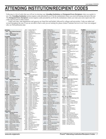
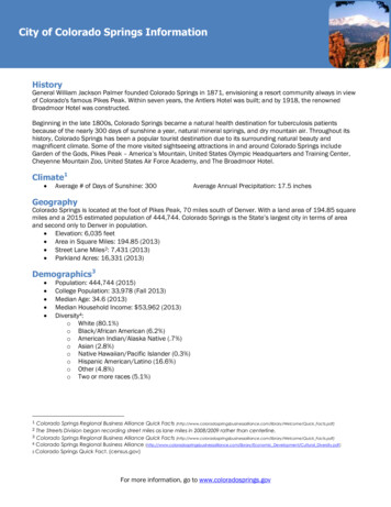
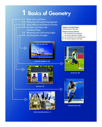
Intersections2005analyze the likely paths and encroachments that will result when a turn is made by a largevehicle.The design should be modified where alignment conditions such as curvature prior to or at theend of the turn provide the assumed positioning. Superimposing the appropriate design-vehicleturning template is the most expeditious way to customize a design for special conditions.Figures and data for three-centered curves (symmetrical and asymmetrical) are shown in Figures9-1A, 9-1B, and 9-2, below, and Exhibit 9-20 in the PGDHS (1).9-6
2005IntersectionsFigure 9-1A Three-Centered Compound Curve (Symmetrical)9-7
Intersections2005Figure 9-1B Three-Centered Compound Curve (Symmetrical) Greater than 180 9-8
2005IntersectionsFigure 9-2 Three-Centered Compound Curve (Asymmetrical)9-9
Intersections20059.5.2.1 Design VehiclesA description of the design vehicles used for intersection design is given in Chapter 2. For athorough discussion and dimensions of the design vehicles, see Chapter 2 of the PGDHS (1).Select a design vehicle that is the largest vehicle that normally uses the intersection. The primaryuse of the design vehicle is to determine turning radius requirements for each leg of theintersection. It is possible for each leg to have a different design vehicle. Table 9-3 shows theminimum design vehicles. As justification to use a smaller vehicle, include a traffic analysisshowing that the proposed vehicle is appropriate.Intersection TypeDesign VehicleJunction of Major Truck RoutesWB-67Junction of State HighwaysWB-50Ramp TerminalsWB-50Other tialSU(1)(2)(1)To accommodate pedestrians, the P vehicle may beused as the design vehicle if justification with a trafficanalysis is documented.(2)When the intersection is on a transit or school busroute, use the BUS design vehicle as a minimum.Table 9-3 (WSDOT) Intersection Design VehicleTo minimize the disruption to other traffic, design the intersection to allow the design vehicles tomake each turning movement without encroaching on curbs, opposing lanes, or same-directionlanes at the entrance leg.Design each turning movement so the largest vehicle that is anticipated to regularly use theintersection can make the turn without leaving the paved shoulders or encroaching on a sidewalk.Use the WB-67 as the largest vehicle at all State highway to State highway junctions.9.5.2.2 Effect of Curb Radii on Turning PathsThe widths for various angles of intersecting streets occupied by turning vehicles are shown inExhibit 9-31 and 9-32 of the PGDHS (1). When the angles increase, the streets must be very9-10
2005Intersectionswide or a very large curb radius must be used. For this reason, three-centered curves arepreferred for this type of situation.Corner radii at intersections on arterial streets should satisfy the requirements of the drivers usingthem to the extent practical. The design should consider the amount of right of way available, theangle of intersection, number of pedestrians, width and number of lanes on the intersectingstreets, and amount of speed reductions.Consider the following: Radii of 15 to 25 feet are adequate for passenger vehicles. These radii may be provided atminor cross streets where there is little occasion for trucks to turn or at minor intersectionswhere there are parking lanes. Where the street has sufficient capacity to retain the curb laneas a parking lane for the foreseeable future, parking should be restricted for appropriatedistances from the crossing. Radii of 25 feet or more at minor cross streets should be provided on new construction andon reconstruction where space permits. Radii of 30 feet or more at major cross streets should be provided where feasible so that anoccasional truck can turn without too much encroachment. Radii of 40 feet or more, and preferably three-centered compound curves or simple curveswith tapers to fit the paths of appropriate design vehicles, should be provided where largetruck combinations and buses turn frequently. Longer radii are also desirable where speedreductions would cause problems. Curb radii should be coordinated with crosswalk distances or special designs to makecrosswalks safe for all pedestrians.9.6 TYPES OF TURNING ROADWAYS9.6.1 Oblique-Angle TurnsThe designs given in Exhibit 9-31 of the PGDHS (1) relating to minimum edge-of-pavementdesigns for turns at intersections are those suggested to fit the sharpest turns of the differentdesign vehicles at oblique-angle intersections. For angles of turn less than 90 degrees, trucks alsocan turn on an inner edge of pavement designed for passenger vehicles with even lessencroachment than that for the 90-degree turns. For turning angles of more than 90 degrees, theminimum design must be adjusted to ensure that all turning trucks remain within two lanes ofpavement on each highway.9.6.2 Development of Superelevation at Turning Roadway TerminalsSuperelevation commensurate with curvature and speed seldom is practical at terminals where:9-11
Intersections2005 A flat intersection curve results in little more than a widening of the through trafficpavement. It is desirable to retain the cross slope of the through pavement. There is a practical limit to the difference between the cross slope on the through pavementand that on the intersection curve.9.6.3 General ProcedureThe method of developing superelevation at turning roadway terminals is illustrated in Exhibits9-45 through 9-49 of the PGDHS (1).9.7 ISLANDS9.7.1 General CharacteristicsAn at-grade intersection in which traffic is directed into definite paths by islands is termed achannelized intersection.An island is a defined area between traffic lanes for control of vehicle movements. Within anintersection, a median or an outer separation is considered an island. This definition makesevident that an island is no single physical type. It may range from an area delineated by a curbto a pavement area marked by paint.Islands generally are included in intersection design (channelization) for one or more of thefollowing purposes: Separation of conflictsControl of angle of conflictReduction in excessive pavement areasRegulation of traffic and indication of proper use of intersectionArrangements to favor a predominant turning movementProtection of pedestrians (ADA requirements should be considered.)Protection and storage of turning and crossing vehiclesLocation of traffic control devicesAccess controlIslands generally are either elongated or triangular in shape and are situated in areas normallyunused as vehicle paths. Their sizes and shapes vary materially from one intersection to another.Further variations occur at multiple and acute angle intersections. The dimensions depend on theparticular intersection design. Islands should be located and designed to offer little hazard tovehicles, be relatively inexpensive to build and maintain, and occupy a minimum of roadwayspace, yet be commanding enough that motorists will not drive over them.9-12
2005IntersectionsWhere various intersections are involved in a given project and the warrants are sufficientlysimilar, in order to enhance driver expectancy, it is desirable to provide a common geometricdesign for each intersection.Painted, flush medians and islands may be preferred to the curbed type under certain conditions,including the following: In lightly developed areasAt intersections where approach speeds are relatively highWhere there is little pedestrian trafficWhere fixed-source lighting is not providedWhere signals, signs, or lighting standards are not needed on the median or islandPainted islands may also be placed at the pavement edge. At some intersections, both curbed andpainted islands may be desirable. All pavement markings should be reflectorized. The use ofthermoplastic striping and other forms of long-life markings also may be desirable. For thevarious types and shapes of islands, see Exhibit 9-35 of the PGDHS (1).9.7.2 Island Size and DesignationIslands should be sufficiently large to command attention. The smallest curbed island thatnormally should be considered is one that has an area of approximately 50-square feet for urbanand 75-square feet for rural intersections. However, 100-square feet are preferable for both.Accordingly, triangular islands should not be less than about 12 feet, and preferably 15 feet, on aside after rounding of corners. Elongated or divisional islands should be not less than 4-feet wideand 20 to 25 feet long.In general, introducing curbed divisional islands at isolated intersections on high-speed highwaysis undesirable unless special attention is directed to providing high visibility for the islands.Curbed divisional islands introduced at isolated intersections on high-speed highways should beat least 100 feet and preferably several hundred feet in length. Details of triangular curbedislands and their size designation are shown in Chapter 9 of the PGDHS (1).9.7.3 DelineationIslands should be delineated or outlined by a variety of treatments, depending on their size,location, and function. The type of area in which the intersection is located, rural versus urban,also governs the design. In a physical sense, islands can be divided into three groups: Raised islands outlined by curbs. Islands delineated by pavement markings, buttons, or raised (jiggle) bars placed on all pavedareas.9-13
Intersections 2005Non-paved areas formed by the pavement edges, possibly supplemented by delineators onposts or other guideposts, or a mounded earth treatment beyond and adjacent to the pavementedges.Delineation of small-curbed islands is effected primarily by curbs. Large curbed islands may besufficiently delineated by color and texture contrast of vegetative cover, mounded earth, shrubs,guard posts, signs, or any combination of these. In rural areas, island curbs should nearly alwaysbe a sloping type, except where there is a definite need for a vertical curb, as at structures orpedestrian crossings. In special cases, vertical curbs are suitable, commonly of heights not morethan 6 inches. Vertical or sloping curb could be appropriate in urban areas, depending on thecondition. High-visibility curbs are advantageous at critical locations or on islands and roadwayforks approached by high-speed traffic.Curbed islands are sometimes difficult to see at night because of the glare from oncomingheadlights or from distant luminaires or roadside businesses. Accordingly, where curbed islandsare used, the intersection should have fixed-source lighting or appropriate delineation.Delineation and warning devices are especially pertinent at approach ends of median curbedislands, which are usually in a direct line with approaching traffic. In rural areas, the approachshould consist of a gradually widening center stripe. Although not as frequently obtainable, thisapproach should be strived for in urban areas also. Preferably, it should gradually change to araised marking of color and texture contrasting with that of the traffic lanes or to jiggle bars thatmay be crossed readily even at considerable speed. This section should be as long as practicable.9.7.4 Approach TreatmentThe outline of a curbed island is determined by the edge of through traffic lanes and turningroadways, with lateral clearance to the curbed island sides. The points at the intersections of thecurbed island are rounded or beveled for visibility and construction simplicity. The amount that acurbed island is offset from the through traffic lane is influenced by the type of edge treatmentand other factors such as island contrast, length of taper or auxiliary pavement preceding thecurbed island, and traffic speed. Island curbs are introduced rather suddenly and should be offsetfrom the edge of through traffic lanes even if they are sloping. A sloping curb at an island neednot be offset from the edge of a turning roadway, except to reduce its vulnerability. Considerplowable end treatments. Vertical curbs should be offset from the edges of through and turningroadway pavements.See Exhibit 9-41 in the PGDHS (1).9.7.5 Right-Angle Turns With Corner IslandsThe turning roadway pavement should be wide enough to permit the outer and the inner wheeltracks of a selected vehicle to be within the edges of the pavement by about 2 feet on each side.Generally, the turning roadway pavement width should not be less than 14 feet. For designs ofturning roadways of 90 degrees with minimum corner islands see Exhibits 9-37 through 9-41 ofthe PGDHS (1).9-14
2005Intersections9.7.6 Oblique-Angle Turns With Corner IslandsMinimum design dimensions for oblique-angle turns, determined on a basis similar to that forright-angle turns, are given in Table 9-4. Curve design for the inner edge of pavement, turningroadway pavement width, and the approximate island size are indicated for the three chosendesign classifications described at the bottom of the table. For a particular intersection, thedesigner may choose from the designs shown in accordance with the size of vehicles, the volumeof traffic anticipated, and the physical controls at the site.Three-Centered CurveAngle nRadii (ft)Offset (ft)Width ofLane (ft)ApproximateIsland Size(sq 100-30-1006.0301170C160-35-1607.1381720A - Primarily passenger vehicles: permits occasional design single-unit truck to turn with restrictedclearances.B - Provides adequately for SU: permits occasional WB-50 to turn with slight encroachment onadjacent traffic lanes.C - Provides fully for WB-50.Asymmetric three-centered compound curves and straight tapers with a simple curve can also be usedwithout significantly altering the width of roadway or corner island size.Table 9-4 [Exhibit 9-42(1)] Typical Designs for Turning Roadways9-15
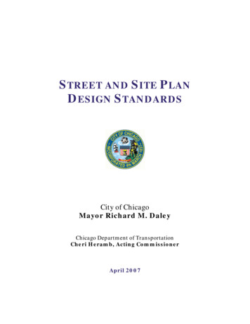
Intersections2005In Table 9-4, design values are not given for angles of turn less than 75 degrees. Turningroadways for flat-angle turns involve relatively large radii and are not considered in theminimum class. Such arrangements require individual design to fit site controls and trafficconditions. For angles of turn between 75 and 120 degrees, the designs are governed by aminimum island, providing for turns on more than minimum turning radii. For angles of 120degrees or more, the sharpest turning paths of the selected vehicles, and arrangements of curveson the inner edge of traveled way to fit these paths, generally control the design. The resultingisland size is greater than the minimum. The size of the islands for the large turning angles inTable 9-4 is indicative of the otherwise unused and uncontrolled areas of traveled way that areeliminated by the use of islands.9.8 INTERSECTION SIGHT DISTANCE9.8.1 General ConsiderationsConflicts between vehicles at intersections are resolved by providing appropriate sight distancesand traffic controls. The avoidance of accidents and the efficiency of the traffic operations stilldepend on the judgment, capabilities, and response of the individual driver. The sight distanceconsidered safe is directly related to vehicle speeds and to the resultant distances traversedduring perception, reaction time, and braking.Each vehicle approaching an intersection must have an unobstructed sight distance along all legsof the cross road and across its included corners for a distance sufficient to allow the drivers tosee each other in time to prevent a collision.Each driver can either: AccelerateSlow downStopAfter a vehicle has stopped at an intersection, the driver must be able to make a safe departurethrough the intersection area. Figures 9-3A and B indicate these maneuvers as well as the sightdistances that must be provided for vehicles approaching on the major highway from eitherdirection. Distance “b” is the length of roadway traveled by the respective vehicle on the majorroadway during the time required for the stopped vehicle to depart from its stopped position andeither cross the intersection or to turn onto the major roadway.9-16
2005IntersectionsFigure 9-3A Sight Distance at Intersections, Minimum Sight Triangle9-17
Intersections2005Figure 9-3B Sight Distance at Intersections, Minimum Sight Triangle9-18
2005Intersections9.8.2 Intersection ControlThe recommended dimensions of the sight triangles vary with the type of traffic control used atan intersection because different types of control impose different legal constraints on driversand, therefore, result in different driver behavior. Procedures to determine sight distances atintersections are presented in Chapter 9 of the PGDHS (1) for each of the Cases below:Case A --Intersections with no control (not used on State highways)Case B -- Intersections with stop control on the minor roadCase B1 – Left turn from the minor roadCase B2 – Right turn from the min
9.5.1.2 Widths Outside Traveled Way The roadway width for a turning roadway, as distinct from pavement width, includes the shoulders or equivalent lateral clearance outside the edges of pavement. Table 9-2 (below) is a summary of the range of design values for the described general turning roadway conditions.