Transcription
WWFTE 2010IBIS-AMI GenerationRuss KramerIC Design Expert TechnicalConsultant
AgendaPSU SI Conference2015 Background AMI Model Generation Barriers Automated AMI Model-generation flow Benefits of Automated AMI flow IBIS-AMI model ADS PAM 4 applications at 28 and 56 GB/s (DesignCon 2015)Page 2
Why You Can’t Use SPICE For Multigigabit/s SERDESSub-gigabit/s yesterday Circuitry is too complex 10’s k transistors in the Design space istoo big- Tx settings Channel design Rxsetting Thousands of simulations- ic blockMultigigabit/s todayAltera’s Adaptive EqualizerRGEN – Referenceedge generator.LPFHPF.RECT – Rectifiers andintegratorsComparatorsDigital controls andfilterD2A – Digital to analogconverterGo to www.youtube.com and search for “ADCE” to see videoSource: Altera/Agilent joint webcastPSU SI Conference2015Page 3
IBIS: Input/output Buffer InformationSpecification IBIS Open Forum is an organization developing industrystandards- http://www.eda-stds.org/ibis/ IBIS 5.0 ratified August 2008 adds an AlgorithmicModeling Interface (AMI) flow as an alternate to thetraditional flow Keysight supports IBIS:- Two Keysight engineers serve on IBIS Open Forum- SystemVue AMI Modeling Kit for AMI model builders(typically IC vendors)- Channel Simulator in ADS Transient Convolution formodel users (typically OEMs)PSU SI Conference2015Page 4
What Does IBIS AMI Flow Offer?PSU SI Conference2015Page 5– Portability & IP Protection: One IC model runs in manyEDA tools, without the need for non-portable, proprietaryencryption keys– Interoperability: IC Vendor A IC Vendor B– Performance: Ultralow BER contours in seconds not days– Flexibility: Simulator has statistical and bit-by-bit (“time domain”)modes Models can have LTI and/or NLTV algorithms IC vendor can expose arbitrary model-parametersOptimization:Simulator can sweepmodel-specificparameter quickly
OK, But What’s the Catch? Must use a channel simulator, not transient simulator (SPICE)- although channel simulator can call other simulators(transient, EM) for generalized channel characterization In version 5.0, channel must be linear and time invariant (LTI)- although this restriction is being lifted in a future version toaccommodate re-drivers, re-timers etc. (e.g. BIRD 133) Non-linear time varying Tx and Rx must be expressed ascompiled C code with a specific API *.dll or *.so is OS-specific Fixed topology- although channel canbe made of any arbitrarylumped or distributedelements (if LTI) Patching machine code intosimulator, not parsing lang.PSU SI Conference2015Page 6
What Do the Two New Files Represent?XTalk1PRBSTXJitter EQAnalog driversand packageJitterChannelPRBSXTalkNPRBS EQAnalog driversand packageAnalog driversand package EQ/CDRReceivedSignalJitter RXJitterEQ*.ami and *.dll filesAnalog driversand package*.ibs filesChannel modelin ADS lumpedand distributedcomponents*.ibs files Rx *.ami and *.dll filesPSU SI Conference2015Page 7
AMI Model Generation Barriers#1 AMI modeling barrierModel Generation TimeAMI Modeling suppose to Speed-up System Design Cycle,BUT, Model-generation takes Significant Time & Resources .System Vendors have to wait a LONGtime before accurate AMI models becomeavailableNote: Vendors with NO experience in AMI modeling are spending 6-12 months tocome up with first-generation modelsModels come very late in Design Cycle used only for Validation, NOT DesignPSU SI Conference2015Page 8
Why AMI-model generation takes so long?Typical Signal Integrity Engineers are NOT programmers .they are having “Nightmares” in tryingto develop AMI models Cryptic Matlab/C code passed from System-Architectures AMI Modeler (if lucky) Challenge to Convert Algorithm design Code AMI format0 monthsNightmare BeginsAMI 101, Decipher Code4 months8 monthsEarly Model prototypesFirst-model to Customer12 monthsPSU SI Conference2015Page 9
Typical AMI model generation flow JanFebMarAprMayJunJulAugSepOctNovDecMatlab/C ModelCompile C codeC Code - AMI (.dll, .ami)Channel Simulator ValidationPSU SI Conference2015Page 10
Automated AMI model generation flow JanFebMarAprMayJunJulAugSepOctNovDecMatlab/C ModelLibrary of CommonBuilding Blocks-FIR/IIR-FFE/DFE-CDR-S-block-Peaking, VGA etc.Compile C codeAutomatic C Code GenerationC Code - AMI (.dll, .ami)Automatic AMI GenerationChannel Simulator ValidationAutomated AMI FlowPSU SI Conference2015Page 11
ESL flow for Automated AMI ModelingElectronic System Level (ESL) design and verification is an emerging electronic designmethodology that focuses on the higher abstraction level concerns first and foremost.ESL flow facilitates utilization of appropriate abstractions in order to increasecomprehension about a system, and to enhance the probability of a successfulimplementation of functionality in a cost-effective mannerHere is an Example of SerDes modeling in SystemVue:Generate square bitwave, includingmodeling impairmentsAMI TXTyco ChannelCTLE Output11010clockSDataInputO utputinputoutputJitterGeneratorAMI Tx 6P1 {JitterGenerator@Data Flow Models}VHigh 1VVLow -1VEdgeTime 0.0sSamplesPerUI 16InitialState 0DCD 0psPJ Amplitude 0psPJ Frequency 0GHzRJ 0psData3 {AMI Tx 6}inputAMI CT LE RxoutputbitB1 {PRBS@Data Flow Models}BitRate 10.31e 9Hz [BitRate]S2 {SData@Data Flow Models}DataSource DatasetDatasetName 'Tyco Channel Diff.s2pData2 {AMI CTLE Rx}SamplesPerBit 16 [SamplesPerBit]DFETaps 0;0;0;0 [[0 0 0 0]]Alpha 0.0001SampleInterval 6.061e-12 [1/(BitRate*SamplesPerBit)]PSU SI Conference2015Page 12
Example6.0 Gb/s (SATA 3.0)DCD 0ps06.25 GHz SerDes1FlexDCA1A Transmitted Signal1B Received Signal after Channel2A Received Signal after CTLE2B Received Signal after CTLE & DFEPJ Amplitude 0ps010e-12PJ Frequency 0GHz110RJ 0psm cbbI nputsFl ex DCA Sin k01CTLE & DFEAMI RxGenerate square bitwave, includingmodeling impairmentsAMI TXTyco Channel123CTLE O ut put11010SDataI nputO ut putinputout putJ i tterGe n eratorAMI Tx 6P1 {JitterGenerator@Data Flow Models}VHigh 1VVLow -1VEdgeTime 0.0sS amplesPerUI 16InitialState 0DCD 0psPJ Amplitude 0psPJ Frequency 0GHzRJ 0psData3 {A MI Tx 6}N1 {FlexDCA Sink@Data Flow Models}NumberOfInputs 1S1 {Sink@Data Flow Models}StartStopOption SamplesclockinputAM I CTL E Rxout putbitB1 {PRBS@Data Flow Models}BitRate 6.25e 9Hz [BitRate]S2 {SData@Data Flow Models}DataSource DatasetDatasetName 'Tyco Channel Diff.s2pData2 {AMI CTLE Rx}SamplesP erBit 16 [SamplesPerB ]itDFETaps 0;0;0;0 [[0 0 0 0]]Alpha 0.0001SampleInterval 10e-12 [1/(BitRate* SamplesPerB it)]123RxBits {Sink@Data Flow Models}StartStopOption SamplesPSU SI Conference2015Page 13
TX Modeling6.0 Gb/s (SATA 3.0)Step-1: Architecture Design of Tx with built-in modelsinputoutputBlindFFES1 {TimeResponseFIR@Data Flow Models}ResponseType Step ResponseResponse Real Array (46x1)ResponseTimeStamps Real Array (46x1)TimeStep 1e-12 [sample interval]FIR filterG1 {Gain@Data Flow Models}Gain 1 [Gain]B2 {BlindFFE@Data Flow Models}Coefficients 0;1;0 [Taps]SamplesPerBit 16 [SamplesPerBit]3-tapFFENote: The BlindFFE in the example has 3 implementations: built in C model, M code, and compiled M code. Use the manage model list toselect the different ones. The example workspace has instructions to load the compiled M code model. See the slides for SV2: C ModelBuilder more information on the compile M code model.PSU SI Conference2015Page 14
TimeReponseFIR Filter enables importingHSpice or measured dataChallenges:1. Typical Simulation and Measured Data is not equally time-steppedSampling Rate determines Simulation AccuracyLow Sampling RateHigh Sampling RateFIR model should support“Arbitrary” Sampling RatePSU SI Conference2015Page 15
ESL flow: TX Modeling Example (2)Step-2: Customize IP - Bring in Matlab, mathlang, or C CodeFine-tune and Customizemodels with Math Langand/or C codePSU SI Conference2015Page 16
RX Modeling6.0 Gb/s (SATA 3.0)Step-3: Architecture Design of Rx with built-in modelsclockCTLEAMI RxinputSinputclockbitCDRC1 {CDR@Data Flow Models}SamplesPerBit 16 ta1 {CTLE Rx}SampleInterval 1 [SampleInterval]B2 {BlindDFE@Data Flow Models}Coefficients 1;0;0 [DFETaps]Alpha 0.01 [Alpha]CTLE OutputS-domainfilter3-tapDFENote: The CTLE design used here is the one detailed in the EDN article: “Continuous-time equalizers improve high-speed serial links”.The CDR in this implementation is simple and provides a useful C model template to import a custom C CDR code. A second Rxdesign is provided that implements a more realistic CDR (use manage models list on top-level to select).PSU SI Conference2015Page 17
Results – Displayed in Agilent FlexDCA6.0 Gb/s (SATA 3.0)Step-4: Verify design using Agilent FlexDCATX OutputAfter CTLE EQAfter ChannelAfter CTLE DFE EQNote: FlexDCA Eye and Oscilloscope Modes are included as part of base SystemVue product! Separate installation is required.PSU SI Conference2015Page 18
One-click AMI Code-GenerationinputStep-5: Configure AMI models and generate models with oneclick.outputAMI Tx 6Data3 {AMI Tx 6}Define Reserved and Model Specific Parameters - Automatically configure appropriate AMI wrapperOne-click AMICode-generationPSU SI Conference2015Page 19
Automatically generated .ami and Visual-StudioprojectThe visual studio project automaticallycreated - One click to create .dllPSU SI Conference2015Page 20
Benefits of ESL Design FlowAutomated AMI-Model Generation1. Complete “Automation” of Code-generation and Model Compilationa task that routinely takes months because of its complexity2. Basic building blocks that can used to start model developmentFIR/IIR filters, FFE, DFE, CDR etc.3. Easily customize models to include custom IPCustom C and MatlabPSU SI Conference2015Page 21
Validating AMI-Model in ADS ChannelSimulator1. Verify generated AMI models in ADS.2. Generated AMI models support all IBIS-5.0 compliant channel simulators.2.PSU SI Conference2015Page 22
Keysight Education ForumSimulation and Characterization of PAM-4signals in 28G and 56G Designs using IBISAMI models
Simulation and Characterization ofPAM-4 signals in 28G and 56GDesigns using IBIS-AMI models– Overview: Pulse Amplitude Module (PAM-4)– PAM-4 End-to-End Link Simulation– PAM-4 TX Characterization– Summary– Q&APSU SI Conference2015Page 24
NRZ (Non-Return-to-Zero) vs. PAM (Pulse Amplitude Modulation)NRZ (PAM-2)PAM-4 2 amplitude levels 1 bit of information in every symbol 4 amplitude levels 2 bits of information in every symbol 2x throughput for the same Baud rate 28 GBaud PAM-4 56 Gb/s Lower SNR, more susceptible to noise More complex TX/RX design, higher costPSU SI Conference2015Page 25
Status of Standards using PAM-4 Implemented IEEE 802.3bj clause 94 (25.78 Gb/s as 13.6 GBaud PAM-4 in 1m backplane) Low adoption rate – limited advantages over clause 93 – 25.78 G NRZ Under development/discussion OIF CEI 4.0 (56G-VSR, MR, LR) 28 GBaud using PAM-4 Basis for other standards – Ethernet, Fiber Channel, Infiniband, .Note - 56 GBaud NRZ for Ultra Short Reach applications IEEE 802.3bs PAM-4 Proposals being discussed to support 400 GbE Chip-to-Chip (c2c)and Chip-to-Module (c2m) PAM-4 to work on existing CAUI-4 (100G) infrastructures 64G Fibre ChannelPSU SI Conference2015Page 26
Typical PAM-4 Communication SystemsTransmitter, Channel, ReceiverChip(e.g. VSR)Channele.g. CEI-56G VSRChip-to-ChipChip(e.g. VSR)(c2c)FiberLinkChip(e.g. VSR)Channele.g. CEI-56G VSROpticalTransceiverModulekm of e.g. CEI-56G VSRChip-to-ModuleDaughter CardDaughter .g. VSR) Chip-to-Module (c2m)Opticale.g. CEI-56G-VSR-PAMElectrical Backplanee.g. CEI-50G-LR using PAMBackplane Channel(e.g. 50G-LR )PSU SI Conference2015Page 27
AMI-based End-to-end Link Simulation– At 56 Gb/s equalization and clock-data-recovery are indispensable Tx: FFE Rx: CTLE/FFE, DFE, CDR– Full channel analyses must account for both passive channelcharacteristics and SerDes functionalities– AMI behavioral models are provided by IC vendors to model SerDesoperations– AMI successfully brings SerDes vendors’ models and EDA tools together Interoperability: AMI defines a common interface between SerDesmodel and simulator IP protection: SerDes behavior is concealed in model DLL– AMI has been widely adopted by IC, system and EDA companiesPSU SI Conference2015Page 28
AMI Simulation Flow for bleConnectorViaPackage RxDLLAGCCTLE/FFEDFECDRclock timessimulated by vendor suppliedAMI model DLLsimulated by EDA toolPSU SI Conference2015Page 29
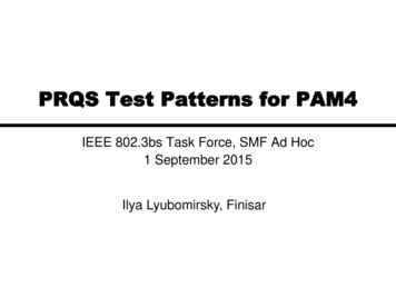
AMI Modeling for PAM4 Signaling: Tx– For NRZ, input stimulus to Tx DLL has two levels, representing 1 and 0 bits– For PAM4, input to Tx DLL needs to have four levels, representing symbols3, 1, -1 and -3 (or 3, 2, 1 and 0 in other convention)– Tx DLL interface is unchanged in PAM4PSU SI Conference2015Page 30
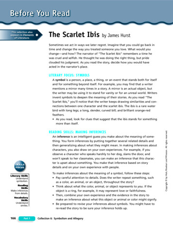
AMI Modeling for PAM4 Signaling: Rx– PAM4 Rx symbol decision relies on three slicers– Slicer reference levels are adjusted adaptively and can vary with time– Rx DLL needs to provide transient slicer levels (DT, DM and DB) to simulatorfor SER calculationNote: models for ADC based Rx need to hypothetically oversample to generate output waveformPSU SI Conference2015Page 31
AMI Simulation Flow for PAM4TxDLLTxanalogchannelRxanalogRxDLLclock timesFFEBackplaneBoardCableConnectorViaPackage AGCCTLE/FFEDFECDRDTDMDBsimulated by vendor suppliedAMI model DLLsimulated by EDA toolPSU SI Conference2015Page 32
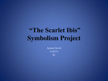
ExampleRx DLL output signalRx top slicer level (DT)Rx output eyePSU SI Conference2015Page 33
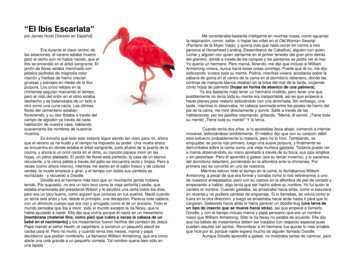
PAM-4 Measurement Challenges Clock Recovery (CR) – used to track out low-frequency jitter, trigger the scope Real-time oscilloscopes use software CR New SW algorithms required. Sampling oscilloscopes use hardware CR Existing Keysight HW clock recoverydesigns work on PAM-4 signals NoiseRN 800 uV, Eye Height 172.8 mVKeysight 86108B 50 GHz BW, RN 800 uV typical Noise will reduce eye opening and degrade system BER Random Noise (RN) from DUT TX will Root Sum Square(RSS) add to intrinsic RN from the scope\ Slower edge speeds (slew rate, S) exacerbate the issuedue to AM-to-PM conversionRN 8 mV, Eye Height 133.8 mV Sampling oscilloscopes offer the lowest noise solutionfor a given bandwidth(often 5-10x lower than a real-time scope that has equivalent BW)Eye diagram using 50 GHz Oscilloscope with 8mV rms noise.PSU SI Conference2015Page 34
Impairments that challenge PAM-4 receivers– Eye SkewSkew between top/bottom and middle eyes Electrical Considerations- Example: Skew introduced due to misalignmentof two NRZ patterns during PAM-4 generation Top and bottom eyes are skewed relative to middle eye- Standards to check alignment of middle eyerelative to upper and lower eyesEarly arrival of upper eyes Optical Considerations Eye time skew from linear drive of VCSELs(optical) Upper eyes arrive sooner than lower transitionsWill each eye need to be sampled withindependent delay? More complex RX design.PSU SI Conference2015Page 35
Other impairments that challenge PAM-4 receivers Non-linearity - Amplitude compression in lower eyes- Non uniform effective SNR across individual eyes– Receivers sensitive to additional artifacts beyond “traditional” jitter types in NRZ Still learning what impairments cause problems- New measurements WILL be defined for Tx Outputs- New stress types WILL be defined for Rx Input testingPSU SI Conference2015Page 36
Other Measurement Considerations Equalization Receiver equalization required to open eyes,allow RX to apply Forward Error Correction (FEC) Some combination of: Linear Feedforward Equalizer (FFE/LFE) Continuous Time Linear Equalizer (CTLE) Decision Feedback Equalizer (DFE)Receiver30 Gbaud, No equalization30 GBaud, 3 tap LFE (1 precursor)Apply FEC to correctbit errors.RX inputPSU SI Conference2015Page 37
QPRBS13 – Eye MeasurementsQuaternary PRBS13 Test Pattern– Types of EYE-based measurements: Eye Height Eye Width Eye Skew EW and EH likely to be specified at arelatively high probability (e.g. EW @ 1E-6) Level – mean, “thickness”, andskew at the points of minimum ISI.PSU SI Conference2015Page 38
PAM-N 86100D DCA-X: Hardware Test SolutionsElectrical and Optical solutions to 32 Gbaud (contact Keysight for 56 Gbaud solutions)Electrical – Highest Precision(includes built-in clock recovery and precision timebase)Keysight 86100D DCA-X with 86108B Channels: 2Bandwidth: 50 GHzJitter: 45 fs rms typ.Electrical Clock Recovery – integrated HW Clock Recoveryworks with PAM-N signals up to 32 GbaudNote - PAM software works with any DCA module(optical and electrical)Optical (add Electrical/TDR remote heads)Keysight 86100D DCA-X with 86105D-281 Channels: Up to 2 optical per module, 8 electricalBandwidth: 34 GHz (optical), 60 GHz (electrical)Jitter: 85 fs rms typ. (with 86100D-PTB)N1070A Optical Clock Recovery (external) 32 Gbaud Single Mode 14 Gbaud Multimode Electrical Remote Heads N1045A 60 GHz Electrical Only N1055A 50 GHz Electrical with TDR/TDTPSU SI Conference2015Page 39
Summary (IBIS-AMI) AMI Modeling (SystemVue premium services)- Industry’s only ESL flow for SerDes design spaceexploration and IBIS AMI model generationVerification in ADS lets you integrate IBIS AMIsimulation with circuits, layouts, Full wave 3DEMintegration and EM Co-simulation (FEM and FDTD) forchip-to-chip link optimizationPSU SI Conference2015Page 40
Summary (PAM-4)PSU SI Conference2015Page 41– Several industry groups and standards bodies are using, or are activelyconsidering using, PAM-4 technology Switch from NRZ to PAM-4 signaling presents manynew design and measurement challenges Keysight provides powerful solutions for: PAM-4 End-to-End Link Simulation PAM-4 TX Characterization PAM-4 RX Characterization
Feb 20, 2017 · 2015 Benefits of Automated AMI flow IBIS-AMI model ADS PAM 4 applications at 28 and 56 GB/s (DesignCon 2015) . Automatically generated .ami and Visual-Studio project Page The visual studio project automatically created - One click t