Transcription
Master BuilderCAHP Master BuilderModeling Guidelines
Master BuilderTABLE OF CONTENTS1HIGH PERFORMANCE ATTICS AND DUCTS IN CONDITIONED SPACE .11.1 Background .11.1.1 2013 Title 24 Requirements .11.2 R-30 in climate zones 2 – 10 and 12 – 16 .11.2.1 2016 Title 24 Requirements and Near-Alternatives.11.3 High Performance Attics (HPA-A and HPA-B) .31.3.1 Insulated Roof Tiles (continuous rigid foam exterior alternate) .61.3.2 Wedge-It Insulation (rigid foam external alternate) .61.4 Ducts in Conditioned Space .71.4.1 Ducts in Conditioned Plenum Space (Box or Scissor) .71.4.2 Ducts in Dropped Ceiling . 111.4.3 Ducts within a Cathedral Ceiling (finished attic). 121.5 Alternative Designs. 151.5.1 Unventilated Attic (UVA) a.k.a. Sealed Attic. 151.5.2 Ductless Systems (or No-cooling) . 182HIGH PERFORMANCE WALLS.212.1 2013 Title 24 Requirements . 212.2 2016 Title 24 Requirements . 212.3 “Above Code” Wall Insulation Options . 212.4 High Performance Wall (HPW) . 222.5 SIP and ICF Wall Assembly . 242.6 Double and Staggered Walls . 27
Master BuilderTABLE OF FIGURESFigure 1: Schematic of a high performance attic (HPA) . 3Figure 2. CBECC-Res attic roof construction assembly. 4Figure 3: CBECC-Res below roof deck insulation (HPA-B) . 4Figure 4. Ceiling (attic roof) insulation value . 5Figure 5: EnergyPro above deck insulation (HPA-A) . 5Figure 6: EnergyPro below deck insulation (HPA-B). 5Figure 7: CBECC-Res insulated roof tile . 6Figure 8: Diagrams of ducts in a conditioned plenum. 7Figure 9: CBECC-Res creating knee walls for plenum space. 8Figure 10: CBECC-Res creating construction assembly for knee wall . 8Figure 11: CBECC-Res create a distribution system . 9Figure 12: CBECC-Res ducts in conditioned space options . 10Figure 13: EnergyPro interior knee wall . 10Figure 14: EnergyPro duct location for within conditioned space . 11Figure 15: Diagram of ducts in a dropped ceiling. 11Figure 16: CBECC-Res building tree for a cathedral ceiling– Option 1 separate zone (Left) . 13Figure 17: CBECC-Res building tree for a cathedral ceiling – Option 2 main zone (Right) . 13Figure 18: Diagrams of a UVA. 15Figure 19: CBECC-Res UVA . 16Figure 20: CBECC-Res UVA roof (attic deck) insulation . 16Figure 21: CBECC-Res ceiling (attic floor) insulation with UVA . 17Figure 22: CBECC-Res duct location with UVA . 17Figure 23: CBECC-Res Cool Vent tab with UVA . 17Figure 24: EnergyPro ceiling (attic floor) insulation for UVA . 18Figure 25: EnergyPro attic insulation for UVA . 18
Master BuilderFigure 26: EnergyPro duct location for UVA. 18Figure 27: CBECC-Res ductless air distribution system . 19Figure 28: CBECC-Res no-cooling . 19Figure 29: EnergyPro ductless air distribution system . 20Figure 30: Wood framed U-factors of insulation assemblies from 2013 Title 24 JA4. 22Figure 31: CBECC-Res HPW (U-0.051) . 23Figure 32. EnergyPro HPW . 24Figure 33. EnergyPro - Import a wall assembly that is not found in the existing list . 24Figure 34: SIP wall (www.sips.org) and ICF wall (www.buildingscience.org). 25Figure 35: CBECC-Res SIP wall . 25Figure 36: CBECC-Res ICF wall . 26Figure 37: EnergyPro’s SIP wall JA4 library. 26Figure 38: Staggered wall . 27Figure 39: CBECC-Res double wall (with air gap) . 28Figure 40: CBECC-Res staggered wall . 29Figure 41: EnergyPro double wall (no air gap) . 30Figure 42: EnergyPro staggered wall . 30Figure 41: EnergyPro double wall (no air gap) . Error! Bookmark not defined.Figure 42: EnergyPro staggered wall . Error! Bookmark not defined.
Master BuilderCAHP Master Builder Modeling Guidelines1 HIGH PERFORMANCE ATTICS AND DUCTS IN CONDITIONED SPACEA high performance attic (HPA), or cool attic, minimizes temperature difference between the attic spaceand conditioned air being transported through ductwork in the attic. Locating ducts in conditioned space(DCS) further reduces the potential for unintended conditioned air transfer from ducts to unconditionedspaces.This guide details the steps for Title 24 modeling of components for High Performance Attics (HPA),Ducts in Conditioned Space (DCS), unvented attics (UVA, also known as sealed attics), and ductlesssystems. These attic-insulation arrangements are all significant improvements above traditionalinsulation methods and are all options to comply with the Master Builder program requirements. Bestmodeling methods may vary with future software releases. This guidebook is based on capabilities andfields in the 2013 CBECC-Res version 4b (812) and EnergyPro version 6.8. Similar modeling is possible for2016 Code compliance software CBECC-Res 2.0 (857) and EnergyPro 7.0.1.1 Background1.1.12013 Title 24 Requirements2013 Mandatory roof assembly and distribution system requirements R-30 (U-0.031) ceiling (attic floor) insulationR-4.2 duct insulationDuct leakage: 6%2013 Prescriptive roof assembly and distribution system requirements 1.1.2Ceiling (attic floor) insulation:R-30 in climate zones 2 – 10 and 12 – 16o R-38 in climate zones 1 and 11Radiant Barrier in climate zones 2 – 15Duct insulation:o R-6 in climate zones 1 – 10, 12, and 13o R-8 in climate zones 11 and 14 – 16Cool Roof (aged solar reflectance/thermal emittance)o 0.20/0.75 in climate zones 10-15o NR in climate zones 1-9, and 16Whole House Fan in climate zones 8 – 146% duct leakage2016 Title 24 Requirements and Near-Alternatives2016 Mandatory roof assembly and distribution system requirements Ceiling (attic floor) insulation: R-22 (U-0.043)
Master BuilderCAHP Master Builder Modeling Guidelines2016 Prescriptive roof assembly and distribution systems. Applicable in climate Zones 4, & 8-16. ForClimate zones 1-3 and 5-7, prescriptive requirements remain similar to the 2013 Code, using standardattic assemblies. Some nuanced differences apply. Please consult the 2016 Code Standards andReference Manuals for details. This modeling guide is focused on options for zones 4, & 8-16.1. High Performance Attics (HPA-A and HPA-B). Construct a standard vented attic with anadditional layer of insulation along the roof deck to regulate attic temperature.o R-38 (U-0.026) ceiling (attic floor) insulation For above deck (HPA-A): R-6 rigid external insulation above the roof deck (R-8 ifshingle roofing) For below deck (HPA-B): R-13 below deck between rafters (R-18 if shingleroofing)o Radiant barrier (for HPA-A only)o R-8 duct insulationo Cool Roof (same as 2013 Prescriptive)o Whole House Fan in climate zones 8 – 14o 5% duct leakage2. Ducts in Conditioned Space (DCS). Place all duct and air handler equipment within the thermalenvelope of intentionally conditioned space. This can be achieved with a combination of dropsoffits, plenums, interstitial space between floors, and mechanical chase ways.o Duct and air handler location confirmed by field verification and diagnostic testingo Ceiling (attic floor) insulation: R-30 in climate zones 2 – 10 and 12 – 16 R-38 in climate zones 1 and 11o 5% duct leakageo R-6 duct insulationAlternate roof assembly and distribution systems permitted in Master Builder1. Ducts located in an unventilated attic (UVA), also known as a sealed attic. Move the thermal andair barriers from the ceiling to the attic roof, eliminating attic ventilation. The attic space isn’tfully finished or intentionally conditioned. The ducts and air handling equipment is in theunventilated attic space. This option typically models with slightly worse results than the codeprescriptive requirements detailed above. This option is not the same as ducts in conditionedspace, and ducts in conditioned space modeling credit cannot be taken with this assembly.o R-22 (mandatory minimum) insulation at the roof deck (NOT at ceiling/attic floor)o Gable walls insulated as-per wall insulation standardso No attic floor insulation, and minimal air-sealing between the attic and the conditionedliving space.2. Ductless (heat pump, mini-splits, or no-cooling system). Ductless heating and cooling systems,such as mini-splits and through the wall packaged units offer an alternative to high performanceattics and ducts in conditioned space. Master Builder can accept no-cooling with exceptionalenvelope design.
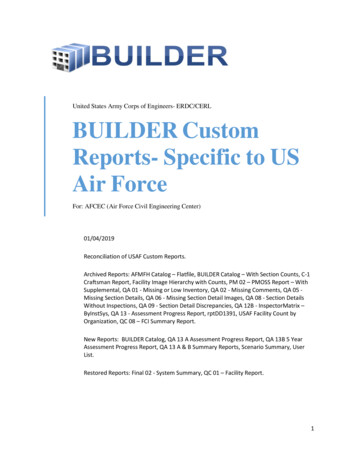
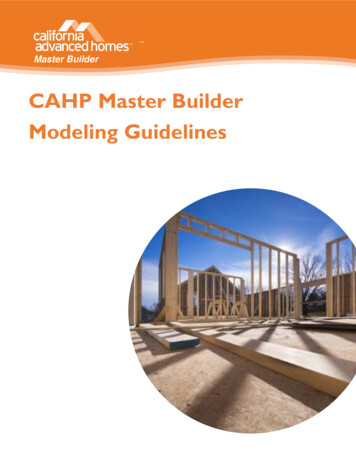
Master BuilderCAHP Master Builder Modeling Guidelines1.2 High Performance Attics (HPA-A and HPA-B)Figure 1: Schematic of a high performance attic (HPA)Source: Adapted from http://www.ductsinside.org/A high performance attic (HPA) implements measures that minimize temperature difference betweenthe attic space and the conditioned air being transported through ductwork in the attic. This designassumes that the duct and equipment are located in the attic, as is typical in current Californiaresidential construction.CBECC-ResThe ceiling (attic floor) insulation is not modeled at the attic building level; it is modeled as part of theconditioned zone as the ceiling below attic (Residential Compliance Manual for the 2013 EnergyEfficiency Standards, section 6.6.1). To model insulation that is adjacent to the roof deck, either aboveor below, a user must specify the insulation in the roof construction assembly.1. Under Envelope tab, create or edit Construction Assemblies for Asphalt, Tile, or another Rooftype with the “Can be Assigned To” Attic Roofs2. HPA-A: Select above deck insulation level (R-6, or R-8 with shingle roofing). Alternatively, ahigher than prescriptive value may be assigned3. HPA-B: Select Cavity / Frame insulation level (R-13, or R-18 with shingle roofing). Alternatively, ahigher than prescriptive value may be assigned.o This modeling assumes the assigned framing element exists throughout the depth of theinstalled insulation. If insulation will go beyond the framed cavity, and becomecontinuous as it extends past the studs (in the case of boxed netting or spray foam forinstance), the assigned Cavity/Frame insulation level may require custom calculations toaccount for and take credit for this layer of continuous insulation.4. Assign this Construction Assembly to the Attic’s Construction dropdown selection.
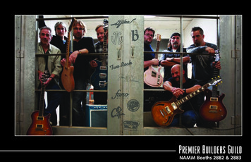
CAHP Master Builder Modeling GuidelinesMaster BuilderFigure 2. CBECC-Res attic roof construction assemblyFigure 3: CBECC-Res below roof deck insulation (HPA-B)EnergyPro1. Create or edit a roof entry in Assembly under Libraries2. In the Layers tab, select R-38 insulation for the ceiling (attic floor)3. HPA-A: In the JA-4 tab, select above deck insulation level (R-6, or R-8 with shingle roofing) forthe Added Exterior Insulation4. HPA-B: : In the JA-4 tab, select above deck insulation level (R-13, or R-18 with shingle roofing)for the Added Interior Insulation with the correct framing construction (e.g., wood)NOTE: The capability of modeling extra insulation to roof deck is not available to EnergyPro 6.6and earlier. This modeling assumes the assigned framing element exists throughout the depth of theinstalled insulation. If insulation will go beyond the framed cavity, and becomecontinuous as it extends past the studs (in the case of boxed netting or spray foam forinstance), the assigned Cavity/Frame insulation level may require custom calculations toaccount for and take credit for this layer of continuous insulation.
Master BuilderCAHP Master Builder Modeling GuidelinesFigure 4. Ceiling (attic roof) insulation valueFigure 5: EnergyPro above deck insulation (HPA-A)Figure 6: EnergyPro below deck insulation (HPA-B)
CAHP Master Builder Modeling GuidelinesMaster Builder1.2.1Insulated Roof Tiles (continuous rigid foam exterior alternate)These roof tiles are specifically manufactured to contain insulation to increase the thermal performanceof the roofing material. These tiles function similar to continuous insulation above the roof deck.CBECC-ResCBECC-Res 2013 4 adds an insulated roof tile system into the Construction library (i.e. Roofing types). Itprovides the ability of modeling an insulated roof tile system.1. Under Envelope tab, create or edit a Construction Assembly that “Can Assign to” the Attic Roof.2. Select “steep slope roof tile, metal tile, or wood shakes” as Roof Type.3. Under “Roofing” dropdown selection, three available options for insulated roof tile systems areGreen Hybrid Roofing Tile, GHR Tile with ENSOPRO, and GHR Tile with ENSOPRO Plus (detailedmaterial characteristics can be found in Table 5: Materials List, 2016 Residential ACM ReferenceManual).Figure 7: CBECC-Res insulated roof tileEnergyProAs of August 2016, EnergyPro does not have the ability to model insulated roof tiles. This capability maybe available in future software releases.1.2.2Wedge-It Insulation (rigid foam external alternate)Wedge-It insulation are wedge-shaped extruded polystyrene blocks that are installed between battensunderneath the concrete tiles. Although Wedge-It blocks are not continuous, this insulation option cancomply with Master Builder requirements, and can meet Title 24 prescriptive requirements.CBECC-Res and EnergyPro1. Assign a weighted area average R-value as a continuous exterior insulation layer on the roofdeck to represent the Wedge-It insulation.The weighted area average R-value must consider the air-gaps between Wedge-It blocks (for waterdrainage), the gaps for battens, and the tapered-wedge geometry of the Wedge-It cross section itself.
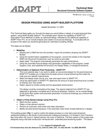
Master BuilderCAHP Master Builder Modeling Guidelines1.3 Ducts in Conditioned SpaceDucts in conditioned space credit can only be taken if all ducts, and air handling equipment is entirelycontained within finished, habitable, and directly conditioned spaces. Credit can be taken with orwithout HERS verification. HERS verification credit will lead to higher compliance. Qualifying designsinclude ducts in a conditioned plenum space, ducts in a dropped ceiling within the conditioned space,ducts in interstitial spaces between floors, and ducts under a finished cathedral ceiling. When ducts arelocated in an unventilated attic (sealed attics), they are not considered to be in in conditioned space andcredit should not be taken. For sealed attics, see section 1.4.1 Unventilated Attic (UVA) a.k.a. SealedAttic1.3.1Ducts in Conditioned Plenum Space (Box or Scissor)Figure 8: Diagrams of ducts in a conditioned plenumSource: Adapted from www.ductsinside.org and CEC2003This design creates a plenum space made within the attic that is insulated to ceiling insulation levels,sealed off from the attic, and is intentionally conditioned from the conditioned space. In the case ofscissor or box plenum trusses, the existence of an unconditioned attic zone external to the plenumspace is assumed and a critical component of the thermal pathways that determine the modelingresults.CBECC-Res1. The plenum boundary must be modeled. For a box-truss, this includes building the vertical kneewall components of the box, and accounting for the top of the box. For a scissor truss, thissimply means accounting for the extra surface area of the angled plenum top. All plenum
Master BuilderCAHP Master Builder Modeling Guidelinescomponents should be modeled either as an interior wall (i.e. knee-walls for the vertical side ofa box plenum) or a Ceiling (below attic) element.A knee wall is a sidewall separating conditionedspace from attic space under a pitched roof. Kneewalls are modeled in CBECC-Res as an interior wall(although actually a demising surface) and areinsulated as an exterior wall. (CBECC-Res 2013 UserManual 6.6.4)2. To model a knee wall (side of the box plenum):a. Create an interior wall component within the zone adjacent to the atticb. Assign the wall areac. Select the “Zone on Other Side” as Atticd. Create or edit a Construction Assembly that “Can Assign to” the Interior Walli. Set insulation to match insulation levels being used.e. Assign this assembly to the interior wall component representing the knee wallFigure 9: CBECC-Res creating knee walls for plenum spaceFigure 10: CBECC-Res creating construction assembly for knee wall
Master BuilderCAHP Master Builder Modeling GuidelinesNOTE: When creating the Ceiling (below attic) for a box plenum, ceiling area will remain the same toaccount for the insulation on top of the plenum space. If the insulation on top of the box-plenummatches the insulation used elsewhere in the attic. No separate modeling is required. If it differs, modelthis area similar to modeling an FAU platform used; build a new Ceiling below attic component andassign the surface area and a construction assembly representing the R-value of the top of the plenum.If modeling a scissor truss, model a Ceiling below attic component. The surface area should account forthe extra surface that is the result of an angled attic floor.Distribution System modeling1. Under Mechanical Tab, create or edit a Distribution System to place ducts in one of thefollowing, depending on plan:a. Duct located within conditioned space (except 12 lineal feet)b. Ducts located entirely in conditioned spacec. Verified low-leakage ducts entirely in conditioned space (NOTE: Requires HERSVerification)NOTE: For option a., the 12 linear feet limit includes the air-handler length itself. For options b. and c.,the air-handler must also be located in conditioned space. For all three options, the modeling algorithmseliminates conduction losses from internally located ducts, but will only eliminate losses due to airleakage if the user selects the verified low leakage ducts in conditioned space credit, which requiresHERS verification.Figure 11: CBECC-Res create a distribution system
CAHP Master Builder Modeling GuidelinesMaster BuilderFigure 12: CBECC-Res ducts in conditioned space optionsEnergyPro1. Create one interior wall (knee wall) in the Conditioned Zone that is adjacent to the attica. The interior wall should have the square footage of all vertical plenum surfacescombined. For example, if a plenum has two 50 sf. Surfaces, and two 25 sf. surfaces, theinterior wall would have a total of 150 sf.2. Input the appropriate information for the wall (for example, wall area and floor elevation)3. Check the Next to Residential Attic checkbox4. Click on the New Assembly field5. Select or create a wall assembly with the insulation R-value being used on the plenumDistribution systems1. Create or edit an existing HVAC system2. Click on the distribution tab at the top of the HVAC system page, and then select “Conditioned”in the Duct Location dropdown menu3. If the low-leakage ducts test will be verified by a HERS Rater, select the option of ‘Ducts inConditioned Space with Leakage Verified’ (NOTE: Requires HERS Verification)Figure 13: EnergyPro interior knee wall
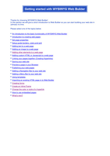
CAHP Master Builder Modeling GuidelinesMaster BuilderFigure 14: EnergyPro duct location for within conditioned space1.3.2Ducts in Dropped CeilingFigure 15: Diagram of ducts in a dropped ceilingSource: www.ductsinside.orgA dropped ceiling is a space made within the building envelope under the insulated ceiling (attic floor)that is sealed from the attic and uses the Ceiling (below attic) insulation.CBECC-ResThe only modeling action is to place the ducts and equipment in conditioned space. The thermal envelopwill be at the ceiling (attic floor) and no additional insulation or modeling requirements are necessary.NOTE: CBECC-Res will assume that HVAC equipment is also located in conditioned space. This optioneliminates conduction losses, but will only eliminate losses due to leakage if the user selects verified lowleakage ducts in conditioned space, which requires HERS verification.1. Under the Mechanical tab, create or edit the Distribution Systems for a ducts located in conditionedspace scenario. Choose one of the three options:o Ducts located Ducts located within conditioned space (except 12 ft)o Ducts located entirely in conditioned spaceo Verified low-leakage ducts entirely in conditioned space. NOTE: Requires HERSverification.
Master BuilderCAHP Master Builder Modeling GuidelinesEnergy Pro1.2.3.4.1.3.3Create or edit an existing HVAC systemSelect the distribution tab at the top of the HVAC system windowSelect “Conditioned” in the Duct Location dropdown menuIf the low-leakage ducts test will be verified by a HERS Rater, select the option of ‘Ducts inConditioned Space with Leakage Verified’ (NOTE: Requires HERS Verification)Ducts within a Cathedral Ceiling (finished attic)A cathedral ceiling is a roof that is finished on the interior and meant to be used as a habitable space. Acathedral ceiling (finished attic) is not considered an unventilated attic (UVA); the difference is that thespace below the roof deck of a cathedral ceiling is fully finished, habitable and intentionally conditioned.This design may add additional conditioned square footage to the home if it creates a loft-type space.The temperature in the space below the roof fluctuates with the rest of the conditioned space, whereasthe temperature in an unventilated attic may fluctuate separately from the conditioned space.CBECC-Res1. Create a cathedral ceiling: Delete both the Ceiling (below attic) and the Attic (if they are currently present inmodel) Create a Cathedral Ceiling for the conditioned zone. Edit or create a Construction Assembly for insulation that “Can Assign to” the CathedralCeiling (minimum R-22 insulation).i. NOTE: an Inside Finish, such as gypsum board, must be used for a habitablespace.2. Creating conditioned space below the cathedral ceiling (e.g. a loft): Option 1: If the cathedral ceiling will be in a separate conditioned zone (e.g. a loft),create a separate conditioned zone (similar to creating a second story zone)i. Omit the Ceiling (below attic)ii. Add any necessary floor over garage3. Under the Mechanical tab, create or edit the Distribution Systems for a ducts located inconditioned space scenario. Choose one of the three options:o Ducts located Ducts located within conditioned space (except 12 ft)o Ducts located entirely in conditioned spaceo Verified low-leakage ducts entirely in conditioned space. NOTE: Requires HERSverification.
CAHP Master Builder Modeling GuidelinesMaster BuilderFigure 16: CBECC-Res building tree for a cathedral ceiling– Option 1 separate zone (Left)Figure 17: CBECC-Res building tree for a cathedral ceiling – Option 2 main zone (Right)EnergyProIf the cathedral ceiling will be over the conditioned floor area of the house and does not create aseparate zone (e.g. a loft):1. Delete or edit existing roof space in the zone (if necessary) If the cathedral ceiling will only cover part of the conditioned zone, then edit theexisting roof to only reflect the portion of the roof that is not a cathedral ceiling.2. Create a cathedral ceiling for the conditioned zone(s) that it will cover Click on the New Assembly field and select a cathedral ceiling from the roof library orimport a cathedral ceiling with the appropriate insulation R-value from the JA4 Library.If the cathedral ceiling will be over conditioned space that is part of a separate zone (e.g. loft):1. Delete or edit existing roof space in the zone (if necessary) If the cathedral ceiling will only cover part of the conditioned area, then edit the existingroof to reflect only the portion of the roof that is not a cathedral ceiling.2. Create a new conditioned zone in the building tree3. Create a new room/floor in the conditioned zone In the General tab, enter the square footage and average ceiling height of the cathedralceiling4. Create a cathedral ceiling for the new room Add a roof (cathedral ceiling) to the new room/floori. The roof area should equal the floor area of the sealed attic space Click on the New Assembly field and select a cathedral ceiling from the roof library orimport a cathedral ceiling with the appropriate R-value from the JA4 Library. EnergyProuses the term ‘Rafter’ ceiling in the JA4 library to represent cathedral ceiling assemblies.
Master BuilderCAHP Master Builder Modeling GuidelinesFigure 18: Creating a Rafter/Cathedral assembly from the JA4 Library5. Add an Interior Floor to the room (e.g. loft) (this represents the floor between the new room(e.g. loft)and the floor below) If the floor of the new room (e.g. loft) is only over conditioned spacei. Add an internal floor beneath the roomii. Enter the appropriate area (should be the floor area of the sealed attic)iii. Click on the New Assembly field and enter the appropriate R-Value and detailsfor the interior surfaceiv. In the Adjacent To field, select the appropriate room If the floor of the new room (e.g. loft) is over both conditioned and unconditioned space(i.e. over living space and garage space)i. Create two separate floor surfaces; one for the area over conditioned space(interior floor), and one for the area over unconditioned space (exposed floor).ii. Enter the appropriate area for each interior surface (both surfaces should havea total area equal to that of the sealed attic floor area)iii. Click on the New Assembly field for each interior surface, and enter theappropriate R-Values and details for each interior surfaceiv. I
Master Builder CAHP Master Builder Modeling Guidelines 2016 Prescriptive roof assembly and distribution systems. Applicable in climate Zones 4, & 8-16. For Climate zones 1-3 and 5-7, prescriptive requirements remain similar to the 2013 Code, using standard attic assemblies. Some nuanced diff