Transcription
Reed-Solomon Encoder and DecoderAby Sebastian & Kareem BonnaUnderProf.Predrag SpasojevicElectrical and Computer Engineering DepartmentRutgers, The State University of New Jersey
1 IntroductionBurst Error (contiguous errors in the bit stream) is a common occurrence in digitalcommunication systems, broadcasting systems and digital storage devices. Many mechanismshave devised to mitigate this problem. Forward error correction is a technique in whichredundant information is added to the original message, so that some errors can be correctedat the receiver, using the added redundant information. Reed Solomon Encoder and Decoderfalls in the category of forward error correction encoders and it is optimized for burst errorsrather than bit errors. Reed Solomon Encoder and Decoder provide a compromise betweenefficiency and complexity, so that this can be easily implemented using hardware or FPGA.Reed Solomon code is based on the Galois Field Arithmetic. Therefore this paper firstdiscusses the Galois Field (GF) arithmetic first, and then goes into the mathematical theorybehind Reed Solomon Encoder and Decoder. As part of this project we implemented ReedSolomon Encoder and Decoder on a Lab-view environment. Section 5 discusses theimplementation of Reed Solomon Encoder and Decoder in Lab view. This paper ends withdiscussion of performance statistics generated from Lab view’s simulated Digitalcommunication channel as well as National Instruments USRP (Universal Software RadioPeripheral).2Galois Field Arithmetic2.1 Galois field (GF)Galois field consists of a elements that are generated from a primitive element, which isusually denoted by α. In this project we are using 2 as the primitive element. For a givenprimitive element α Field Elements takes values: 0, α0, α1, α2, ., αN-1, where N 2m -1. Onething we need to understand is the fact that the multiplication we use here to generate αx , isnot the normal arithmetic, but the Galois Field arithmetic which we are going to discuss later inthis section. αx , representation of Galois field elements is very useful to explain GFmultiplication and division.We can also represent GF elements as polynomial expression of form:am-1xm-1 a2x2 a1x1 a0Where am-1 a0 take the values 0 or 1. i.e polynomial representation of a GF element is nothingbut the binary number am-1am-2.a1a0 . This representation of GF element helps to describe theaddition and subtraction operation among GF elements.Addition and Subtraction operations among GF elements are same and it’s defined asfollows:
am-1am-2.a1a0 bm-1bm-2.b1b0 am-1am-2.a1a0 - bm-1bm-2.b1b0 cm-1cm-2.c1c0Where cn an XOR bnAnother important concept we are yet to define is the GF generator polynomial orprimitive polynomial p(x), which is a polynomial of degree m which is irreducible, i.e. apolynomial with no factors. In this project we are using following polynomial as p(x):x8 x4 x3 x2 1Galois field is generated on the concept that Primitive Element is a root of above equation, inGF arithmetic. There for we can write :α8 α 4 α 3 α 2 1This property will be used to derive all elements in the Galois field as described in the tablebelow:Table 1 Galois field of 256 elements
Log of GF element is defined as follows:If αx y then log(y) xLog-inverse of a GF element can be defines as follows:If αx y then log-1(x) yAfter definition of log and log-inverse it’s easy to define multiplication and division among GFelements as follows:0.a 0a.b log ( (log (a) log(b) ) modulo 255 )a/0 not defined.-1a/b log ( (log (a) - log(b) ) modulo 255 )-13 Reed Solomon EncodingReed Solomon Coding is a block coding scheme it takes a block of k symbols at a time and append 2tparity symbols. Following figure illustrates the scheme.Encoder and decoder need to agree on a encoder polynomial g(x) which is defined as :g(x)
Encoder considers the k symbol block as a polynomial, M(x); of degree k-1, and first symbol being thecoefficient of the most significant term. Encoder multiplies M(x) by x2t and divides it with polynomialg(x) to get a remainder polynomial of maximum degree 2t-1. This polynomial will be added to M(x) .x2t ,to form a polynomial which is completely divisible by g(x).Polynomial division in GF arithmetic is similar to normal arithmetic, only difference is that we will use GFaddition/subtraction and GF multiplication in this scheme. Diagram below illustrates a GF polynomialdivision of a degree 10 polynomial by a degree 4 polynomial. To reduce complexity here we are using aGF(2 4) field, but in our project we are using GF(2 8).4 Reed Solomon DecodingReed-Solomon Decoder consider the incoming message as a polynomial R(x), transmitted message asT(x) and Error introduced as polynomial E(x). i.e.
R(X) T(x) E(x)Now the Decoder problem is to identify the E(x) so that T(x) can be calculated as follows:T(X) R(x) E(x)4.1 SyndromesWe know that the T(x) is perfectly divisible by g(x) . Therefore in case of no errors; for‘I’ in [0, 2t-1], g(must evaluate to zero. When there are errors, some or all of them will result in anon-zero value and that value is called syndromei (Si ) is defined as :Si R( T( E( Y1 Y2 Yvii Y1X1 Y2X2 YvXviWhere e1, e1 ev are the locations of error and Y1, Y2 Yv are the corresponding coefficient/magnitudeof the Error polynomial E(x).And also Xj .4.2 Error Locator polynomialAssuming ‘v’ is the degree of the error polynomial; we can write Error Locator Polynomial as:Λ(x) (1 X1x) (1 X2x) (1 Xvx) 1 Λ1x1 Λv-1xv-1 ΛvxvRoots of the above equation Λ(x) are X1 -1, X2 -1, . Xv -1Therefore we can write:1 Λ1Xj-1 Λv-1Xj-v 1 ΛvXj-v 0Multiplying both sides by YjXj i v :YjXji v Λ1 YjXji v-1 Λv YjXj1 0We can create similar equation errors for different values for Xj and terms collected together gives: Si v Λ1 Si v-1 Λv Si 0
We can derive 2t-v simultaneous equation by substituting ‘I’ with different values in [0, 2t-v-1].Easiest way to solve the above equation is using Berlekamp’s algorithm.Berlekamp’s algorithm computes the coefficients of Λ(x) equation using following variables:a correction polynomial C(x) which is initialized to ‘x’.syndrome values S0, S1, S2t-1.L, current number of assumed errors; initialized to 0.N, total number of syndromes, main loop of the algorithm will be executed N times.B(x), copy of C(x) when L was last updated; initialized to 1.d, discrepancy in C(x) calculated every iteration.b, copy of d when L was last updated ; initialized to 1.m, number of iteration since L was last updated.Algorithm is as listed below: Each iteration , algorithm calculates the discrepancy d; on kth iteration ‘d’ is calculated usingformula:d Sk C1Sk-1 . CLSk-L If d is zero, algorithm assumes that C(x) and L are correct for the moment, increments m andcontinue. If d is not zero a new C(x) will be calculated as follows:C(x) C(x) – (d/b)xm . B(x) and L, b, B(x) and m will be updated. If the number of errors are less than or equal to N/2, then C(x) will contain Λ(x) on or beforeNth iteration.Once we have the coefficients of Λ(x) , finding X1, X2 Xv is very easy because X1 -1, X2 -1, . Xv -1, are theroot of equation Λ(x) and also we know that Xj and j is in [0,n-1], where n is length of code. So weuse Chein search, method on Λ(x) to identify Xj eventually all ej. Chein search method is very simple, itevaluates given polynomial for all possible roots, in our case total n; if equation evaluates to zero thenthat value assigned to ‘x’ is considered as a root.4.3 Error polynomial CoefficientsWe use Forney’s algorithm to calculate Yj.
Yj Xj [ Ω ( Xj -1 )/ Λ’( Xj -1 ) ]Where Ω ( x) S(x) . Λ( x ) mod x 2t ; i.e S(x) . Λ( x ) with all terms above degree 2t-1 ignored.And Λ’( x ) is the first derivative of Λ( x ).Λ’( Xj -1 ) Λ1 Λ3 Xj -2 Λ5 Xj -4 5 ImplementationThe Reed-Solomon Encoder and Decoder were implemented as part of an existing QPSK transmitter andreceiver with key modules replaced by us in the lab. The notable modules that were replaced were thebit generator and BER calculator, the symbol mapper and demapper, the pulse shaping and matchedfilter, and some parts of the synchronization.The Reed-Solomon code generator polynomial used was based off of the n 255, k 239 code. In mosttesting the code was shortened to n 32, k 16 via code shortening (populating the initial 239-16 symbolswith zeros).Software implementation of the Reed-Solomon Encoder and Decoder, and additionally parts of thebaseband transmitter and receiver were done in LabVIEW. Testing was performed both in softwareusing a simulator and in hardware using the NI USRP software defined radio.5.1 Generic VisBits - Symbols, Symbols - Bitsrs bits to symbols.vi
rs symbols to bits.viThese VIs convert a stream of bits into a stream of symbols in GF(256) and vice-versa. This is done bygrouping and ungrouping sets of 8-bits.GF Log Lookup, Inverse Log LookupGFLog.vi
GFElement.viThe log lookup VI takes an element in GF(256) and returns the power that the primitive element israised to using the field generator polynomial. The inverse log lookup VI takes an integer from 0-255,and then returns the element in GF(256) that corresponds to the primitive element in the field raised tothat power, using the field generator polynomial.GF Multiply, Divide (Log Lookup)GFMult orig.vi
GFDiv.viThe Log lookup GF multiply and divide VIs take two elements in GF(256), do a log lookup to get theirexponents, add or subtract the exponents, and then does an inverse log lookup to get the resultGF Multiply (Iterative)GFMult.viThe iterative GF multiply VI takes two elements in GF(256) and multiplies directly using the generatorpolynomial, adding the polynomial back in when there is overflow. In a practical implementation thismethod would be slower, however in LabVIEW it runs faster than the log lookup method.GF Polynomial EvaluateGFPEval.vi
This VI takes an array of coefficients of a GF(256) polynomial and evaluates it at some input value.Erasure Channelbec.viThis VI emulates an erasure channel by replacing symbols with their inverted counterparts.5.2 R-S Specific VisRS Encoder
rs encoder.viThe RS Encoder is a LFSR that is used to calculate the remainder of polynomial division by the expandedcode generator polynomial g(x). After shifting the message polynomial through, the registers hold theremainder which are the parity symbols that are appended to the message.Syndrome CalculationSyndromeGen.viThe syndrome generator VI is used to evaluate the message polynomial at the roots of the codegenerator polynomial. All of the syndromes are zero when there is no error since the messagepolynomial is perfectly divisible by all roots.Berlekamp’s Algorithm
BerlekampsAlg.viBerlekamps Algorithm is used to compute the error locator polynomial, used to determine the errorlocations and error magnitudes.Omega CalculationOmegaCalc.viThe Omega Calculator VI calculates the Omega polynomial, used in Forney’s algorithm to compute theerror magnitudes.
Chien SearchCheinSearch.viThe Chein Search evaluates the error locator polynomial at the possible roots in GF(256) to determinethe error locations in the message.Forney’s Algorithmforney.viForney’s Algorithm computes the error magnitudes using the Omega and Lambda (error locator)polynomials.
5.3 Encoder ImplementationRS Block Encoders top encoder.viThis vi takes an array of elements in GF(256) and splits them into blocks of k to be encoded.RS Top-level Encodertop rs enc.viThis is the wrapper for the encoder so that the inputs and outputs are bitstreams
5.4 Decoder ImplementationRS Decoderrs decoder.viThe decoder VI pulls the syndrome calculation, error locator polynomial calculation (Berlekampsalgorithm), error location and error magnitude (Forney’s algorithm) calculations together to produce thecorrected block of k symbols out.RS Block Decoders top decoder.viThis vi takes an array of elements in GF(256) and splits them into blocks of n to be decoded.
RS Top-level Decodertop rs dec.viThis is the wrapper for the decoder so that the input is the encoded bitstream and the output is thedecoded bitstream.5.5 Transmitter and ReceiverTransmittertransmitter.viThis VI has the QPSK transmit chain from the lab, with the RS encoder block inserted prior to symbolmapping.
Receiverreceiver.viThis VI has the QPSK receive chain from the lab, with the erasure channel block inserted after thedecoder and also the RS decoder inserted after the symbol demapper.5.6 Top-level VIsSimulatorrs simulator.viThe simulator is used to tie the transmitter and receiver together with an artificial channel and simulatetransmitting and receiving packets. It either can run the simulator for static settings or, if loop-plot is
enabled, will vary the input settings for either noise-power for AWGN or p(e) for an erasure channel andplot the corresponding BER curves.Transmittertop tx.viThis VI is used to transmit data using the physical USRP.Receivertop rx.viThis VI is used to receive data using the physical USRP. It can also plot points for BER vs SNR.
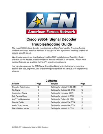
6 Performance ResultIt should be noted that all simulations and hardware experiments used the following settings:Message Length (data)128 bitsn32Sample rate4M Samples/sec.k16Oversample factor20 Samples/symbolPulse shapeRoot-raised CosineSymbol rate200K Symbols/sCenter frequency915.0 MHz6.1 Single RunThe following is a received signal constellation:This matches the expected transmitted QPSK signal constellation with the energy normalized to 1.The eye diagram follows:
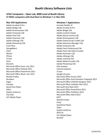
This also matches the expected eye diagram. The period matches the symbol period.6.2 AWGN Channel PerformanceThe following figure plots the BER versus noise power (N0) in an AWGN channel using simulation. TheReed-Solomon code used was n 32, k 16.
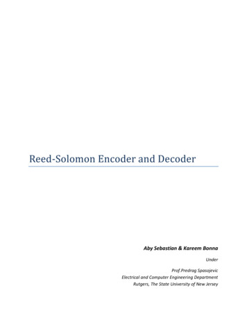
There is not a significant improvement using Reed-Solomon coding in an AWGN channel. This result isnot surprising given that Reed-Solomon codes work well in correcting burst errors, where many bits insequence are in error. In the AWGN case, bit errors happen randomly, so the burst-error correctingcapability is not fully utilized (just 8 bit errors spread across 8 symbols will max out the error correctioncapability).6.3 Binary Erasure Channel PerformanceThe following figure plots the BER versus p(e), the probability of a symbol erasure in a Binary ErasureChannel using simulation. The Reed-Solomon code used was n 32, k 16.There is a significant reduction in the BER, particularly when p(e) 0.25. This is not surprising since thecode is able to correct up to T 8 symbols, or one quarter of the message symbols in error.6.4 Power Spectral DensityPower spectral density is given below for two captures on the USRP using antennas, one without anyerror-correction coding and one utilizing Reed-Solomon Coding. The x axis is in units of Hz away fromthe center frequency (915 MHz) and the Y axis is in units of dB.
Figure 1: Power Spectral Density without RS-CodingFigure 2: Power Spectral Density with RS-CodingFrom the figure, it is observed that the bandwidth of the signal is around 200KHz, which is also thesymbol rate. There is no noticeable difference when Reed-Solomon coding is added.7 References[1] Polynomial Codes over Certain Finite FieldsReed, I.S. and Solomon, G.
[2] RS Coding Explanation & ImplementationC.K.P. df-files/WHP031.pdf[3] An introduction to Reed-Solomon codes: principles, architecture and implementationMartyn Riley and Iain Richardsonhttp://www.cs.cmu.edu/ guyb/realworld/reedsolomon/reed solomon codes.html[4] Reed Solomon CodesJoel Sylvesterhttp://www.csupomona.edu/ jskang/files/rs1.pdf[5] Reed Solomon CodesBernard Sklarhttp://hscc.cs.nthu.edu.tw/ sheujp/lecture note/rs.pdf[6] 802.16-2004 802/download/802.16-2004.pdf[7] The Finite Field GF(28)(GF Multiplier Implementation)Neal R. Wagner
Software implementation of the Reed-Solomon Encoder and Decoder, and additionally parts of the baseband transmitter and receiver were done in LabVIEW. Testing was performed both in software using a simulator and in hardware using the NI USRP software defined radio. 5.1 Generic Vis Bit