Transcription
Basic Wiring for Motor ContolTechnical DataTable of ContentsNew InformationApril artStop1MA132OLA295M96Language of Control . . . . . . . . . . . . . . . . . . . . . . . . . . . .Symbols . . . . . . . . . . . . . . . . . . . . . . . . . . . . . . . . . . .Circuitry of a Starter . . . . . . . . . . . . . . . . . . . . . . . . . . . .Two-Wire Control. . . . . . . . . . . . . . . . . . . . . . . . . . . . .Three-Wire Control . . . . . . . . . . . . . . . . . . . . . . . . . . .Control Power Transformers . . . . . . . . . . . . . . . . . . . . . .Control Circuit Wiring of CPTs . . . . . . . . . . . . . . . . . .Reversing Starters . . . . . . . . . . . . . . . . . . . . . . . . . . . . . .Cover Control Circuits . . . . . . . . . . . . . . . . . . . . . . . . . . .Start/Stop with Pilot . . . . . . . . . . . . . . . . . . . . . . . . . .Hand/Off/Auto . . . . . . . . . . . . . . . . . . . . . . . . . . . . . . .Forward/Reverse with 2 Pilots . . . . . . . . . . . . . . . . . .Glossary . . . . . . . . . . . . . . . . . . . . . . . . . . . . . . . . . . . . . .IntroductionA Refresher Course for the Product ModifierThis text is designed as a refresher course for personnelwho will have the responsibility of modifying CutlerHammer products from Eaton’s electrical business tomeet their customer’s needs.The scope of the material has been necessarily limited. Itcovers the most commonly used products and wiring schematics. Despite its brevity, you are cautioned not to skimlightly over the content.The Benefit of Satisfaction and ConfidenceThere is great satisfaction in being “good” at something.Individuals who attain knowledge in a particular field haveconfidence and the respect of their associates.Studying this text will provide you with a fundamental andsolid knowledge of control wiring and the products you willbe working with.When you are able to offer your customers tailor-made solutions to their product needs, you are sure to feel great satisfaction. And, when your endeavors help add to theprofitability of your organization, you will very likely enjoygreater benefits.We hope you agree after finishing this course of study.TD03309004EFor more information visit: www.eaton.comPage2346689101111111213
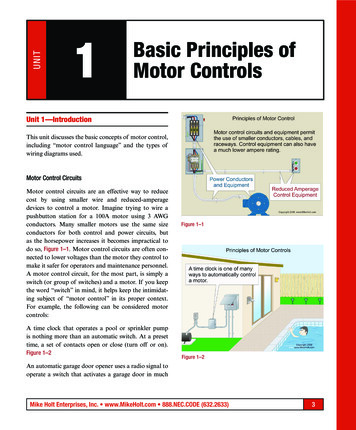
Technical DataPage 2Effective: April 2007Basic Wiring forMotor ContolLanguage of ControlCircuit diagrams communicate information quickly andefficiently.Line diagrams show circuits of the operation of thecontroller.Every trade and profession has its method of communicating ideas and information quickly and efficiently. In additionto the terminology shown in the glossary of this text, diagrams play a vital role of communication in electrical circuits. A knowledge of symbols, diagrams and terminologywill aid in our understanding of electrical control.Line diagrams, also called “schematic” or “elementary” diagrams, show the circuits which form the basic operation ofthe controller. They do not indicate the physical relationships of the various components in the controller. They arean ideal means for troubleshooting a circuit.The basic language of control is the circuit diagram. Consisting of a series of symbols interconnected by lines to indicatethe flow of current to the various components, it tells inremarkably short time a series of events that would takemany words to explain. Circuit diagrams are available in twoformats.Figure 2 shows a typical line or schematic ure 1 is a typical wiring diagram for a three-phase magnetic starter.L1OLL2Wiring diagrams show the connections to the controller.Wiring diagrams, sometimes called “main” or “construction” diagrams, show the actual connection points for thewires to the components and terminals of the controller.They show the relative location of the components. They canbe used as a guide when wiring the controller.ML11MA132MOLA29596Figure 2. Typical Line or Schematic PhaseMotorFigure 1. Typical Wiring DiagramFor more information visit: www.eaton.comTD03309004E
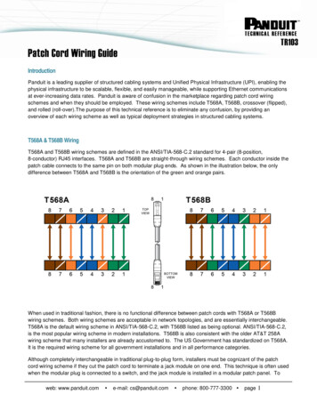
Basic Wiring forMotor ContolTechnical DataEffective: April 2007Page 3SymbolsStandardized symbols make diagrams easier to read.Both line and wiring diagrams are a language of pictures. Itis not difficult to learn the basic symbols. Once you do, youare able to read diagrams quickly, and can often understanda circuit at a glance. The more you work with both line andwiring diagrams, the better you will become in analyzing them.The American Standards Association (ASA) and the NationalElectrical Manufacturers’ Association (NEMA) are the agencies which are responsible for setting up and maintaining thesymbol standards. Because of these standards, you will beable to read all diagrams that come across your workbench.Figure 3 shows many of the most commonly used symbolson Control diagrams.CoilsSingle VoltageMagnet CoilsDual VoltageMagnet CoilsOn Contacts and Switches or Pushbuttons, you will find adesignation of NO or NC (Normally Open or NormallyClosed). This refers to the state of the contacts when poweris not applied to them. In tracing circuits on line diagrams,you will need to visualize the opening or closing of the contacts when the circuit is energized or de-energized.The pushbutton symbols shown in Figure 3 represent“Momentary” pushbuttons. The contacts will change statefrom their normal position only for as long as your finger ison the button.Later in this text, we will be working with actual applicationsand line diagrams. So study these symbols carefully please.RelaysThermalOverload9897OLLink96Reset9512 .C.T.O.1 23 4LowVoltageSwitchesT.O.PushbuttonNormally ClosedPushbuttonContactsNormallyOpenNormally OpenLimit SwitchNormallyOpenNormallyClosedLimit SwitchHeld OpenLimit SwitchNormallyClosedTimedOpenT.O.Limit SwitchHeld eStandardIndicatorLightsStandardMotors haseT1T2Two-WirePilotDevicesT3TransformersLow VoltageControlTransformerH1X1Figure 3. Standard Diagram SymbolsTD03309004EFor more information visit: www.eaton.comPTH2X2
Technical DataPage 4Effective: April 2007Basic Wiring forMotor ContolCircuitry of a StarterThe two circuits of a motor starter are the power and control circuits.There are two circuits to a starter — the Power Circuit andthe Control Circuit.The electricity that passes through the contacts of thestarter, through the overload relay, and out to the motor, iscalled the power circuit. The thick lines of Figure 4 representthis power circuit. It is the power circuit that passes electricity to the motor enabling it to run. For this reason, it is sometimes referred to as the motor circuit.Common Control — power and control circuits at same voltage. Separate Control is at different voltages.The thin lines in Figure 4 represent the control circuit. Themagnet coil of the starter is energized with this circuit, whichcreates the electro-magnetic field that pulls the power circuitcontacts closed.The control circuit is separate from the motor circuit. Thecontrol circuit may not be at the same voltage as the powercircuit. When the voltage of the control and power circuits isthe same, it is referred to as Common Control. If the voltages are different, it is called Separate set953-PhaseMotorSeparate voltages supplied by Control Power Transformers.Another method for supplying separate voltages for powerand control circuits, is to use a Control Power Transformer.These are sometimes also referred to as Control CircuitTransformers. One voltage source is used to supply themotor. This same voltage is also supplied to the primary sideof the transformer. The transformer’s secondary supplies thevoltage to operate the magnet coil in the control circuit. Amore detailed explanation of transformers can be found onPage 8.Common Control is when the power circuit and the controlcircuit are fed from the same voltage source.Common control is when the control circuit is tied back tolines 1 and 2 of of the starter. It is supplied with the samevoltage as the power or motor circuit.The understanding of Common Control and Separate Control becomes significant when changing magnet coils fromone voltage to another.Changing magnet coils from 120V or to 120V involves adding or removing wire “C”.If you stock starters or contactors with different rated magnet coils, and need to convert the device to a 120V magnetcoil for separate control, you must remove the connection tothe power circuit that is provided. Figure 5 shows this connection. Wire “C” is connected to L2 and terminal 96 on theoverload relay in all Cutler-Hammer starters supplied withmagnet coils greater than 120V. You must remove the wire,and then connect the separate control voltage lines to thenumber 1 terminal on the remote pilot device and terminal96 on the overload relay.On the other hand, if you are converting a starter that wasfactory supplied for 120V Separate Control to a CommonControl device, you must put in this jumper.If you are swapping out a 480V magnet coil to supply onewith 240V coil to meet a customer’s needs, you do not needto worry about wire “C”. Only when changing to 120V orless from any voltage greater than 120V or changing to anyvoltage greater than 120V from 120V or less, is thissignificant.Figure 4. Typical Starter Wiring Diagram — Three-PhaseSeparate voltages supplied by different voltage sources.How can you have two different voltages going into thesame starter? One method is to run different wires from different electrical voltage sources. You might have a 480V supply that is attached to the line side of the starter, and thatruns through to the motor. Another set of wires, from a different voltage source would bring 120V to the magnet coil.The coil is energized by the 120V, and the pushbuttons orother control devices operate at this same voltage. Themotor operates at the power circuit voltage, in this case,480V. The coil rating must match the control source voltage,and the starter is sized to match the horsepower and voltageratings of the power circuit.For more information visit: www.eaton.comTD03309004E
Basic Wiring forMotor ContolTechnical DataEffective: April 2007Page 5Circuitry of a StarterCommon Control1/L13/L25/L31A12A2Remote PilotDevicesCì ”M2-Wire Control31983Not for use with AutoReset OL Relays.97OL962/T14/T2Reset6/T3953-Wire ControlSeparate ControlT1T2StartRemove Wire “C” when it issupplied. Connect SeparateControl Lines to the No. 1Terminal on the RemotePilot Device and theTerminal 96 on theOverload Relay.T332Stop3-PhaseMotor1/L1Separate Control 16/T3T2Reset95T33-PhaseMotorFigure 5. Common vs. Separate ControlTD03309004EFor more information visit: www.eaton.com1
Technical DataPage 6Effective: April 2007Basic Wiring forMotor ContolCircuitry of a StarterTwo-Wire ControlTwo-Wire Control circuits — or Low Voltage ReleaseOne of the common control wiring circuits used is known asTwo-Wire or Low Voltage Release (LVR). It utilizes a maintained contact type of pilot device — such as a thermostat,float switch or presence sensor. Figure 6 shows the line andwiring schematics for this circuit.When the maintained contacts on the pilot device are closed,it energizes the coil of the starter, which connects the loadthrough the power circuit. When the contacts of the pilotdevice open, the coil is de-energized, and the starter dropsthe load off line.Automatically restarts when power is restored if pilotdevice is still closed.The circuit provides for an automatic operation of the load.If there is a power outage or loss, the starter will bede-energized. This is why the circuit is often called LowVoltage Release (LVR).1/L13/L25/L311A1A22Two-WirePilot DeviceM3989796OL2/T14/T26/T3T1T2T3If the maintained contacts of the pilot device remain closedduring the power loss or outage — the starter will be reenergized when the power to the control circuit is restored.2Reset95L1Caution must be used in the application of this circuit —there is no personnel safety protection when the power isrestored.L2PD3-PhaseMotor1A1MOLA295396Figure 6. Two-Wire ControlThree-Wire ControlThree-Wire Control circuits — or Low Voltage ProtectionThe other very common control wiring circuit used is knownas Three-Wire or Low Voltage Protection (LVP). This circuitrydoes provide personnel safety protection in the event ofpower loss or outages. It utilizes momentary contact pilotdevices and a holding circuit contact.L1L2L31A1A2This holding circuit, or seal-in circuit, is most commonly provided by an auxiliary contact on the contactor or starter.Figure 7 shows the typical line and wiring diagrams forThree-Wire control circuits.Circuit does NOT automatically restart when power isrestored.This circuitry provides LVR, because if there is a power outage or loss, the starter will be de-energized. But, it providesLow Voltage Protection, because the circuit does not automatically restart. The only way to restart this circuit is tomanually use the START button.Because this circuit is very popular in motor control systems, let’s go through the operation of it -PhaseMotorFigure 7. Three-Wire ControlThe circuit consists of a Normally Closed (NC) STOP buttonwired in series with a Normally Open (NO) START button. ANormally Open (NO) Auxiliary contact on the starter will beused as the holding circuit.For more information visit: www.eaton.comTD03309004E
Basic Wiring forMotor ContolTechnical DataEffective: April 2007Page 7Circuitry of a StarterThree-Wire Control (Continued)When the START button is depressed (Figure 8), it completesthe circuit to energize the coil of the starter. When thatoccurs, the Normally Open (NO) Auxiliary contact closes.This auxiliary is shown as M on the line diagram.L1L2StopStartOLMMWhen power is restored, the circuit CANNOT automaticallyrestart because the START button needs to be pushed tocomplete the circuit. Because someone must manuallyrestart the circuit, this can provide a means of personnelsafety.As we saw in the common vs. separate control wiring, thecontrol circuit is connected through a contact on the overload relay. When an overload is detected, this contact opensthe circuit and de-energizes the coil. If you are using a ThreeWire control circuit, then the starter cannot automaticallyrestart — the Start button with its NO contacts prevent thecircuit from being completed.L1L2Figure 8. START Button Completes CircuitStopWhen you remove your finger from the START button, itscontact returns to the Normally Open state. Even though thisopens a path to the coil, the circuit now travels through theclosed M contact to keep the starter energized.The electricity flows from L1, through the Stop (NC), throughthe path completed when contact M closed, to the coil,through the overload relay control circuit, to L2 ( Figure 9).L1L2StopStartOLOLMMFigure 10. STOP Button Opens CircuitWith 3-Wire control, automatic reset on an overload relaywill NOT re-energize the circuit.There is sometimes confusion with overload relays thathave an Automatic Reset capability.In a Three-Wire circuit, with the overload relay set for Manual Reset, both the RESET button on the overload, as well asthe START button, must be used to re-energize the circuit.MMAn overload relay in the Automatic mode would not automatically re-energize the circuit, because the START buttonis still open.Figure 9. Electrical Path is through Contact MPressing the STOP (Figure 10) button will cause the Normally Closed (NC) contact to open the circuit, de-energizethe coil, and drop out contact M. Releasing the STOP buttonwill return the circuit to its original (off) state.An overload relay with Automatic Reset, used with a twowire circuit would provide automatic restart. This type of circuitry must be used only on applications where personnelsafety is not an issue.If there is a power outage or loss, the coil is de-energized,contact M opens, and the starter drops the load off line.TD03309004EStartFor more information visit: www.eaton.com
Technical DataPage 8Effective: April 2007Basic Wiring forMotor ContolControl Power TransformersWhy use a Control Power Transformer?The motor branch circuit is usually a segment of a largerelectrical distribution network in an industrial plant. Themotor circuit supplies the required power to the various control devices in order for them to operate. In some cases, thevarious control devices are operated at the same voltage asthe motor. Sometimes, the voltage required to operate themotor is too high to safely operate the control circuit, particularly in regards to personnel safety. As a means of reducingthe motor voltage to a safer control voltage level, we use adevice known as a Control Power Transformer.Connected with the Primary winding to the Power circuit —Secondary winding to the Control Circuit.A typical control transformer is shown in Figure 11 below. Itconsists of two separate coils of wire (windings) placed adjacent to each other on a common iron core. Note that the primary winding is connected to the power source. Thesecondary winding is connected to the control circuit. Thepurpose of the transformer is to transfer electric power fromthe primary circuit to the secondary circuit. The transformereither reduces (steps down) or increases (steps up) the voltage to match the requirements of the control circuit.Magnetic field from primary winding induces voltage in thesecondary winding.Applying AC voltage to the primary winding of the transformer causes alternating current to flow in the winding.This produces a magnetic field that extends outside thewinding, in the shape of concentric loops as shown inFigure 12. The magnetic field fluctuates as the AC changesdirection. These magnetic lines cut across the conductors ofthe secondary winding and induce a voltage.Magnetic Field of Primary Winding Expands andContracts as AC Current Flow Increases and Decreases.AC PowerSourceLoadVoltage Induced inSecondary WindingFigure 12. AC Flow in WindingsVoltages based on number of turns on both windings.Primary WindingConnected toAC Power SourceIron CoreFigure 11. Typical Control TransformerSecondary WindingConnected to LoadThe relationship of the voltage across the primary to thevoltage across the secondary is in direct proportion to thenumber of turns on both windings. For example, 100 turnson the primary, and 10 turns on the secondary, is a 10 to 1ratio. If the primary is 500 volts, we will get 50 volts at thesecondary. This is referred to as a Step-Down transformer.They are most commonly used in control circuits where themotor voltage is 480V, 600V, or higher. The step-down control transformer would reduce the voltage to pushbuttons orPLCs to 120V or even 24V.A transformer with the reverse proportion of more turns onthe secondary winding than on the primary is called a StepUp transformer. It will increase the voltage according to theratio of turns.For more information visit: www.eaton.comTD03309004E
Basic Wiring forMotor ContolTechnical DataEffective: April 2007Page 9Control Power TransformerPrimary connects to the power circuit — Secondaryconnects to the control circuit.The schematic symbol for the transformer is represented bytwo groups of “scallops” facing each other. These representthe primary and the secondary windings. The winding withthe higher number of turns should be shown to have morescallops than the other to identify it as either a step-down orstep-up transformer.Connections for DualVoltage TransformerL1240V480VH1 H3 H2 H4H1 H3 H2 H4H1 H3 H2 H4(Primary)X1X2StartMA1 A2 OL2 M 395 96 GStop1(Secondary) 1/ 3/ 5/X2 120V X1L1 L2 L3Figure 13 shows a basic control circuit with a step-downtransformer added. Note that the main motor circuit operates at 480V, while the control circuit is at 120V.H1H3 H2H4A1 A2G2M3CPTThe primary winding of the transformer is connected to twophases of the power circuit. The secondary winding is connected to the control circuit.L2H1 CPT H4StartX298X1OL2/ 4/ 6/T1 T2 T319796Reset9532Stop 1T1 T2 T33-PhaseMotorFigure 13. Control Circuit with CPTControl Circuit Wiring of CPTsMagnet Coil and Pilot Lights rated for same voltage as Secondary of Transformer.When you are installing a Control Power Transformer into astarter, you must be sure that the magnet coil is rated for thesame voltage as the secondary of the transformer.In addition, any pilot lights in this circuit must have the samevoltage as the secondary.The leads from the secondary of the transformer are connected to Terminal 1 of the remote pilot device, and terminal96 on the Freedom Series overload relay (see Figure 14).Note: Connections for DualVoltage Rated Transformersee Transformer Nameplate.CPTDual Voltage units shipped with connections made for thehigher voltage.When you are using a Control Power Transformer with adual voltage primary, check the transformer connections tobe sure that they match the voltage of your power source.Cutler-Hammer transformers with dual voltage primaries(i.e. 480V and 240V) are shipped with the transformer connections made to supply the higher voltage. If the lower primary voltage is required for your application, change theconnections as shown on the nameplate of the transformer.To Terminal L1on the Starter.Figure 14. CPT Wiring DiagramFor more information visit: www.eaton.comTo Terminal L2on the Starter.BLKG1To Terminal 1 on theRemote Pilot Device.REDTo Terminal 96 onthe Overload Relay.The leads from the primary of the transformer are connectedto L1 and L2 on the starter. In this way, the primary of thetransformer is supplied with the same voltage as the power/motor circuit of the starter.TD03309004EX1 L2BLKGround Wire (Green)remove if not required.Remove wire “C”, if supplied, from starter’s control circuit.As discussed earlier in this booklet, if wire “C” is supplied onthe starter (magnet coil voltages greater than 120V), youmust remove it. This will convert the starter from CommonControl to Separate Control.X2L1
Technical DataPage 10Effective: April 2007Basic Wiring forMotor ContolReversing StartersTo reverse a motor, you reverse the leads to the motor.To reverse a motor, you need to reverse the leads to themotor. When using a reversing magnetic starter, this task isaccomplished using two contactors, one overload relay, anda mechanical interlock. The control circuit is designed to provide an electrical interlock as well.L1LinesL2 L3Contactors “F” and “R” areMechanically InterlockedFRBoth the mechanical and electrical interlocking prevent thesimultaneous operation of the forward and reverse contactors.FFigure 15 shows the wiring diagram for a full-voltage magnetic reversing starter.RWhen the forward contacts (F) close, L1, L2, and L3 are connected to T1, T2, and T3, just as they would be on a nonreversing starter.FWhen the reverse contacts (R) close, the motor is connectedL1 to T3, L2 to T2, and L3 to T1. On a three-phase motor, it isnecessary to change only two leads in order to reverse therotation of the motor.OLT1T2OLT3OLRStop1“C”ForREVFLS R2MotorF3A1 F A26OL9596(If Used)Pushbutton with“FOR” and “REV”Buttons Electrically4Interlocked.1For1/L13/L2RLS F5/L34RevStop27451R7RearRear23R52L1A13FL2 L3A23Figure 16. Reversing Starter Line DiagramA1 A24R56“B”598“A”Separate Control97OL96Remove Wire “C”“C”2/ 4/6/Resetwhen it is supplied.T1 T2T395Connect SeparateControl Lines tothe No. 1 TerminalFLSRLSon the remote3657pilot deviceand TerminalT1 T2 T3When Limit Switches areNo. 96 on theused, omit Connectors “A”overload relay.and “B” and connect perDotted Lines.MotorThis circuit operates as follows: Depressing the FORWARDpushbutton energizes coil F, completing the circuit from L1to L2.Coil F energizes NO auxiliary contact F, closing it for theholding circuit.Coil F also operates NC auxiliary contact F, opening it toinsure that coil R cannot be energized.The mechanical interlock physically prevents the power contacts of contactor R from operating.When the STOP button is pushed, the entire circuit is deenergized. All of the contacts return to their normal state.The REVERSE pushbutton can then be depressed to operatethe reverse contactor.Mechanical Interlock prevents simultaneous operation.Pressing the REVERSE button allows current to energize coilR to complete the circuit to the motor. Power can flowthrough NC contact F, since coil F is not energized. When coilR is energized, NO contact R acts as the seal-in contact.To keep the forward and reverse contacts from operatingsimultaneously, a mechanical device is used.In this control circuit, the STOP button must be operatedbefore the direction of the motor can be changed.This device mounts in between the two contactors and physically prevents the power contacts from operating at thatsame time.The power circuit connections reverse the rotation of themotor.Figure 15. Reversing Starter Wiring DiagramControl circuitry provides an electrical interlock to preventoperation at the same time.Additionally, the control circuits are wired in such a way asto prevent simultaneous operation. This is done with the useof Normally Closed (NC) auxiliary contacts.As the coil of one direction contactor is energized, its associated NC contact opens — insuring an open electrical path tothe coil of the opposite contactor’s coil. Figure 16 shows thiscircuitry.Refer back to the wiring diagram ( Figure 15). Trace thepower circuit lines connected to Coil R.A connection at L1 is traced through the power contacts, andconnected to T3, through the overload relay and to the motor.The connection at L3 is traced through to be connected at T1.L2 is connected to T2 as it would be in a non-reversing starter.It is these connections that reverse the rotation of the motor.For more information visit: www.eaton.comTD03309004E
Basic Wiring forMotor ContolTechnical DataEffective: April 2007Page 11Cover Control CircuitsThere are many basic control circuits.We will be reviewing many basic control circuits. We willlook at both the wiring diagram and the line diagram, anddiscuss their operation. In some cases, alternative circuitswill also be demonstrated.contact is closed, allowing power to pass from L1 to L2.When the motor is off, the light is on — when the motor ison, the light is off. When wiring this circuit on enclosed controllers, remember that a NC auxiliary contact is needed inaddition to the standard NO auxiliary contact.Understanding these circuits will be very helpful to youwhen installing cover control kits to meet your customer’scontrol needs.L1PilotLightMany of the circuits have their basis in the Three-Wirecircuit.L312MGOn Pages 6 and 7, we discussed the standard STOP/STARTcircuit. We saw that using a maintained contact pilot devicegave us automatic control. Then we looked at a three-wirecircuit using momentary contacts and an auxiliary contact tohold the circuit closed.StartMany of the control circuits we will discuss in this chapter,will have their basis in this three-wire STOP/START circuit.StopOne very common variation to this circuit is the addition of apilot light. In Figure 17 the pilot light will be on when themotor is running. The circuit operates as follows: The STARTbutton energizes Coil M, and power passes through the NCcontact of the overload relay to L2. Power is also supplied tothe Pilot light. When the coil is energized, holding contact Mcloses, and allows power to continue to pass to the indicating light. As long as the motor is on, the pilot light will 2OL3MPilot LightMG4Figure 18. START/STOP with Pilot Light OFF When Motor Running1/L13/L25/L3Another very common control circuit is the HAND/OFF/AUTO (HOA). It can be accomplished using either a threeposition selector switch, or three maintained pushbuttons.1A1A2Figure 19 shows this L3StartReset952OL2A1MOLA2395MR96PilotLight2/ 4/T1 T26/T3T1 T2T33-PhaseMotorFigure 17. START/STOP with Pilot Light ON When Motor RunningA variation to this circuit is to have a pilot light indicate thatthe motor is NOT running. Figure 18 shows this circuit. Itoperates as: There is a standard Three-Wire STOP/STARTcircuit. An additional auxiliary contact on the starter is whatoperates the pilot light. Notice that it is an NC contact. Whenthe coil is energized, this contact will open. At that point, thepilot light will turn off. When the starter is not energized, and11T33-PhaseMotor34A1 A2StopT11/L14Pilot Device39796Reset95ContactABX Contact ClosedL1L2Pilot Device4Auto1OffHand2Figure 19. HAND/OFF/AUTO CircuitFor more information visit: www.eaton.comPositionHand Off AutoXXA13MA2 OL95 96
Technical DataPage 12Effective: April 2007Basic Wiring forMotor ContolCover Control CircuitsHow the HOA circuit works.It operates: Power from L1 passes to the Hand position(when set for that mode), energizes the coil, passesthrough the overload relay contacts to L2. The Off positionde-energizes the circuit. If the switch is set for the Auto position, power from L1 must first pass through the automaticdevice (such as a thermostat) before power reaches the coil.If the contacts on the remote device are closed, the Autoposition allows the coil to energize. The circuit is on whenever the remote device is closed.Reversing circuit with Two Pilot lights to indicate operationdirection.On Page 10, we discussed the operation of a reversing circuit. In Figure 20 we show this same circuit, but with theaddition of two pilots to indicate the direction in which themotor is operating.L1L2StopFOR. Ind.LightForRev21FR A1 F A23 6FOR4REV.231/L141Stop45 21Rear87REV. Ind.LightT1 T2 T3R3/L2OL95 96FOR.Light8F A2 R A15 7REV.Light5/L3Rear2L1A13F2/T1OL4/6/T2T
Basic Wiring for Motor Contol Technical Data New Information April 2007 Introduction A Refresher Course for the Product Modifier This text is designed as a refresher course for personnel who will have the responsibility of modifying Cutler-Hammer products from Eaton’s ele