Transcription
Journal of Technology Research Volume 6 – December, 2014Doing database design with MySQLJerzy LetkowskiWestern New England UniversityABSTRACTMost of the database textbooks, targeting database design and implementation forinformation systems curricula support the big database systems (Oracle, MS SQL Server, DB/2,etc.). With respect to the most important aspects of the database management: design andimplementation; one should not ignore MySQL—the most widely used, open source, relationaldatabase management system developed in Sweden in 1995 and now owned by OracleCorporation. This paper shows two database-design learning cases. The first one deals with aforward-engineering technique used to transform a data model into a physical database. Thesecond case shows how to reverse-engineer an existing database into a data model. Both thecases utilize MySQL Workbench and MySQL Community Server. By contrast Microsoft Accesscan only reverse engineer a physical database into its relationship diagram.Keywords: data, model, design, database, SQL, MySQL, Microsoft Access.Copyright statement: Authors retain the copyright to the manuscripts published in AABRIjournals. Please see the AABRI Copyright Policy at http://www.aabri.com/copyright.html.Doing database design, page 1
Journal of Technology Research Volume 6 – December, 2014INTRODUCTIONDatabase design is part of the database development process that involves analysis of aproblem definition (specifications and requirements) and provides all necessary findings forbuilding a logical structure of data. The problem definition specifies more or less formally thepurpose, needs, requirements and constraints for data expected to support some organizationaloperations. The logical structure of data may initially be expressed in a plain language. It may,for example, consist of a series of simple statements (subject predicate object) that can betransformed into a more expressive data model. Such a model comes close to what one considersa conceptual level or view (Date, 2004, p. 39) and it should allow for precise mapping to adatabase schema (metadata), typically expressed in a data definition language (DDL). Withinrelational database systems, such a DDL consists of SQL statements that create databases alongwith their tables, views, indexes, etc. Data models are typically expressed as Entity RelationshipDiagrams (ERDs) and most of the contemporary database design tools are able to transform thediagrams into the metadata. Such a transformation is referred to as forward engineering. Sometools are also capable of reverse transformations—from the metadata to ERDs.The first case presented in this paper shows a complete example of structuring an ERDfollowed by its forward engineering. The second case uses an existing database (metadata) toreinvent the ERD (a reverse engineering). Both the cases are implemented using MySQLWorkbench (Wikipedia-MySQLW, 2014).LEARNING OBJECTIVESArguably, major challenges in teaching and learning database design are related to theproblem statement analysis and data modeling. The remaining design tasks are more predictableand technical so that they can be easily learned or even automated.Database management textbooks dedicate considerable space to the database designissues. Students are guided through the process of requirement analysis, high-level (conceptual)design and logical data modeling. As outlined in (Elmasri, at al., 2004, p. 52):Once all the requirements have been collected and analyzed, the next step is tocreate a conceptual schema for the database, using a high-level conceptual datamodel. This step is called conceptual design. The conceptual schema is a concisedescription of the data requirements of the users and includes a detaildescription of the entity types, relationships, and constraints; these are expressedusing the concepts provided by the high-level data model. Because theseconcepts do not include implementation details, they are usually easier tounderstand and can be used to communicate with non-technical users.Ideally, this phase of the database design process should be performed by a team of databaseprofessionals, subject-matter experts, and end users. Even with a very high level of diversifiedexpertise of the design team, many challenges remain to be tackled. Perhaps creating theconceptual schema and the high-level data model, despite of being free of technicalimplementation details, is the hardest part of the database design process. The two casespresented in this paper are expected to contribute to better understanding of the design processdatabase structures.Doing database design, page 2
Journal of Technology Research Volume 6 – December, 2014The forward-engineering case presented below (Case 1) is destined to provide thestudents with a good-practice instruction set that is expected to help particularly with thetransformation of the problem definition into a logical data model and into the physical database.The reverse-engineering case (Case 2) serves as an example of documenting an existingphysical database by means of its Entity Relationship Diagram (ERD).DATABASE DESIGN BRIEFIt is not uncommon to interpret the database design process as logical rather than physicaldesign (Date 2009, p. 285). The physical design is concerned more with how logical designs aremapped into physical databases. Case 1 shows how to implement such mapping using MySQLWorkbench. Some database professionals consider logical design more of an art than a science.Nonetheless, there are general guidelines that are helpful in structuring logical data models.As mentioned, a logical data model is expected to capture entity types, attributes,relationships, and constraints. According to (Elmasri, at al., 2004, p. 53) “The basic object of theER model represents an entity, which is a “thing” in the real world with an independentexistence.” At this point, it is important to distinguish between entity type and entity, since inmany situations these terms are used interchangeably. The notion of the entity type is similar tothe notion of class, used in object-oriented design. An entity type is a collection of entities(entity instances) much like a class is a collection of objects (class instances). Going forward, ina physical database, entity types become tables and entity instances—records (or table rows).Typical examples of entity types are: Person, Student, Company, Department, Product, Location,Tournament, etc. Identification of the entities is considered to be the first task in developing alogical data model. In what follows, term “entity” is used wherever it can unambiguouslyrepresent an “entity type”.Descriptive properties of an entity are referred to as attributes (Elmasri, at al., 2004, p.54). They represent relevant characteristics of entities (within the same entity type) that areexpected to persist in a data store (database). Each attribute has its own type (a domain of valuesit can take on). For example, an age of a person comes from the set of integers (if the age is to beexpressed in whole years); a student standing is one element of the set of text tokens ’,’Senior’}; a product price is a non-negative real number; etc.Ideally, a logical data model should provide all relevant attributes of the entity types (alreadyidentified). A high-level design (data model) may not show all the required attributes but itshould include at least the so called keys. A key of an entity type is a subset of its attributes thatuniquely identifies each of its instances. An entity may have more than one key. The key that ischosen to formally represent unique entity instances is referred to the primary key. For example,in a college database system, social security numbers or other natural unique identifiers (e.g.passport number) are used to uniquely identify each student. However, because of privacy and/orsecurity restrictions, the system generates [artificial] keys that are uniquely mapped into thenatural keys. Such keys are referred to a surrogate keys and they are used in daily operations asprimary keys.Probably the most interesting pieces of the logical data model are relationships. Asdefined in (Elmasri, at al., 2004, p. 61) ,“A relationship type R among entities E1, E2, , Endefines a set of associations—or a relationship set—among entities from these entity types.” It isimportant to note that, while relationship types are defined among entity types, actualrelationship happen among entity instances.Doing database design, page 3
Journal of Technology Research Volume 6 – December, 2014Entity types are typically labeled as nouns and relationship types have verbalconnotation. For example, with entity types Student and Registration, one can say student - completes – registration , where student is an instance of entityStudent, registration is an instance of entity Registration, and relationshipcompletes is a relationship type. At a more detail and technical level, such a relationship isrealized between the keys of the entities. Given the following instances of entity Student:studentIDfirstNamelastName11345JohnDoeand entity Registration:registrationID relationship completes is, in short, expressed as:11345 - completes – 234123,where 11345 and 234123 are primary keys of instances of entities Student andRegistration, respectively. Moreover, relationship completes is here represented by keystudentID 11345 as an attribute of the registration instance. Such a key is referred to as aforeign key. This dual meaning of a key is a manifestation of the relationships between theentities. For a foreign key to exist in one entity, it must be the primary key in a related entity.Entities and relationships are major products of analysis of the problem statement andrequirements. Nouns are good candidates for entities and verbal expression identifyrelationships. Relevant (required) characteristics of the entities are captured as attributes of theentities. Additional entities may arise from more complex relationships. Important restrictionsimposed on relationships reflect the minimum or maximum number of entity instances that canparticipate in the relationships. Such restrictions are referred to as cardinality or multiplicityconstrains. They include, but are not limited to (Connolly, at al., 2005, p. 356-360): One-to-One (1 : 1), (0.1 : 1). One-to-Many (1 : 1.*), (1 : 0.*), (0.1 : 1.*), (0.1 : 0.*). Many-to-Many (1.*: 1.*), (1.* : 0.*), (0.* : 0.*), (* : *).For example, relationship US Resident – has – Social Security Number is of the One-to-One type (1 : 1). A given us resident has onesocial security number and a given social security number belongs to oneus resident.Relationship Student – is – Person is a special One-to-One relationship(0.1 to 1). A given student is a person but a given person may but does not have tobe a student. Entity Student has an optional participation: either zero or one (0.1). Sucha relationship is also referred to as a generalization. Using the object-oriented terminology, it isan example of inheritance. With respect to a person who happens to be a student, the latterinherits all properties of the former. In short, this relationship can be coded as Student(0.1) – is – (1)Person .Relationship Faculty – works for – Department is typically a Many-toOne relationship. A faculty works for one department and a department employs oneor more faculty. A shortcut notation for this relationship could be: Faculty (1.*) – works for – (1) Department Doing database design, page 4
Journal of Technology Research Volume 6 – December, 2014Relationship Student – takes – Course is of the Many-to-Many type(0.* : 0.*). A given student may take many courses and a given course may havemany students. There may be a student who has not yet signed up to any course andthere may be a course that has no students enrolled in it at all. It is important to note thatMany-to-Many relationships cannot be directly implemented by relational databasemanagement systems. They must be converted to multiple simpler relations, typically—to two ormore One-To-Many relationships. For example the Student – takes – Course relationship can be transformed into the following One-to-Many / Many-to-Onerelationships:One-to-Many: Student (1) – completes – (0.*) Registration Many-to-One: Registration (0.*) – joins – (1) Class Many-to-One: Class (0.*) – administers – (1) Course An ERD is not only an excellent design vehicle but it also serves as a convenientdocumentation and reference particularly for database application developers (SQL andapplication programmers). It is important to note the ERDs do not completely capture the logicaldesign. They do an excellent job in depicting entities and relationships but they are weaker inshowing all necessary constraints (Date 2009, p. 286). Data models (diagrams) developed inMySQL Workbench are capable of capturing only cardinality constrains of type One-to-Oneand One-to-Many. Interestingly, an attempt to define a Many-to-Many relationship withMySQL Workbench results automatically in a set of two One-to-Many relationships. MySQLWorkbench refers to ERDs as EER (Enhanced Entity Relationship) diagrams.CASE 1: DATA MODELING AND FORWARD ENGINEERINGProblem StatementConsider a problem of developing a database for an on-line election system that will beutilized to conduct election of new leaders of a non-profit organization. Some members of theorganization hold leadership positions (president, vice president, treasurer, newsletter editor,annual meeting coordinator, secretary, etc.). It is assumed that they have been nominated to runfor the positions and that they have already accepted their nominations, thus becoming officialcandidates for the available positions. The organization’s statute states that each candidate mayonly run for one office and each member may cast no more than one vote for each of the offices.The database should facilitate the voting process and record all votes assigned to the candidatesbut it should not tell which member has voted for which candidate. A typical voting process isexpected to involve the following steps: A member logs into the system, using her/his user name and password. The system authenticates the member and upon success, it provides ballot forms forpositions the member has not yet voted for. Each form shows one position and thecandidates who run for this position. On each form, the member selects one candidate and submits the form. The system stores the ballot, including information about the member, the position, andthe pickup time (when the form was served). Separately, the system records a voterecord, including its sequential number (a unique electronic signature) and the selectedcandidate (her/his ID).Doing database design, page 5
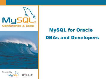
Journal of Technology Research Volume 6 – December, 2014It is important to note that the separation of the vote record, containing the selectedcandidate, from the ballot (member position) is necessary in order to maintain voting privacy.In a real world situation, the above problem statement would usually be followed byadditional inquires, discussion and analysis. In this case, it is assumed that all the necessaryinformation is contained in the above statement.It is interesting to mention that students, taking the author’s DBMS classes, attempted tosolve the above problem in many different ways. Some students followed the analysis guidelinesand developed EER diagrams as recommended. A few students tried to develop prototypesolutions in Excel. Other students went even straight to MySQL system’s shell and developed aphysical database, using SQL. Providing a detail instruction for a full cycle database design andimplementation process goes beyond capacity of this paper. However, a complete, step by step,instruction can be retrieved from Google Drive and from a mirror URL (Letkowski, 2014). Thisinstruction will be maintained to keep it up to date with updated software (MySQL).Step 1: AnalysisAs mentioned, the initial analysis of the problem statement should focus on identifyingentities (entity types). Good nominees for the entities are sets of objects that are critical to thedatabase’s objective: to facilitate an on-line election of the leaders (officers) of an organization.Formulating a condensed problem description, consisting of short statements incorporatingrelevant objects is helpful. Such statements will also help capture relationship between theobjects. For example: The organization has members. Some of the members (candidates) intend to serve as officers. The officers are elected by the members. The candidates receive votes.From this brief description one can extract two core entities: Member and Office. EntityMember consists of all the organization’s members. Entity Office includes all the leadershippositions of the organization (‘President’, ‘Vice-president for Membership’,‘Vice-president at Large’, ‘Treasurer’, etc.).The analysis tasks cannot be separated from the model development tasks. As newentities and relationships are added to the data model, other entities, attributes and relationshipsmay emerge. At this point, having identified the basic entities, one can start developing themodel.Step 2: Model BuildingSince MySQL Workbench (MW) treats an entity as a table, these two terms will be usedinterchangeably. Adding an entity to a MW model is simple: Start MW. Create a new EER diagram. Use the Table tool to add tables (entities) to the diagram (Figure 1). Define all attributes (Figure 2).From the statement “The officers are elected by the members.” one can learn that there isa Many-to-Many relationship between entities Member and Office:Doing database design, page 6
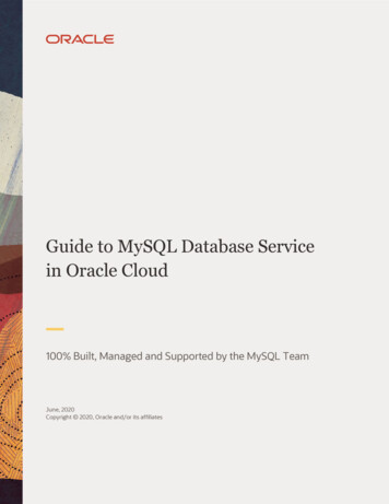
Journal of Technology Research Volume 6 – December, 2014 Member (*) – elects – (*) Office .Each officer (an instance of entity Office) is elected by many members and eachmember (an instance of entity Member) electa many officers. When this relationship isapplied (Figure 3), using the Many-to-Many (n:m) tool, MW inserts an associative entity(Member has Office) as shown in Figure 4. This entity gets foreign keys from the primarykeys of the base entities (Member and Office). Combined together, they also serve acomposite primary key for this entity (table). It seems reasonable to change the default name ofthis new entity to, for example, Ballot and make the participation in its relationships optional.Ballots (instances of entity Ballot) serve as transactions so it makes sense to add the exacttime when members pick up their ballots. In MySQL Workbench, elements of the EER diagramcan be edited either by double-clicking or selecting them and pressing Ctrl E . Figure 5 showshow the Ballot entity is incorporated into the model.From the statement “Some of the members intend to serve as officers.” one can learn that there isanother relationship between Member and Office. A [candidate] member is running forone office and a given office has many [candidate] members. This is a Many-toOne relationship: Member (1:*) – is running for – (0.1) Office ,with entity Office having an optional participation in this relationship (a given member maybut does not to have be running for any office). Because of this optional participation,implementing this relationship directly with in entity Member would produce a foreign key,having null values for members not being candidates. It would be an odd solution that, aspointed out by (Date 2009, p. 332), does not naturally occur in the real world. A more elegantsolution is to separate candidates from members and to have a direct relationship betweencandidates and positions (offices). Thus a Candidate entity is introduced. Sinceeach candidate is a member, the relationship between entity Candidate and entityMember becomes hierarchical. Unfortunately, MySQL Workbench does not directly supportsuch a relationship. It does, however, support a One-to-One relation which can be applied tothe Member – Candidate relationship, assuming an optional participation of entityCandidate: Candidate (0.1) – is a – (1) Member .This relationship states that a candidate is a member and a member may but does not haveto be a candidate. It is added to the diagram using the identifying, One-to-One(1:1) tool. Entity Candidate inherits its primary key from entity Member. This key alsoserves as a foreign key. Once entity Candidate is added to the model, its relationship withentity Office can be formulated, using the non-identifying, One-to-Many (1:n)tool: Candidate (*) – runs for – (1) Office .The primary key of entity Office generates a foreign key in entity Candidate. Figure 6shows the model with entity Candidate and its relationships.In the election model, ballots can’t exist without the related members andoffices. Each candidate requires existence of its related member. Thus relationshipsDoing database design, page 7
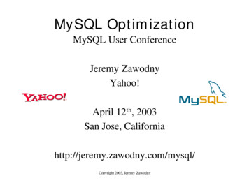
Journal of Technology Research Volume 6 – December, 2014Member – Ballot, Ballot – Office and Member - Candidate are allidentifying relationships. On the other hand, a candidate is uniquely identified just byits member ID (mid) and different candidates may have the same office ID (oid). ThusCandidate – Office is a non-identifying relationship.The final statement of the brief description (“The candidates receive votes.”)suggests that the model should also include a Vote entity. Logically, instances of this entityshould be associated with ballots and candidates. However, because of the privacyrequirement a relationship between Vote and Ballot is not allowed. Thus entity Vote isadded to the model being related only to entity Candidate: Candidate (1) – gets – (*) Vote .Entity Vote has its own primary key (a unique signature) which is why it is connected to entityCandidate, using the non-identifying One-to-Many (1:n) relationship. Through thisrelationship, entity Vote acquires its foreign key that is spawn by the primary key of entityCandidate. In this relationship, entity Vote has optional participation (it is possible thatsome candidates will not receive any votes). The final version of the model is shown inFigure 6.Step 3: Schema GenerationThrough menu options “Database Forward Engineer ” or “File Export ForwardEngineer SQL CREATE Script ” MW runs a procedure that takes the EER model andtransforms it into an SQL script. Notice that the former executes the generated script, thus alsocreating a physical database. The latter only generates the script that can be executed at someother time. The following SQL code is based on the generated script:DROP SCHEMA IF EXISTS election ;CREATE SCHEMA election ;USE election ;CREATE TABLE Member ( mid INT NOT NULL, firstName VARCHAR(45) NULL, lastName VARCHAR(90) NULL, pass CHAR(12) NULL, email VARCHAR(90) NULL,PRIMARY KEY ( mid ));CREATE TABLE Office ( oid INT NOT NULL, title VARCHAR(45) NULL,PRIMARY KEY ( oid ));CREATE TABLE Ballot ( mid INT NOT NULL, oid INT NOT NULL, ballotPickupTime DATETIME NULL,PRIMARY KEY ( mid , oid ),FOREIGN KEY ( mid ) REFERENCES Member ( mid ),FOREIGN KEY ( oid ) REFERENCES Office ( oid ));CREATE TABLE Candidate (Doing database design, page 8
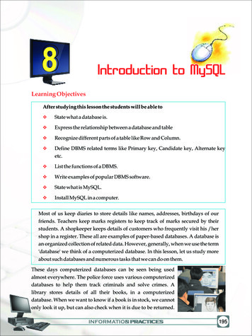
Journal of Technology Research Volume 6 – December, 2014 mid INT NOT NULL, oid INT NOT NULL,PRIMARY KEY ( mid ),FOREIGN KEY ( mid ) REFERENCES Member ( mid ),FOREIGN KEY ( oid ) REFERENCES Office ( oid ));CREATE TABLE Vote ( vid INT NOT NULL, mid INT NOT NULL,PRIMARY KEY ( vid ),FOREIGN KEY ( mid ) REFERENCES Candidate ( mid ));It is interesting to note that this SQL script is 100% compatible with Microsoft Access whereeach table is to be created separately. Access converts the char and varchar data types to itsproprietary text type. In MySQL, this script can be executed in a batch mode.CASE 2: REVERSE ENGINEERINGERDs are excellent documentation resources and indispensable SQL development tools.There are situations where physical databases already exist but their logical data models are lostor have never been developed. In such situations, MySQL Workbench can recreate the modelsusing its reverse software engineering procedures. All it takes is to start a new instance ofMySQL Workbench and select option “Models Create EER Model from Database”. MW willthen provide a series of dialog boxes, letting the user to connect to the server and select thedatabase. Figure 8 shows an EER diagram re-created from the election database. The initialresult is not perfect. It requires a few minimal touch-ups. For example, the re-generatedassociation between Candidate and Member is shown and Many-to-One. It is supposed tobe One-to-One with optional participation of entity Candidate: Candidate (0.1) – is a – (1) Member .In addition some of the optional cardinality constraints are not properly re-generated (optionalparticipation of entities Ballot and Vote). They should eventually be fixed according to theoriginal solution: Ballot (0.*) – filled by – (1) Member , Ballot (0.*) – filled for – (1) Office , Candidate (1) – gets – (0.*) Vote .A similar, but less detailed, diagram is produced by Microsoft Access (Figure 9). A closerinspection reveals that Access properly identifies relationship Member – Candidate as Oneto-One. However the diagram shows this relationship as One-Many (1 - ).CONCLUSIONSRelational databases are complex data structures with solid formal background and lots ofmature development and exploration tools. When dealing with just a few entities, an experiencedarchitect, while mentally visualizing the database structure, may be able to create the databasedirectly using SQL based table definitions. When designing a database in a team setting,especially when the members of the team have diversified backgrounds, utilizing graphical toolsis imperative. Subject-matter experts, participating in the design process and having limiteddatabase expertise, generally prefer working with graphical design tools. MySQL WorkbenchDoing database design, page 9
Journal of Technology Research Volume 6 – December, 2014can satisfy the most demanding database designers, providing excellent graphical andtechnological tools. It should be given more consideration in teaching introductory databasecourses as it provides complete support for the round-trip database engineering.REFERENCESDate, C. J. (2004). An Introduction to Database Systems. Boston: Pearson / Addison Wesley.Date, C. J. (2009). SQL and Relational Theory. How to Write Accurate SQL Code. Cambridge:O’Reilly.Connolly, T., Begg, C. (2005). Database Systems. A practical Approach to Design,Implementation, and Management. Reading: Pearson / Addison Wesley.Elmasri, R., Navathe, S. B. (2004). Fundamentals of Database Systems. Boston: Pearson /Addison Wesley.Wikipedia-MySQLW (2014). MySQL Workbench.Retrieved from: https://en.wikipedia.org/wiki/MySQL WorkbenchLetkowski, J. J. (2014), Database Design with MySQL Workbench. elYsQSYpMqzuU09OAQOmKPS3zt9yGZ9XO-sRs/edit?usp sharing. Mirror URL:http://quantlabs.com/db/design/withMySQL Workbench.pdf.Doing database design, page 10
Journal of Technology Research Volume 6 – December, 2014APPENDIXFigure 1 The base entities, Member and Office, placed on the model panel, using the table tool.Figure 2 The attributes of the Member entity. Attribute mid is the primary key.Doing database design, page 11
Journal of Technology Research Volume 6 – December, 2014Figure 3 Using the Many-to-Many relationship tool, the entities Member and Office areconnected in order to define the relationship between them.Figure 4 MySQL Workbench inserts an associative entity (Member has Office), resulting fromthe Many-to-Many relationship.Doing database design, page 12
Journal of Technology Research Volume 6 – December, 2014Figure 5 The associative entity, Ballot, and its relationships are edited to represent facts aboutthe members completing their ballots for the positions (offices) they vote for. Theentity’s participation in this relationship is set to optional.Figure 6 Entity Candidate and its relationships extend the model.Doing database design, page 13
Journal of Technology Research Volume 6 – December, 2014Figure 7 With the Vote entity and its relationship, the model is complete.Figure 8 The EER model reverse-engineered from the database.Doing database design, page 14
Journal of Technology Research Volume 6 – December, 2014Figure 9 A Relationship diagram produced by Microsoft Access.Doing database design, page 15
Doing database design, page 1 Doing database design with MySQL Jerzy Letkowski Western New England University ABSTRACT Most of the database textbooks, targeting database design and implementation for information systems curricula support the big datab