Transcription
International Journal of Scientific & Engineering Research Volume 12, Issue 9, September-2021ISSN 2229-5518180The Design of Fluid Holding Tank Control SystemUsing Programmable Logic Controller (PLC)Eric T. Jones, Aaron Mineen & Decontee Q. WessehElectrical & instrumentation Engineer @ Conex Petroleum Refinery, Freeport, Monrovia, LiberiaElectrical Engineer @ NRECA International, Mamba Point, Monrovia, LiberiaOperations Manager @ Liberia Electricity Corp. Hydropower Plant, Mount Coffee, LiberiaEmail: e.jones2g15@gmail.comEmail: amineen64@gmail.comEmail: royaldex1@gmail.comAbstract— In the midst of technological advancements, there are a number of industries in Liberia that uses primitive techniques in controlling thedaily operation of fluid storage tanks. These industries such as the Liberia Petroleum Refinery Corporation (LPRC), etc, still use the rudimentary methods of allowing personnel to carry on the daily operations of storage tanks during productions, which place the personnel involved into hazardous situation and also lead to inefficient productivity. However, to avoid workers physical interaction with these holding tanks that pose danger to their lives, industries operating in Liberia, need to employ an automatic control system that carries out the daily operations of these tanks without workers physical interaction with them. This laborious and risky task can be performed using automatic control system that both monitors the fluid level in the tanks duringpumping and stops the pump when the desired fluid level has been achieved.In this project we are concern with the one that provide level measurement capability. A flow control valve serving as a double acting valve is controlledautomatically to respond to changes in pump pressure to fully open or partially open the valve to a desire flow percentage, regulating the flow rate of thefluid. Also, the pump response to changes in the fluid level in tank to either start filling if level is at it set low level or stop filling if level reaches safe fillingheight. The main components used in this project are: Programmable Logic Controller (PLC) and accessories, Level sensors, Indicators, DC source, andholding tank unit comprising of tank, pump and control valve.It has been an achieving pleasure to work on practice & progress of PLC based fluid holding tank control system because it provides information aboutmany topics relevant to control system or equipment automation. The great advantage of PLC based fluid holding tank control system is with maximumaccuracy. Also the system has higher reliability, small space requirements, reduced cost and able to work as friendly with environment. This project isapplicable in Fluid level control in sewage system; Fluid level control in boiler system; petroleum products level control in refinery, generator and automotive engine; chemical level control in washing plant; homely use water tank level and water treatment plant .Index Terms — holding tank, solenoid, control valve, coil, Programmable Logic Controller, contacts, sensors—————————— ——————————1 INTRODUCTION1.1 IntroductionTechnological advances in recent years have resulted in thedevelopment of the programmable logic controllers (PLC) anda consequential revolution of control engineering. PLC is aspecial form of microprocessor-based controller which includes programmable memory to store instructions and toimplement functions such as logic, sequencing, timing, counting and arithmetic operations. The Programmable Logic Controller (PLC) is widely used in different plants like power generation, boiler, level control, chemical plants, paper plant, andwater treatment plant, food processing plant, washing machine control, and control of machinery on factory assemblylines to expand and enhance productivity. In fact the PLC isused in every aspect of the industry where automation of typical industrial electromechanical processes is required (W. Bolton, 2006). This project presents methods of designing an automatic control system that enables the pumping of fluid intoa storage tank, monitors the fluid level in the tank duringpumping, stops the pump when the fluid has reached desiredlevel, and enables the reverse flow of the fluid from the tankusing programmable controllers.1.2 Background of ProjectThe advancement of the PLC began in 1968 with General Motors Corporation. The primary goal was to eliminate the highcost associated with inflexible relay-controlled systems. Thespecifications of the first PLC designed by General Motorsrequired a solid-state system with computer flexibility able to(1) survive in industrial environment, (2) be easily programmed and maintained by plant engineers and technicians,and (3) be reusable. (Karl-Henz John, et al, 2001).Such control system would reduce machine downtime andprovides expandability for the future. The product implementation to satisfy General Motors’ specifications was underwayin 1968; and by 1969, the programmable controller had its firstproducts. These early controllers met the original specifications and opened the door to the development of a new control technology. The first PLCs offered relay functionality, thusreplacing the original hardwired relay logic, which used electrically operated devices to mechanically switch electrical circuits. They met the requirements of modularity, expandability, programmability, and ease of use in an industrial environment. The controllers were easily installed, used lessspace, and were reusable and were programmed using ladderdiagrams.In a short period, programmable controller use started toIJSER 2021http://www.ijser.org
International Journal of Scientific & Engineering Research Volume 12, Issue 9, September-2021ISSN 2229-5518spread to other industries. By 1971, through the HydromanticDivision of the General Motors Corporation, PLCs were beingused to provide relay replacement as the first steps towardcontrol automation in other industries, such as food and beverage, metals, manufacturing, and pulp and paper. The firstprogrammable controllers were more or less just relay replacers. Their primary function was to perform the sequentialoperations that were previously implemented with relays.These operations included ON/OFF control of machines andprocesses that required repetitive operations, such as transferlines and grinding and boring machines. However, these programmable controllers were vast improvement over the relays. They were easily installed, used considerably less spaceand energy, had diagnostic indicators that aided troubleshooting, and unlike relays, were reusable if a project was scrapped.Although PLC functions, such as speed of operation, types ofinterfaces, and data-processing capabilities, have improvedthroughout the years, their specifications still hold to the designers’ original intentions—they are simple to use and easy tomaintain.Many technological advances in the programmable controllerindustry continue today. These advances not only affect programmable controller design but also the philosophical approach to control system architecture. These advances haveled to the automation of major industrial plants that havehelped shape the modern world by changing the ways of processing, storing and distributing fluid in plants such as watertreatment plant and oil processing and distribution plant.PLCs can be used to control the flow rate of fluid in transmission and distribution pipes by automatically closing and opening valves.They can also be used to monitor sensors on a holding tank inorder to determine the fluid level in the tanks. By controllingthe starter circuit of a pump, PLCs can be used to control theon and off status of an entire pumping system. As statedabove, the PLC has brought lots of advancements to controlengineering and this project highlights its usefulness in theindustry. (L.A & E.A Bryan, 1997).1.3 Problem StatementFluid treatment and processing plants in Liberia such as theLiberia Petroleum Refinery Corporation (LPRC) still use therudimentary methods of allowing workers to climb on verylarge storage tanks to monitor product level as it is beingpumped from the ship to the tanks and then send communication to the team on the ship’s deck to manually stop the pumpwhen the product in the tank has reached the desired level.This laborious and risky task can be performed using automatic control system that both monitors the product level in thetanks during pumping and stops the pump when the desiredoil level has been achieved.This same control system could be used in water treatmentplants to control the pumping of water in storage tanks andthe distribution of the water to the various networks. This project presents a design of such a control system using PLC thatenables the pumping of fluid in a holding tank, monitors thefluid level in the tank and automatically stops the pump whenthe preset fluid level has been reached.1811.4 Objective of ProjectThe major objective of the project is to provide a viable engineering alternative to the laborious and sometimes risky taskof using human to monitor fluid level in large holding tanks,to provide alternative to the manual switching ON/OFF ofpumps in treatment and processing plants, and to avoid themanual opening and closing of certain strategic valves intreatment and processing plants. To achieve these dedicatetasks, we have designed a control system using programmablecontrollers to automatically switch ON/OFF the pump as required. A fluid level controller sensor is employed along withan indicator to detect and monitor fluid level in the tank andto feed the results to the PLC which then compares the resultto the written instructions in its memory and then perform therequired task.1.5 Overview of fluid holding tank control systemFluid holding tank control system is a control program designusing PLC. Its consist of level sensors that are used to monitorthe water level in the tank and transmit the level read to PLCand based on the level the PLC sends signal to the flow controlvalve and pump so as to control or stop the flow of fluid toholding tank in order to avoid overflow of fluid which resultsinto wastage or possibly unavailability of fluid in case ofemergency. The system pumping formed an integral part ofthe tank level control. At a pre-set maximum level, a controlsensor will turn the pump OFF and the tank will automaticallystop filling and then starts to distribute fluid to desire locations. As soon as the tank drains to its set minimum level, automatically the control will turn ON the pump to start fillingthe tank again. The instrumentation measurement of level isbased on two major classifications which include Point leveland Continuous level measurements. For the point levelmeasurement it indicates fluid presence or absence in the tankat a certain point while continuous level measurement indicates the level of the fluid in the tank over a full range of possible measurements.Some water level controls enable water level measurementcapability and some do not, such as solenoid valves. In thisproject we are concern with the one that provide level measurement capability. A flow control valve serving as a doubleacting valve is controlled automatically to respond to changesin pump pressure to fully open or partially open the valve to adesire flow percentage, regulating the flow rate of the fluid.Also, the pump responds to changes in the fluid level in tankto either start filling if level is at it set low level or stop filling iflevel reaches high level.1.6 Limitations of ProjectThis automatic control system design project like every otherproject has some limitations. The major limitation is with thesoftware we used to simulate our design. The animation usedby Multisim to portray the holding tank has only one pipethrough which the fluid is pumped to and from the tank.1.7 Organization and apparatus of the projectIJSER 2021http://www.ijser.org
International Journal of Scientific & Engineering Research Volume 12, Issue 9, September-2021ISSN 2229-5518The main components used in this project are:1. Programmable Logic Controller (PLC) and accessories2. Level sensors,3. Indicators4. DC source5. Holding tank unit.182ries out the corrective action. For instant, when manually controlling a fluid holding tank, the operator physically adjust thepump power switch(ON) to start the pumping of fluid intoholding tank and again physically adjust the powerswitch(OFF) to stop the pumping of fluid as soon as the fluidstarts to overflow. This type of control is very primitive andcauses wastage of fluid therefore it is not advisable to be usein the midst of technological advancement.2 LITERATURE REVIEW2.2.1.2 Automatic control2.1. IntroductionThis chapter basically discusses the review of the project inaccordance to fluid holding tank control system that is widelyused in industries and residential areas. Summary of commonly used fluid holding tank controller technologies are also discussed in this chapter based on their description, advantagesand disadvantages.Fluid holding tank control technology such as Programmablelogic controller is very important to discuss when designingthe control program of fluid holding tank. This chapter alsodiscusses the fluid level controller with regard to the type offluid, shape of the tank and the tank capacity.And finally, the chapter shows the functional description, operation and circuit diagram of the holding tank control program designed using PLC. This is important to compare theuse of PLC or Conventional control in controlling the holdingtank of a fluid.2.2. Control system of fluid holding tankFluid holding tank is very important in the distribution of fluid in industries and residential areas depending on the kind offluid one is considering. Since fluid when wasted are unable tobe re-gathered, therefore, it is important to employ a controlsystem, manual or automatic in order to monitor the flow offluid in and out of the tank so as to avoid wastage or perhapsunavailability of fluid in case of emergency.In the past, human physically controlled the operation of holding tank. However, quite recently the use of electrical controlbased on relays has been used to control operation of holdingtanks. The switching on and off of power without a mechanical switch is performed by relays. Additionally, the development of low cost computer has brought the most recent revolution. The Programmable Logic Controller (PLC) is widelyused in different plants like power generation, boiler, levelcontrol, chemical plants, textiles mills, paper plant, watertreatment plant, petroleum refinery and food processing plant.Most of the present science and technology of the control system is based on microcontroller and PLC. (Woodward Governor).2.2.1Type of Control2.2.1.1 Manual ControlManual control requires the physical interference of operatorwith the operation process of the system. That is the operatoroperate the process to a desire condition, then the system car-For an automatic control, desire conditions or instructions areprocessed into the system by some logical software application design using programmable logic controller. Based on theinstructions the instruments carry out the corrective actionsautomatically without human physical interference. Also, anautomatic control system is developed using electrical controlbased on relays, contactors and timers.Since the advancement of technology resulting to the development of low cost computer, automatic control system design using PLC is much preferable than the ones design usingelectrical control based on relays, contactors and timers because PLC program and electronic communication lines unlikethe electrical control, does not require hard-wired control forits interconnections but instead uses common coded instructions design in control software application that are easy to becorrected and modified. Automatic control increases production, Improve quality, greater production uniformity, uses lessraw materials and manpower. For these reasons automaticcontrol is used most widely now a day in industries. (Rojiha,C., 2013).2.3 Importance and usage of fluid holding tankFluid holding tanks are often the most visible and expensivecomponent of fluid distribution system. They are used tostored wide range of fluid including drinking water, petroleum products, sewage, chemicals etc. Some of the fluid are keptin holding tanks to be use in the future in case of emergencywhile other fluid such as sewage and chemical are kept inholding tanks to avoid contaminating the environment. Thefluid is safely disposed of.Holding tanks are very important because they provide storage for treated drinking water before it is distributed to endusers; provide storage for refined petroleum products beforethey are distributed; and provide storage for treated sewagebefore they are sent into the public sewage line. Holding tanksalso accommodate the flows of fluid necessary for emergencies such as firefighting and provide equalize pumping ratesfor the supply and demand of fluid. It is also used to supplyfluid during emergencies such as loss of pumping capacity asa result of power outage. These plus many more make holdingtanks very important in the distribution of fluid.2.4 Fluid level indicator and controllerThe control or management of fluid level in holding tanks re-IJSER 2021http://www.ijser.org
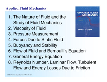
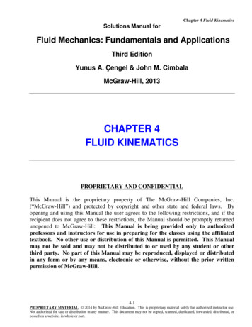
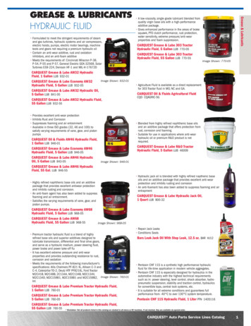
International Journal of Scientific & Engineering Research Volume 12, Issue 9, September-2021ISSN 2229-5518duces power consumption and as well as overflowing of fluid.It also indicates the amount of fluid entering or leaving theholding tanks.The lack of adequate and integrated fluid management has ledto the unsustainable availability of fluid resource. In the Lastfew decades several monitoring system integrated with fluidlevel detection have become accepted. Fluid level control issimply to start the feed pump at low level and allow it to rununtil a higher fluid level is reached in the holding tank.This simple method of level control is not properly supportedfor adequate controlling system. However, fluid level sensorwhich provide visual multi-level as well as continuous levelindication, are widely used for monitoring fluid level in holding tanks now a days.Fluid level monitoring and controlling system are concentrated with some basic parts which include fluid level indicator,fluid level sensor, fluid pump controlling system etc. Whenthe power is switch on and the motor circuit is energized, thefluid pump controlling system gets on and starts to pump fluid into holding tank. As soon as the fluid level sensor sensesfluid in the holding tank, the level indicator which is oftenLED light indicator as shown in figure 2.1, comes on to indicate the fluid level in the tank and then the sensor also, transmit the level of the fluid to PLC through it input module. ThePLC through its output module sends a command to thepump to either start or stop the pumping of fluid into theholding tanks based on the low or high level of the tank. Forthis project a bar graph LED light indicator is used to indicatethe fluid level. Each light on the graph comes on upon thepumping or draining of five liters.183control equipment in an industrial facility. The kinds ofequipment that PLC controls varied as per industrial facilitiesthemselves. Conveyor systems, food processing machinery,auto assembly lines, fluid holding tank system etc. are example of some equipment that are controlled by PLC. Formal inan industrial control system, all control devices are wired directly to each other according to how the system is supposedto operate.However, the PLC replaces the wiring between the devices.Thus, instead of being wired directly to each other, all equipment are wired to the PLC. Then, the control program insidethe PLC provides the “wiring” connection between the devices. The control program is the computer program stored in thePLC’s memory that tells the PLC what’s supposed to be goingon in the system. The use of a PLC to provide the wiring connections between system devices is called soft wiring.A programmable logic controller (PLC), also referred to as aprogrammable controller, is the name given to a type of computer commonly used in commercial and industrial controlapplications. Based on the tasks performed by PLCs and thehardware and software they require performing these tasks,they are different from ordinary office computers. While thespecific applications vary widely, all PLC monitor inputs andother variable values, make decisions based on a stored program, and control outputs to automate a process or machine.(Amunrud Alana., 2002).2.5 Conventional Control System and ProgrammableLogic ControllerBoth Conventional control System and PLC are automatic control systems. They only provide instructions to the instrumentthrough electromechanical relays and timers if it is conventional control or through control programmable logic designusing PLC.These instructions are translated automatically by the instrument into its corrective action without human physical intervention. However, since the advancement of technology, theuse of conventional control system has been widely replacedby PLC because unlike conventional control which uses electromechanical contactor, relays, timers, counters etc. that required hard-wired connections, PLC basically operates by examining the input signal connected from the process and carried out logic instructions on these input signal and then itproduces output to a drive process, equipment, or machineryvia less intermediate circuitry relay.PLC are easy to program, highly reliable, and easy to maintenance unlike Conventional control which require rewiring ofentire system hard-wired if any changed is required in theprocess.(Middle Brooks, et al., 1977).2.5.1Figure2.1: A topology of a PLC system.U1Figure2.2: A typical LED light bar graph used in this project asfluid level indicator.DCD BA RGRA PH12 VBasic of Programmable Logic ControllerA Programmable Logic Controller is a mini computer used to2.5.2The importance of PLC to this projectIJSER 2021http://www.ijser.org
International Journal of Scientific & Engineering Research Volume 12, Issue 9, September-2021ISSN 2229-5518The development of low cost computer has brought the mostrecent revolution. Programmable Logic Controller (PLC) iswidely used in different plants like power generation, boiler,level control, chemical plants, textiles mills, paper plant, watertreatment plant and food processing plant nowadays. PLC isone of those present days’ technologies that control system isbased on.The advance of the PLC began in the 1970s and has becomethe most common choice for manufacturing controls. PLC hasbeen gaining popularity on the factory floor and will probablyremain predominant for some time to come. Most of this isbecause of the advantages they offer. The PLC is not only capable of performing the same tasks as hard-wired control, butare also capable of many more complex applications.In addition, the PLC program and electronic communicationlines replace much of the interconnecting wires required byhard-wired control. Therefore, hard wiring, though still required to connect field devices, is less intensive. This alsomakes correcting errors and modifying the application easier.2.5.3Functional description of PLC.PLC is actually an industrial microcontroller system wherehardware and software specifically suited to industrial environment is designed. When considering PLC, one need to paykeen attention to the input and output blocks because in themthere is protection needed in isolating a CPU blocks fromdamaging influences that industrial environment can bring toa CPU via input lines. Computer used for writing a program isreferred to as a Program unit.When using PLC to design a control system, one uses a simpleform of high level language like ladder diagram, instructioncode etc. to entered the control program into the PLC. Theinput device such as switch, push button, sensor and outputdevice such as motor, relays, valves, lamps etc. are connectedto PLC.The operator then enters a sequence of instructions into thememory of the PLC. The controller then monitors the inputsand outputs according to these programs and carries out thecontrol rules for which it has been programmed.Power supply- electrical supply is used in bringing electricalenergy to the central processing unit. Most PLC controllerswork either at 12VDC, 24 VDC or 220 VAC. In some system,PLCs are electrically supply as a separate module. Those areusually bigger PLCs.In this project, a simple form of high level language calledladder diagram is used to enter the control program into thePLC.2.5.4PLC components and operationBasically the input and output modules or points, Central Processing Unit (CPU) comprising of the memory, program anddata, and a programming device are elements a PLC consistof. PLC uses a type of input modules or points depending upon the types of input devices being used. If the input device isa digital or discrete input device which is either on or off, an184input module that respond to it is used.Also if it is an analog signal input device which represent machine or process conditions as a range of voltage or currentvalues, a corresponding input modules or points that respondto analog signal is used.The input circuitry of a PLC primary responsibility is to convert the signal provided by these various sensors and switchesinto some logical signal that can be used by the CPU.2.5.4.1 Basic PLC OperationBasically a PLC operates in such a way that the CPU evaluatesthe status of inputs, outputs, and other variables as it executesa stored program. The CPU then sends signals to update thestatus of outputs. Output modules convert control signalsfrom the CPU into digital or analog values that can be used tocontrol various output devices.The programming device is used to enter or change the PLC’sprogram or to monitor or change stored values. Once entered,the program and associated variables are stored in the CPU. Inaddition to these basic elements, a PLC system may also incorporate an operator interface device to simplify monitoringof the machine or process. (Moore, et al., 2010).2.5.4.2 The Central Processing Unit (CPU)The CPU is an essential component of a Programmable Controller. It is considered as the “brains” of a programmable controller because it perform all of the logical work of a PLC including retrieving, decoding, as storage and processing of information. It also executes the control program stored in thePLC’s memory. The function of a PLC’s CPU is no differentfrom that of a regular computer’s CPU except that it uses special instructions and coding to perform its functions.The CPU of a PLC consists of three main parts which includethe processor, the memory system, and the power supply. Theprocessor codes, decodes, and computes data, the memorysystem stores both the control program and data from theequipment connected to the PLC and lastly the power supplyprovides the PLC with the voltage and current it needs to operate.2.5.4.3 The Control programThe control program is a software program in the PLC’smemory. It writes the control in a programmable controller.The control program is developed or designed by the user orthe system designer .It is made up of things called instructionswhich are, in essence, little computer codes that make the inputs and outputs do what the user or designer want in orderto get the result he or she needs. Instructions or codes (addand subtract data, time and count events, compare information, etc.) may vary depending on what the user or designer want the PLC to do.All you have to do is program the instructions in the properorder and make sure that they are telling the right deviceswhat to do and what not to do you have a PLC-controlledsystem. If you want the system to act differently, just changeIJSER 2021http://www.ijser.org
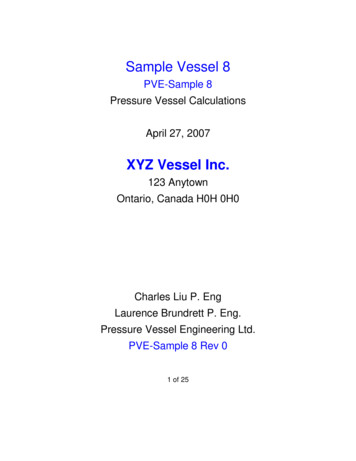
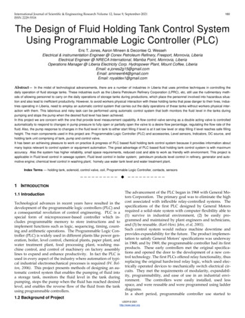
International Journal of Scientific & Engineering Research Volume 12, Issue 9, September-2021ISSN 2229-5518the instructions in the control program.What make each type of PLC unique is that PLC offer differentkinds of instructions depending on its type. However, all PLCuse two basic types of instructions: Contacts and Coils,185Figure 2.3: An example of contacts found in ladder diagram. X1is a normally closed input contact and X2 is a normally openedrelay contact.X32.5.4.3.1 Contacts2.5 VX2Contacts are instructions that refer to the input conditions ofthe control program that is, the information supplied by theinput field devices. Each contact in the control program monitors a certain field device. The contact waits for the input to dosomething in particular (e.g., turn on, turn off, etc.—this alldepends on what type of contact it is). Then, the contact tellsthe PLC’s control program, “The input device just did whatit’s supposed to do. You’d better check to see if this is supposed to affect any of the output devices. An example of contacts found in ladder diagram is found in figure 2.2.M1V1J1M1CR12 VKey AFigure 2.4a.: shows the initial stage where the switchis not yet trigger to energize the coil.X3X22.5.4.3.2 Coils2.5 VM1Coils are instructions that refer to the outputs of the controlprogram that is, to what each particular output device is supposed to do in the system. Like a contact, each coil also monitors a certain field device. However, unlike a contact, whichmonitors the field device and then tells the PLC what to do, acoil monitors the PLC control program and then tells the fielddevice what to do. It tells the output device, “Hey, the PLCjust told me that the switch turned on. That means that you’resupposed to turn on now. So let’s go!”Example- Let’s talk again about that soaped-up switching circuit, in which a wall switch and an overhead light are connected to a PLC. Let’s say that Turning on the switch is supposed to turn on the light.In this situation,
development of the programmable logic controllers (PLC) and a consequential revolution of control engineering. PLC is a special form of microprocessor-based controller which in-cludes programmable memory to store instructions and to implement functions such as logic, sequencing, timing, count-ing and arithmetic operations.