Transcription
POLISHINGOF ASSABMOULD STEEL
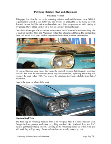
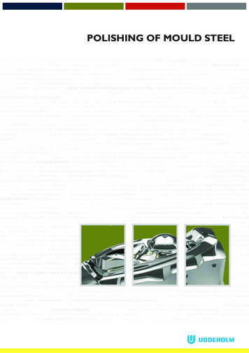
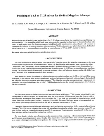
Why strive for ahigh surface finish?Plastic and metallic components aremanufactured with various surfacefinishes all from shiny and glossy tofunctional surfaces of differentappearances. In this brochure wewill inform about the factors thathave the biggest impact on thepolishability of tool steel and giverecommendations on how to obtainthe required surface finish onmoulds, dies, punches and metalliccomponents/parts.Depending on the application andrequirements we can distinguishbetween two types of surfacefinishing methods:high gloss polishingand functional polishing.HIGH GLOSS POLISHINGTools for plastic moulding do requirea high surface finish especiallywhen extreme transparency and/or high gloss are aimed for. In suchcases it is of utmost importanceto choose a proper tool materialand establish a suitable surfacepreparation technique. To achievea reflective surface with mirrorfinish the preparation process mustinvolve several grinding and diamondpolishing steps and these have tobe performed in a clean workplace.The use of proper working toolsfacilitates the process a lot.High surface finish reduces the riskof local corrosion and fracture orcracking due to temporary overloading or pure fatigue.The tool surface finish may alsohave an impact on productivity asin the case of injection moulding.Here, the release forces of theplastic com-ponent from the toolsteel surface are dependant on theadhesion properties of the polymerto the mould surface. An improvedsmoothness of the tool surface maylead to higher release forces andeventually to sticking phenomena,which partly can be overcome byan optimal choice of tool steel andpreparation strategy.FUNCTIONAL POLISHINGMost cold work applications donot need high gloss polished toolsurfaces, but it is always advantageousto create functional surfaces fora prolonged tool life. In formingoperations where lubricants areinvolved a preparation strategymay consist of removing largerpeak formations on the surface andpreserving a controlled depth ofvalleys as lubrication pockets, whichCONTENTSthen will contribute to a reducedfriction during forming. However,it is always important to considerthe final tool steel surface quality inrelation to the application.If a high quality surface coating isgoing to be applied, then it is alwaysrecommended to perform high glosspolishing of the tool surface beforethe coating process.THE POLISHER IS EXTREMELYIMPORTANTThe results from the tests that havebeen carried out during the workwith this brochure shows that theskill, experience and technique ofthe polisher plays an extremelyimportant role in achieving thedesired surface finish.Factors that affectthe surface finishTool steel are used in manyapplication fields within plasticmoulding, cold and hot workingand as engineering components.For proper functionality, but also tominimize the manufacturing cost ofthe tool or component it is vital tospecify the required surface finish onthe engineering drawing. Especiallyin applications of plastic mouldingApplicationWhy strive for a high surface finish2Factors that affect the surface finish2Surface preparation of tool steel4Guidelines5Polishing problems can be solved8Measuring surface roughness and quality9PolishingtechniqueType of polymerType oftool steelSurface qualityPre-preparationof the surfaceHeat treatmentProcess routeFig.1. A number of factors have influence on thesurface finish of the final end product.“ASSAB” and the logo are trademark registered. The information contained herein is based on our present state of knowledge and is intended to providegeneral notes on our products and their uses. Therefore, it should not be construed as a warranty of specific properties of the products described or awarranty for fitness for a particular purpose. Each user of ASSAB products is responsible for making its own determination as to the suitability of ASSABproducts and services.Edition 202007082 POLISHING OF MOULD STEEL
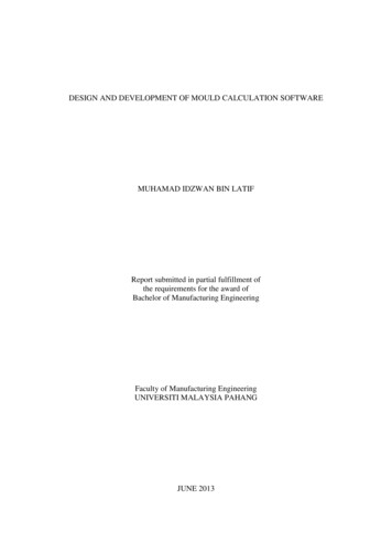
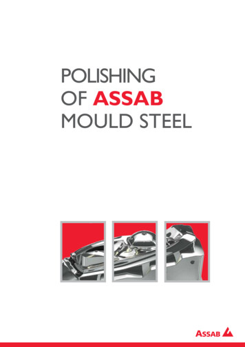
it is important to have access tomaterial data relating to surfacefinish capabilities.However, it should be notedthat the surface finish of the endproduct is not only determinedby the tool steel and the appliedsurface preparation process, butalso the application process itselfhas a big impact on the result.Polymers have different materialcharacteristics at plastic mouldingand this will definitely influence thefinal surface finish, as illustrated inFigures 1 and 2.025050075010001250150017502000µm0500 1000 1500 2000 2500 µmTOOL STEEL QUALITYProcess routes for tool steelTool steel are found in variousalloy combinations to fit usage indifferent application fields. Commonmanufacturing process routes areconventional ingot casting (IC),continuous casting (CC), electroslag remelting (ESR), vacuum arcremelting (VAR) and powdermetallurgy (PM). Remelting processesand PM processes produce materialsof higher homogeneity with a lownon-metallic inclusion content,RecommendationsTo produce highly reflective andglossy surfaces ESR-remelted orPM steel are to be used. However,conventional ingot cast steel cangive a very good surface finish,if both steel manufacturing andpolishing are performed accordingto a good practice.whereas ingot cast materialsnormally have a higher degree ofsegregation patterns and also containmore non-metallic inclusions.Defects in tool steelVarious types of defects emanatingfrom the production process may befound in the steel. During steelmakingnon-metallic inclusions are formedas a result of the deoxidationprocess. Other sources areentrapped exo-genous material fromrefractory in the ladle or at casting.A fast solidification rate is normallybeneficial by giving less time forinclusions and particles to grow andreducing segregation patterns.In the special remelting processessuch as VAR and ESR the cast ingotare remelted under controlledconditions. Non-metallic oxideinclusions are effectively removedfrom the steel and sulphides arereduced substantially via the basicworking slag in the ESR-processTool surface, invertedCONVENTIONAL PROCESS025050075010001250150017502000µm0ASSAB STEEL GRADES:CALMAXASSAB XW-10ASSAB 718 SUPREMENIMAXRAMAX HHASSAB 8407 2MCORRAX500 1000 1500 2000 2500 µmMakrolon AL2647(Medium viscosity)005001000ELECTROSLAG REMELTINGPROCESSASSAB STEEL GRADES:STAVAX ESRMIRRAX ESRMIRRAX 40ASSAB 8407 SUPREMEVIDAR 1 0µmBayblend T45(Low viscosity)Fig 2. The photos show differently holes/pits on tool surface replicated on theplastic plaque due to different materialcharacteristics in different polymers. Fewerpeaks is detected on the Makrolon plaquewhereas the Bayblend plaque had visiblepeaks all over the surface.POWDER METALLURGYPROCESSASSAB STEEL GRADES:VANADIS 4 EXTRA SUPERCLEANVANADIS 10 SUPERCLEANELMAX SUPERCLEANFig 3. Process routes for tool steel andexample of steel grades produced by thedifferent routes.POLISHING OF MOULD STEEL 3
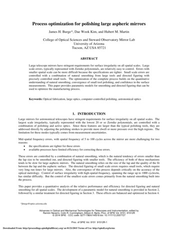
altogether giving tool steel of highcleanliness.The remelting processes direct thecasting structure in such a way thatmacro segregations are drasticallyreduced and a more uniformmicrostructure is created, which isbeneficial from polishing point of view.BadSurface preparationof tool steelThe following four terms arecommonly used when it comes tosurface preparation of tool steel.The essential characteristics of thesemethods are explained below.GrindingThe abrasive particles are firmlybonded to a carrier such as grindingpaper, stones and the discs.Polishability rank54ELST3ATCGOSTEAIN21Good PMESR REMELTED STEELSampleBGlueBackingLowHighDefect content by inclusions and carbidesTotal number of particles per mm2 *(oxides sulphides carbides nitrides)1000100LappingThe abrasive particles are not bondedbut move freely between the carrierand the work piece.10A10.1ESRPMConventional*oxides and sulphides 3µm carbides and nitrides 4µmFig. 4. A low defect content is beneficial frompolishing point of view.Heat treatmentHeat treatment can affectpolishability in many ways.Decarburisation or recar burisationof the surface during heat treatmentcan produce variations in hardness,resulting in polishing difficulties.In order to avoid this it isrecommended that the hardening iscarried out in vacuum furnaces orfurnaces with controlled protectivegas atmosphere or salt baths. It isalso of importance to secure thatthe time at austenitizing temperatureis not too long and the quenchingspeed is not too slow to avoidgrain growth and grain boundaryprecipitations.4 POLISHING OF MOULD STEELBSampleSuspensionMANUFACTURING OFINITIAL SURFACESIt should be emphasised that thegrinding operation forms the basisfor a rapid and successful polishingjob. In grinding, the marks left bythe rough-machining operation areeliminated and a metallically pureand geometrically correct surface isobtained.The finishing preparation steps canbe very time consuming and costly,but can be controlled to a certainextent by a proper manufacturing ofthe initial tool surface. Normally thestarting surface is ground, milled orelectro discharge machined (EDM).Typical initial surface roughnessvalues, as Ra/Rz, are approximately0.5/5 µm for the two former and3/15 µm for an EDM surface.Recent developments in high speedmachining has made it possible toproduce surface finishes betterthan Ra 0.2 µm and by using thelatest tech-niques in EDM the Rafalls below 0.07 µm. After EDMprocessing it is important to removethe heat affec-ted layers by either afine sparking and/or by grinding. If notdoing so crack initiation may appearduring tool use.SupportHINTS FOR GRINDINGPolishingThe abrasives are more or less fixedin the carrier material and will cutand/or plough the surface.OPERATIONGroundMilledHigh speedmachinedEDMSampleASURFACE FINISHRa 0.5 µm Rz 5 µmRa 0.5 µm Rz 5 µmRa 0.2 µm Rz 1.5 µmRa 3.0 µm Rz 15 µmTable 1. Typical initial surface roughness valuesRa and Rz.BBuffingThe abrasive adhere loosely to aflexible carrier (soft disk made ofcloth or hide). This step is consideredamong some polisher to be the lastpolishing step performed in order toobtain a mirror like surface.RecommendationsTo facilitate the finishing steps andto minimize the risk of losingdimensional tolerances of thetool the initial surface finishshould have a roughness value ofmaximumRa / Rz 0.5/5 µm. This willeliminate the need of usingcoarse grinding media in the firstpreparation step.
DESCRIPTION OF ABRASIVESIt is important that the abrasivefulfills requirements with respect to:z hardnessz sharpnessz thermal resistancez chemical stabilityToday, the following five main groupsof synthetic abrasives are used,ful-filling the above requirements togreater or lesser extents.1. Diamond designation SD2. Aluminium oxide designation A(SG)3. Silicon carbide designation C4. Boron carbide designation B4C5. Cubic boron nitride designationAbrasives have different applicationareas, depending on their particularcharacteristics, as shown partially intable 2 below.Table 2.ABRASIVEHARDNESSKNOOPTHERMALSTABILITY INAIR de25001200Baroncarbide29002700CBN470013001. DiamondThe hardest material known, hasa sharp and angular structure. Fastmaterial removal and the bestpossible planarity in combinationwith excellent surface finishes.Distinguish between mono andpolycrystalline diamonds. Monocrystalline are best for lapping, sincethey are round and have many cuttingedges. Natural gives better cuts whilesynthetic are harder, a mix is the bestsince it last longer.2. Aluminium oxide (Al2O3)Is relatively hard and has a sharpangular structure. It is often usedduring the last polishing stepsince it gives excellent and highlyglossy surface finishes. Is relativelyinexpensive.3. Silicon carbide (SiC)Has a needle like blocky structure.Used for rougher surface finishes.z spend more time on the coarsesteps before changing to the finersteps4. Boron carbide (B4C)Is hard and has a blocky crystalstructure. Fast material removalgenerating moderate surface finish.z polishing with diamond compoundfrom 15 µm down to 1 µm grain,use as short time as possible5. Cubic Boron Nitride (CBN)Is produced basically in the sameway as synthetic diamond and is usedwhen grinding hard materials like HSSand hardened high carbide tool steel.RecommendationsMaterial removal in hardenedsteel is more consistent andrepeatable when diamondproducts are used. Precisionhand tools incorporating linearmovement of the working tools,grinding files and polishingstones, give a less troublesomepreparation process. A goodpractice is to work perpendicularto the grooves in all preparationsteps and to verify with opticalexamination that all scratchesfrom the previous step havebeen completely removed. Note,that heavy cold worked materialbeneath the surface needs to beremoved for a perfect end result.GuidelinesNo general recipe exists for alltypes of steel, but the experienceand ability to adjust the polishingtechnique to every single mould andto minor variations in the surfaceis of crucial importance for the endresult. As a general guideline theprocedure for high gloss polishingshown below can be adopted i.e.;z starting from a ground surfacewhere the roughness Ra/Rzshould be maximum 0.5/5 µmz use stones/grinding papers forthe first steps, stepwise grindingto 1200 Meshz always be careful when using softcarriers (felt, brushes, cloths) asthere is a risk of “orange peel”formation on the polished surfaceA reflective surface starts to appearat Ra/Rz approaching 0.1/1 µm, andthe final surface roughness Ra/Rzshould be less than 0.005/0.04 µm fora high gloss polished surface.Fine grindingFine grinding should smooth thesurface before the diamond polishingstage commences.Working tools and compound mediaare built up around different kinds ofabrasives which consists of small andhard particles with sharp edges andirregular shapes.Practical hints for grindingIt should be emphasized that thegrinding operation forms the basis for arapid and successful polishing job.In grinding the marks left by the roughmachining operation are removed and aclean and geometrically correct surface isobtained. The practical hints mentionedbelow apply to both mechanical grindingand manual stoning.z To avoid adding heat and stressinto the surface, do not use toomuch pressure and use plenty ofcoolant.z Use only clean and free-cuttinggrinding tools with soft stonesfor hard surfaces.z It is very important that theworkpiece and the hands of thepolisher are carefully cleanedbetween each change of grainsize. This is done to preventcoarse particles and dust frombeing carried over to the nextgrinding step.POLISHING OF MOULD STEEL 5
z When changing to the next finergrain size, it is recommendedthat the grinding direction bechanged to 45 . Cross-grindingis very simple, but extremelyeffective. It increases stockremoval and it makes it easierto detect scratches from theprevious steps and improve thedimensional accuracy. Figure 5A–C.z Select the sequence ofmovements so that all surfacesegments are processed foran equally long period. With arotating grinding disc there willbe a risk that there will be lessstock removal on the edge thanin the centre of the surface.StandardA45 Practical hints for polishingAbove all, cleanliness in every stepof the polishing operation is ofsuch importance that it cannot beoveremphasized.z Each polishing tool should beused for only one paste gradeand kept in dust proof containers.z Paste should be applied to thepolishing tool in manual polishing,while in machine polishing thepaste should be applied to theworkpiece.z Polishing pressure should beadjusted to the hardness of thepolishing tool and the grade ofpaste. For the finest grain sizes,the pressure should only be theweight of the polishing tool.z Work with hard carriers for asmany steps as possible and workfor as short a period as possiblewith soft carriers.z Polishing should start in the corners, edges and fillets but becareful with sharp corners andedges so they are not roundedoff.z Finish polishing step should,if possible, be carried out inBMillingTurningEDM’ingthe release directional of themoulded part.z With softer carrier the abrasiveis able to penetrate deeper intothe carrier. This will result in thatthe surface will be finer for thesame size of abrasive. See Figure6 below.SoftMediumFeltHardWoodSteelHardened steelFigure 6. The hardness of the carrier affectsthe exposure of the diamond grains and theremoval rate.Typical polishing sequencesThe choice of grinding and polishingsequences are determined by theexperience of the operator andthe equipment he/she has at his/her disposal. The properties of thetool material can also influence thesequence.RoughgrindingRough Grainnumber90 50508080C120120Irregular overlappingFine180180Finegrinding220Rough GrainnumberD320320Fig. 5. Grinding directions.800800FEPAPolishing withdiamond pasteRough Micronsize45µmµm452525151512001200Fig. 7. This figureshows example of how thepolishing sequence can beselected.6 POLISHING OF MOULD STEEL99663311FineFine
Example of different polishingstrategies at high gloss polishingAll polishers have their ownprocedures for high gloss polishing.The data, in Tables 3–5, reflects thatdifferent manual polishing strategiescan be adopted to reach the samefinal surface finish by using rigorousand well proven working procedures.The achieved surface finish is lowerthan Ra 0.01 µmSTEPTECHNIQUETYPE OF TOOLLUBRICATION1Hand-held unitStone320Dielectric oil2Hand-held unitStone400Dielectric oil3Hand-held unitStone600Dielectric oil4Hand-held unitPaper400Dry5Hand-held unitPaper600Dry6Hand-held unitPaper800Dielectric oil7Hand-held unit (linear)Brass 5 x 5 mmDP 9 µmDielectric oil8Hand-held unit (linear)Wood 5 x 5 mmDP 9 µmDielectric oil9Hand-held unit (linear)Wood 5 x 5 mmDP 6 µmPolishing oil10Hand-held unit (rotational)Hard felt 10 mmDP 3 µmPolishing oil11Hand-held unitPiece of cotton wool DP 1 µmPolishing oilThe tables 3 and 4 showexamples of specificstep-by-step informationregarding high glosspolishing of Stavax ESRand Unimax.Table 3.STEPTECHNIQUETYPE OF TOOLLUBRICATION1Ground2Hand-held unitSIC paperK320Dry3Hand-held unitHand-held unitK800Dry4Hand-held unitHand-held unitK1500Dry5Hand-held unitAcrylDfluid 6 µmPolishing oil6Hand-held unitAcrylDfluid 3 µmPolishing oil7HaHand-held unit/CottonDfluid 3 µmPolishing oilTable 4.STEP1TECHNIQUETYPE OF TOOLLUBRICATIONReciprocating machine 9500 RpmAmplitude movment 0.2 mmBrass carrierPlastic carrierDP W 15 μmPolishing oil2Hand-held unitSIC paperDP W 10 μmPolishing oil3Hand-held unitHand-held unitDP W 5 μmPolishing oil4Hand-held unitHand-held unitDP W 3 μmPolishing oil5Hand-held unitAcrylDfluid 6 µmPolishing oilObserve carefully, duringthe polishing steps, if anydeep marks are visible inthe polished surface. Ifthis problem occur it isneeded to immediatelyreduce the pressure, puton polishing oil or if morediamond paste needs tobe added.Table 5.POLISHING OF MOULD STEEL 7
Polishing problemscan be solvedThe predominant problem inpolishing is so-called “overpolishing”.This terminology is used when apolished surface gets worse thelonger you polish it. There arebasically two phenomena whichcan appear when a surface isoverpolished: “orange peel” and“pitting” (pin holes). These problemsoften occur when changing from hardto a soft tool (felt/brush).A material at higher hardness canbetter withstand a high polishingpressure compared with prehardenedsteel. Subsequently material with lowhardness will become “over-polished”more easily.PITTINGThe very small pits (pin holes) whichcan occur in a polished surfacegenerally result from non-metallicinclusions or hard carbides whichhave been torn out from the surfaceduring the polishing process. Pittingcan also be caused by hard particlesembedded in a softer matrix. Duringpolishing the matrix will be removedat a more rapid rate than the hardparticles. Polishing will gradually“undermine” the hard particles untilthey are torn out of the materialby further polishing. The problemis most often encountered whenpolishing with diamond pastegrain size less than 10 µm and softpolishing tools (felt, brush).If pitting occurs the following measures shouldbe taken:ORANGE PEELThe appearance of an irregular, roughsurface, which is normally referred toas “orange peel”, might depend ondifferent causes. The most commonis polishing with high pressure andprolonged time during the lastpolishing steps. A material at highhardness is less sensitive to problemswith“orange peel” compared toprehardened or soft annealedmaterial.z If a polished surface shows signsof an appearance like “orangepeel”; stop polishing! There isno idea to increase the polishingpressure and continue to polish.Such a course of action will onlyresult in a worse set of problems.z Following steps arerecommended to restore thesurface. Remove the defectivesurface layer by regrinding it,by using the last grinding stepprior to polishing. Use a lowerpressure and shorter timeduring the polishing stepsthan what was used when theproblems occurred.8 POLISHING OF MOULD STEEL0.5 mm“Pitting”0.5 mm“Orange peel”z regrind the surface carefullyusing the last grinding step priorto polishingz use a hard coarse tool andrepeat the polishing processWhen using grain size 10 µm andsmaller:z the softest polishing tools shouldbe avoidedz the polishing process shouldbe carried out for the shortestpossible time and under thelowest possible pressure
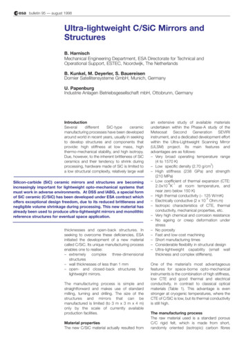
Measuringsurface roughnessand qualityPolished mould surfaces aretraditionally estimated by the nakedeye and/or measured by mechanicalprofilers for surface roughness,commonly described with the Ra, Rzand Rt values.However, these methods are bothsubjective and uncertain comparedto more advanced surface- andsub-surface measurement devicescapable of measuring to fractionsof nano-metres. The use of3D-instrumentation with higherresolution provides more accuratesurface measurements of mouldswith complex geometries which inturn means that quantitative surfacequality controls can be performed.SURFACE ROUGHNESS ACC.TO DIN/ISO 1302N1N2N3N4N5N6N7N8N9N 10N 11N 12ROUGHNESSRa, µm0.0250.050.10.20.40.81.63.26.312.52550SURFACE ROUGHNESS ACC. TO SPIROUGHNESSRmax, µm0.1-0.30.3-0.70.75-1.251.5-2.52-66-1010-2020-40 60 125 250 500ACHIEVED AFTER GRINDING/POLISHING WITHA-1A-2A-3B-1B-2B-3C-1C-2C-3D-1D-2D-33 μm Diamond Paste6 μm Diamond Paste15 μm Diamond Paste600 Grit Paper400 Grit Paper320 Grit Paper600 Grit Stone400 Grit Stone320 Grit Stone600 Stone Prior to Dry Blast Glass Beads #11400 Stone Prior to Dry Blast #240 Alminium oxide320 Stone Prior to Dry Blast #240 Aluminium oxideTable 6. Approximate comparison between requested surface roughness measured by mechanical profilers and internationalstandards.SURFACE ASSESSMENT BYROUGHNESS PARAMETERSThe benefit to measure surfaces isboth the possibility to study them inthe micro- and nano-scale, and a wayto quantitatively evaluate them. But,there is a huge amount of available2D- and 3D parameters (abbreviatedR- and S-parameters, respectively), sohow do you know which to use?2D parameters, usually obtained bya mechanical profiler, can be usedto quantify the surface quality in alimited extent. The most frequentused in practical work with mouldsis the Ra-value describing theaverage height of the measuredsurface. However, it is a rather poordescription of the mould surfacesince smaller defects and certaintextures will be “averaged out” and/or undetected. See figure 8.Ra – the arithmetical mean deviation of theprofile is the mean value of the absolutevalue of the profile departure y within thereference length l.Source: The figure to the left is fromT.R. Thomas book “Rough surfaces”2nd edition.0100200300400500600 µm050100150200250300350400450µmThe A- & B-profiles illustrate one ofthe major disadvantages of the 2Dprofilometry; A – a surface with pores,and B – a “defect free” surface, i.e. theresults are strongly dependent on theprofile location.Ra 2.4 µmIllustration of different surfacetopographies with equal Ra-value;i.e. the Ra-value itself is not enough toRa 2.5 µm fully describe the surface structureSource: Illustration from T.R. Thomasbook “Rough surfaces” 2nd edition.Ra 2.4 µmFig. 8.POLISHING OF MOULD STEEL 9
MEASUREMENT DEVICES AND ANALYSIS TECHNIQUES AVAILABLE TOQUANTIFY ENGINEERED SURFACE TOPOGRAPHIESLt1.75 mmLs2.5 µmVB350 µmVt0.50 mm/sPoints 3500Pick-up PHT 350Mechanical profiler (stylus)Typical outputparameters are theRa (arithmetic meanvalue of a profile),the Rz (mean peakto valley height),and the Rmax (or Rt, the maximumpeak to valley height). Notice: mostoften R-values are filtered per default(connected to actual measurementlength and cut-off).Sample D ground 15 rep Unimax 01µmP000 007 PCD: R(LC GS 0.3 mm)2.00-2.01.3 mm0.3 mm/divRa 0.083 µmRz 0.78 µmScatterometer (glossmeter)The surface isilluminated and thereflected/scatteredlight is detected.Simple glossmetersmeasure reflectionsin defined angles, whereasscatterometers include the totalreflection.Scattering data need to becorrelated to roughness databy verifications with othermeasurement devices. Typicaloutput is e.g. an average rmsvalues, the ratio of the diffusereflection or the reflection oflight at a defined angle.Intensity db500-5040-4020-2000-2020-4040Y scatter angle (degree)X scatter angle 201510509020406080100µm120140instruments are comingthat can be used for in-linemeasurements. Typical outputare 3D maps and areal surfaceparameters (e.g. Sa and Stwhich correspond to the Raand Rt respectively). Also otherparameter families are available,e.g. areal, volume and functionalparameters.0Height deviationsare detected byutilising interferencepatterns formed/arised when tworeflected lightbeams, one from the sample and onefrom a reference surface, interact.Features down to 1 µm in spatialresolution and sub-nm in height canbe detected. The technique is ofadvantages in laboratories due toits sensitivity to vibration, but new20040100µm6080120180160140nm180160Confocal microscope10 POLISHING OF MOULD STEEL01203040403020205060500 101019070809µm 0 100110 120 13807060quality. Typical output are3D maps and areal surfaceparameters (e.g. Sa and Stwhich correspond to the Raand Rt respectively). Also otherparameter families are available,e.g. areal, volume and functionalparameters.0 140 1590Builds up 3D mapsbased on stacks ofimages recordedat different heights,excluding pointsthat are out offocus. The technique is preferentialfor surfaces rougher than optical1400100806040200
SEM/EDSemitted electrons are “collected”by different detectors. The EDS, atype of X-ray spectrometer, allowselemental analysis. Typical output arethe topographical contrast (basedon SE), chemical contrast (based onBSE) and phase composition (basedon X-ray).A focused electronbeam raster-scansthe surface; theenergetic electronsinteract with theatoms in the samplewithin a few nm to several µm ofthe surface, i.e. scattering eventstake place (primary electrons looseenergy and/or change direction). TheAtomic force microscopeSimply described asa tiny profiler/stylusoperating withextremely smallprobe tips barelytouching the surfaceresulting in 3D resolutions close toatomic level. Typical output are 3Dmaps and areal surface parameters.µm3530252015105005101520253035 µmSelection of Measurement Devices and General SpecificationsGENERAO SPEC/ LIGHT LSEM/EDSATOMIC FORCEMICROSCOPEGLOSSMETERResolution (m)xy: 10-7z: 10-6xy: 10-6 – 10-4z: 10-9xy: 10-6z: 10-10xy: 10-4z: 10-7xy: 10-9z: 10-9xy: 10-10z: mµm-mmHeight ngLongShortmm-cmDevice dependentUnlimitedWork in vacuum,needs solidand conductingsamples, ability toimage undercutsNoise sensitive,fragile stylus/pick-upOnly averageroughness dataComponentanalysisUsabilityMeasurementtimeSize of workpiece Device dependentOtherStandardisedmethods forcleanlinessderminationUnlimitedRisk of surfacedamage, fragilestylus/pickupDevice dependent Device dependent(often up to(often up to2-10 kg)2-10 kg)Sensitive tovibrationsLarge depth offocus, problemswith artefactsTable 7. The figures shown should only be considered as guidelines.POLISHING OF MOULD STEEL 11
Choosing the right steel is of vital importance. ASSAB engineers andmetallurgists are always ready to assist you in your choice of theoptimum steel grade and the best treatment for each application.ASSAB not only supplies steel products with superior quality, we offerstate-of-the-art machining, heat treatment and surface treatmentservices to enhance steel properties to meet your requirement in theshortest lead time. Using a holistic approach as a one-stop solutionprovider, we are more than just another tool steel supplier.ASSAB and Uddeholm are present on every continent. This ensuresyou that high quality tool steel and local support are available whereveryou are. Together we secure our position as the world’s leadingsupplier of tooling materials.For more information, please visitwww.assab.com
Polishing The abrasives are more or less fixed in the carrier material and will cut and/or plough the surface. Buffing The abrasive adhere loosely to a flexible carrier (soft disk made of cloth or hide). This step is considered among some polisher to be the last polishing step performed in order to obtain a