Transcription
Project DocumentationDocument SPEC-0028Rev BM1 Mirror Polishing SpecificationChen LiangOptical Systems GroupApril 2014NameSignatureDatePrepared By:Chen LiangSenior Optical EngineerC. Liang21-Apr-14Approved By:Rob HubbardSystems EngineerR. Hubbard21-Apr-14Approved By:Tom BergerProject ScientistT. Berger15-Apr-14Approved By:Joseph McMullinProject ManagerJ. McMullin15-Apr-14Released By:Thomas RimmeleProject DirectorT. Rimmele15-Apr-14Advanced Technology Solar Telescope950 N. Cherry AvenuePhone 520-318-8102atst@nso.eduhttp://atst.nso.eduTucson, AZ 85719Fax 520-318-8500
M1 Mirror Polishing SpecificationREVISION SUMMARY:1.Date: 21 May 2010Rev: AChanges: Initial document for release.2,Date: 17 April 2014Rev: BChanges: Update information in Section 5 per CR-0478.SPEC-0028 Rev BPage ii
M1 Mirror Polishing SpecificationTable of Contents1.1.11.21.31.4M1 POLISHING OVERVIEW . 1SCOPE OF THE DOCUMENT . 1RELATED DOCUMENTS . 2GENERAL DEFINITIONS . 2VERIFICATION METHODS. 32.2.12.22.32.42.52.6ENVIRONMENTAL CONDITIONS . 4OPERATING ENVIRONMENT . 4SURVIVAL ENVIRONMENT . 4TRANSPORTATION ENVIRONMENT . 4CLEANING . 5COATING REMOVAL . 5COATING . 53.OPTICAL SURFACE SPECIFICATIONS . 64.SHIPPING CONTAINER SPECIFICATIONS . 95.INTERFACE SPECIFICATIONS . 10APPENDIX 1: M1 POLISHING FORCES . 12APPENDIX 2: DRAWINGS . 13SPEC-0028 Rev BPage iii
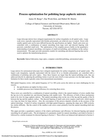
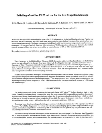
M1 Mirror Polishing Specification1. M1 POLISHING OVERVIEW1.1SCOPE OF THE DOCUMENTThis document consists of the requirements and specifications for design, fabrication (includingpolishing), testing and delivery of the M1 Mirror. The M1 Mirror is an off-axis paraboloid, acircular section of a larger Ø 12 meter on-axis paraboloid. The relationship of the M1 Mirrorwith respect to its parent optical axis and to the M2 Mirror (the secondary mirror) is shown inFigure 1 below.80001200M2 GREGORIAN SECONDARYM2 PARENT VERTEXOPTICAL AXISM1 PRIME FOCUSSPEC-0028 Rev BATST PRELIMINARY OPTICAL DESIGNM1 PARENT VERTEXM2 GREGORIANFOCUS2000(6000)4000M1 PRIMARY MIRROR24 JUNE 2002Figure 1. ATST M1-M2 optical design.Page 1
M1 Mirror Polishing Specification1.2RELATED DOCUMENTS 1.3ATST DWG-00001: M1 Blank - Detail–AMOS M1 Mirror Drawing: 2106 1010 001 FSPEC-0007: M1 Assembly SpecificationSPEC-0012 Glossary and Acronym ListSPEC-0020: M1 Coating ProcedureSPEC-0027: Coordinate System DefinitionSPEC-0029: ATST Optical PrescriptionSPEC-0034: Zerodur Blank SpecificationSPEC-0065: Quality Assurance RequirementsGENERAL DEFINITIONSActuator. The term “Actuator” refers to an electro-mechanical, hydraulic or pneumatic devicethat provides a controlled support force.Bidirectional Reflectance Distribution Function (BRDF). BRDF is a four-dimensionalfunction that defines how light is reflected at an opaque surface.Conic Constant (K). The Conic Constant is required to define the shape of the primary mirrorwith the radius of curvature. The Conic Constant k is related to the surface height (Z) as afunction of primary mirror radial position (r) from the parent vertex and Radius of Curvature (R).Figuring. Figuring is the process used to achieve the desired shape of an optical surface.Generating. Generating, or Generation, is the first step in figuring an optical surface and rapidlyremoves material using fixed-abrasive grinding.Optical Surface. The Optical Surface of the M1 is the polished surface shown in the referenceddrawings.Polishing. Polishing is the optical fabrication process that creates a finished surface on theprimary mirror.M1 Mirror. The M1 Mirror is the 4m diameter ATST primary mirror.M2 Mirror. The 0.65 meter diameter concave mirror in the ATST.Paraxial Radius of Curvature (R). The Paraxial Radius of Curvature is the center radius of theM1 parent surface, which along with the Conic Constant, is required to define the shape of theprimary mirror.Zenith Angle. The Zenith Angle is the angle between the primary mirror parent optical axis andthe vertical axis.SPEC-0028 Rev BPage 2
M1 Mirror Polishing Specification1.4VERIFICATION METHODSIncluded in each major numbered specification listed herein this document is a requirementverification method. These verification methods specify the minimum standards of verificationrequired by AURA to ensure that the individual requirements and specifications are met.All verification activities are the responsibility of the Contractor; i.e., the Contractor shall besolely responsible for providing any and all test equipment, analyses, inspections, and othermeans necessary to verify that the specifications and requirements have been met.Examples of verification methods include: Design Review. Verification by design review shall mean that the Contractordemonstrates to AURA during the appropriate design review that the equipment shallmeet the specification by way of its intrinsic layout and configuration.Analysis. Verification by analysis shall mean that Contractor analytically demonstratesthat the design meets the specification. Such analyses may include finite elementmethods, computation fluid analyses, closed form analyses, etc. All analyses shall beprovided to AURA in written report form, in both electronic (e.g., MS Word) and papercopy format.Inspection. Verification by inspection shall mean that the Contractor visuallydemonstrates to AURA personnel that the specification has been achieved on the as-builtequipment during factory acceptance testing.Test. Verification by test &/or measurement shall mean that Contractor empiricallydemonstrates that the as-built equipment meets the specification. Testing may be requiredin the factory during factory acceptance testing and/or at the Site during Site acceptancetesting.At a minimum, the specification compliance matrix provided by Contractor as part of the Workshall use the verification method(s) listed in each of the requirements sections below.All analyses, test results (with test error analysis) and other verification reports shall be providedto AURA in written report form, in both electronic (e.g., MS Word or Excel) and paper copyformat. For each test method used for acceptance testing, the Contractor shall perform a test erroranalysis. All potential errors effecting the measurement shall be listed and their influence on thetest results evaluated. The required measurement value shall be adjusted so the Test shall yield a99% or greater certainty that the specification has been met after taking the test error analysisinto account.SPEC-0028 Rev BPage 3
M1 Mirror Polishing Specification2. ENVIRONMENTAL CONDITIONS2.1OPERATING ENVIRONMENTThe M1 Mirror, while operating as a part of the ATST, shall be capable of sustained andcontinuous operation in complete conformance with the requirements of this specificationthroughout the expected life of the observatory while being continuously subjected to anycombination of the following environmental conditions:Altitude: sea level to 3100 metersAmbient temperature: 22 to -2 CAmbient temperature change rate: /-2 C/hrRelative Humidity: 0 to 70% (non-condensing)Wind speed: 0 to 5 m/sOrientation: Telescope pointing of 0 to 75 degrees Zenith Angle2.2SURVIVAL ENVIRONMENTThe M1 Mirror shall meet the requirements of Section 2.1 above, without damage or requirementfor repair, after being subjected to any combination of environmental conditions specified belowfor any duration of time during any number of occurrences throughout the expected life of theobservatory:Altitude: sea level to 3100 metersAmbient temperature: -10 to 27 CRelative Humidity: 0 to 95% (condensing)Wind speed: 0 to 15 m/sOrientation: Telescope pointing of 0 to 90 Zenith AngleSeismic Vibration: 3.0 g in any orientation2.3TRANSPORTATION ENVIRONMENTThe M1 Mirror shall meet the requirements of Section 2.1 above, without damage or requirementfor repair, after being subjected to any combination of environmental conditions specified belowfor any duration of time during any number of occurrences while packaged in a shippingcontainer:Altitude: sea level to 4500 metersAmbient temperature: -20 to 50 CRelative Humidity: 0 to 100% (condensing with salt spray)Wind speed: 0 to 70 m/sGravity Orientation: Optical Surface facing upSPEC-0028 Rev BPage 4
M1 Mirror Polishing SpecificationShock and Vibration: 10.0 g in any direction2.4CLEANINGThe Optical Surface of the M1 Mirror will be subject to periodic cleaning throughout the life ofthe observatory. The M1 Mirror shall meet the requirements of Section 2.1 above, withoutdamage or requirement for repair, after being subjected to cleaning with any combination of CO2snow, alcohol, acetone, detergents and water.2.5COATING REMOVALThe coating on the M1 Mirror will be subject to periodic removal and replacement throughoutthe expected life of the observatories using the procedures outlined in SPEC-0020. The M1 shallcontinue to comply with all the requirements of Section 2.1 above, without damage orrequirement for repair, after being subjected to any number of coating removals. Materials thatmay be used without limitation are; Hydrochloric acid, Cupric Sulfate, Potassium Hydroxide,Nitric Acid, Ceric Ammonium Nitrate, Calcium Carbonate, Potassium Ferrocyanide solutions,and Sodium Thiosulfate solutions.2.6COATINGThe Optical Surface of the M1 Mirror will be subject to regular coating throughout the life of theobservatory. The M1 shall continue to comply with the requirements of Section 2.1 above,without damage or requirement for repair, after being subjected to any number of such recoatings. Materials to be used for such coatings include, without limitation, aluminum, silver,silicon nitride, nickel chromium, silicon and hafnium oxide. Processes used during coating mayinclude, without limitation, evaporation or sputtering, which require vacuum environments in therange of 10-5 microns Hg pressures. The Optical Surface may be coated while facing either up ordown.SPEC-0028 Rev BPage 5
M1 Mirror Polishing Specification3. OPTICAL SURFACE SPECIFICATIONS1.2.1-0005 Optical Surface DescriptionThe theoretical M1 Mirror parent optical surface is a conic surface of revolution described by thefollowing equation:Z r2/(R(1 (1-(1 K)r2/R2)0.5)) with:R Radius of Curvature,K Conic Constant, andr distance from the parent optical axis.Verification: Acceptance TestRequirement Origin: Engineering1.2.1-0010 Paraxial Radius of CurvatureThe paraxial radius of curvature of the M1 mirror shall be:R 16 m 15.0 mm.Verification: Acceptance TestingRequirement Origin: Engineering1.2.1-0015 Conic ConstantThe Conic Constant of the primary mirror shall be:K -1.000.Verification: Acceptance TestRequirement Origin: Engineering1.2.1-0020 Surface Figure AccuracyThe Optical Surface of the M1 Mirror shall depart from the theoretical shape by less than 25 nmRMS after the following compensations have been applied: removal of tip tilt and piston errorsand active adjustment of M1 axial support forces described in Section 5 below.Verification: Acceptance Test, the vendor will verify that the Optical Surface complies with thesurface figure accuracy by performing full aperture interferometry. The spatial resolution of thephase map shall be a minimum of 500 by 500 pixels. The vendor will additionally verify thesurface figure accuracy via a second method. This second method shall be independent of theprimary interferometric test and is intended to exclude possible systemic errors in the primarytest method. This second method is preferably non-interferometric in nature.The Optical Surface specifications shall apply over a 4000 mm diameter projected onto theOptical Surface of M1Mirror, parallel to the optical axis of the parent parabola. It is importantSPEC-0028 Rev BPage 6
M1 Mirror Polishing Specificationto note that the optical surface is not perpendicular to the incoming solar beam, but tilted at anangle of approximately 14 ; this tilt causes the projected Ø 4000 mm clear aperture to becomean elliptical footprint when projected onto the M1 Mirror (see Figure 1).Requirement Origin: Engineering1.2.1-0021 Surface Figure Accuracy, Higher Spatial Frequency ErrorThe Optical Surface of the M1 Mirror shall depart from the theoretical shape by less than 8 nmRMS total, for higher spatial frequency error with spatial period from 1mm to 100mm, after thefollowing compensations have been applied: removal of tip tilt and piston errors and activeadjustment of M1 axial support forces described in Section 5 below.Verification: Acceptance Test, The vendor will verify that the Optical Surface complies with thesurface figure accuracy for higher spatial frequency error by performing Sub-apertureinterferometry. Sub-aperture interferometer measurements shall concentrate particularly atsupport locations and M1 edges.Requirement Origin: Engineering1.2.1-0025 Aspherical Surface SlideThe aspherical surface profile of the M1 mirror shall coincide with the optical axis of the M1parent mirror to within 2 mm.Verification: Acceptance TestRequirement Origin: Engineering1.2.1-0030 Encircled EnergyThe M1 mirror shall be such that the calculated Encircled Energy (EE) concentration, afterremoval of tip tilt and piston errors, and applying active adjustment of the M1 axial supportforces as described in Section 5 below, shall degrade, compared to an ideal telescope, by lessthan:Wavelength: 1600 nm50% EE Degradation Diameter 0.010 arcsecVerification: Acceptance Test (this test is expected to be performed at a single elevation angle ator near Zenith Pointing),Requirement Origin: Engineering1.2.1-0045 Surface ImperfectionsThe Contractor shall use its best efforts to minimize the number of surface imperfections in theOptical Surface. Within the Optical Surface, no surface imperfections of surface area larger than5.0 square millimeters shall be allowed, and a maximum of 200.0 square millimeters shall beallowed for the summation of all defective areas within the Optical Surface. No subsurfaceSPEC-0028 Rev BPage 7
M1 Mirror Polishing Specificationdamage shall be allowed to remain in any surface imperfection. Cracked material shall beremoved by a combination of grinding and etching.Verification: Acceptance TestRequirement Origin: Engineering1.2.1-0050 Surface Roughness.As a requirement, the Optical Surface shall be polished to less than 20 Angstroms RMS surfaceroughness.As a goal, the Optical Surface shall be polished to less than 10 Angstroms RMS surfaceroughness.Verification: Acceptance Test of minimally 20 arbitrary locations, chosen by AURA, distributedover the entire Optical Surface and covers a total area 0.01% of the Optical Surface.Requirement Origin: Engineering1.2.1-0055 Surface ScatterThe Optical Surface shall yield a Bidirectional Reflectance Distribution Function (BRDF) of lessthan 1.0 sr-1 at 0.002 radians from the specular direction.Verification: Acceptance Test of 20 arbitrary locations, chosen by AURA, distributed over theentire Optical Surface. This test shall be conducted with AURA representative present.Requirement Origin: Engineering1.2.1-0060 Local Decenter and Rotation of the Optical SurfaceThe position accuracy of the Optical Surface relative to the M1 Mirror support interface features(mounting hardware) shall be less than 2 mm in X-Y decenter and less than 2.0 arc minutes inrotation about the Z axis.Verification: Acceptance TestRequirement Origin: EngineeringSPEC-0028 Rev BPage 8
M1 Mirror Polishing Specification4. SHIPPING CONTAINER SPECIFICATIONSContractor shall be responsible for all aspects of shipping, including shipping arrangements,shipping, handling, and storage costs, transportation permits, customs and port of entry fees,taxes, and all other costs associated with transporting the M1 Mirror components from theContractor’s facility to the Site.All materials and equipment for shipment shall be prepared in such a manner as to protect themfrom damage in transit and storage. Special care shall be taken with electrical and electroniccomponents, which shall be packed with a dehumidifying agent to effectively deal withcondensation.Proper identification of parts and adequate provision for slinging and handling of equipmentwithout damage shall be made.All packaging, packing materials, slinging, and handling equipment design shall be approved byAURA.1.2.1-0065 General. The Vendor shall design, fabricate and deliver a reusable shipping containerthat is suitable for safely transporting M1 Mirror while being subjected to any combination of theTransportation Conditions listed in Section 2 above.Verification: Design Review & InspectionRequirement Origin: Engineering1.2.1-0070. Envelope. The size of the shipping container shall not exceed an envelope five (5)meters square on a side and two (2) meters in height.Verification: Design Review & InspectionRequirement Origin: Engineering1.2.1-0075. Lifter Compatibility. The design of the shipping container shall allow use of alifting fixture to remove and install the M1 Mirror that attaches to the M1 Mirror at six (6) placesequally spaced around the outer diameter of the M1 Mirror as shown in ATST DWG-00001 M1Blank, Detail.Verification: Design Review & InspectionRequirement Origin: EngineeringSPEC-0028 Rev BPage 9
M1 Mirror Polishing Specification5. INTERFACE SPECIFICATIONS1.2.1-0085 Configuration. The Vendor shall Generate, Figure and Polish the M1 Blank ensuringthat the finished Optical Surface be contained entirely within the “critical zone” of the M1 Blankas defined in ATST DWG-00001.Verification: Design Review & InspectionRequirement Origin: Engineering1.2.1-0090 Axial and Lateral Support Attachment. The lateral and axial support interface padswill be supplied by AURA prior to date specified in M1 Polishing SOW. The design of thelateral and axial support interface will be finalized as part of M1 Cell Assembly Contract. TheVendor shall select adhesive, bond joint design and install the M1 Mirror lateral and axialsupport interface pads as defined on drawing2106 1010 001 F. The bonded lateral and axialsupport interfaces shall be suitable for safe operation of the finished M1 Mirror while beingsubjected to any combination of the Operating and Survival Conditions listed in Section 2 abovewhile installed in the ATST as well as Coating and Cleaning processes.Verification: Design Review & InspectionRequirement Origin: Engineering1.2.1-0092 Metrology Support. The vendor shall support the M1 Mirror using the axial andlateral interface features while performing testing which demonstrates it conforms in all respectsto the requirements specified. The M1 shall be supported during testing on a mount that providessupport force vectors that can be reproduced by M1 Assembly support system as described byAMOS document “M1 Polishing Forces” given in Appendix 1. The direction of all supportforces shall be parallel to each other as indicated in 2106 1010 001 F, Detail.The axial support system used during the testing of the M1 shall have active force control toremove low order aberration terms in the polished surface. The axial support forces may beadjusted individually by up to 20 N relative to their nominal value to optimize the OpticalSurface figure for the purpose of Acceptance Testing.Verification: Design Review & InspectionRequirement Origin: Engineering.1.2.1-0095 M1 Mirror Stresses. The M1 Mirror shall not incur stresses exceeding 0.7 MPathrough any interface hardware. Special attention should be given to the interface hardwaredesign to minimize stresses imparted to the substrate.Verification: Design Review, AnalysisRequirement Origin: Engineering1.2.1-0100 Alignment Targets. The Vendor shall design and install alignment target registrationfeatures on the M1 Mirror to accurately locate the Optical Surface for the purpose of installationand alignment using a laser tracker measurement system. The location of the targets are definedSPEC-0028 Rev BPage 10
M1 Mirror Polishing Specificationon the drawing 2106 1010 001 F. The location of these targets relative to the measured opticalsurface geometry shall be delivered as part of acceptance test documentation. The accuracy inposition of these targets shall be within 100 microns of their reported position relative to themeasured Optical Surface geometry.Verification: Design Review & TestRequirement Origin: EngineeringSPEC-0028 Rev BPage 11
M1 Mirror Polishing SpecificationAPPENDIX 1: M1 POLISHING FORCESSee attached PDF “SPEC-0028 Apdx 1 - AMOS 2106 01 35 i2”.SPEC-0028 Rev BPage 12
ATST - M1 Mirror Cell :DISTRIBUTION LISTNameCompanyQuantityArchivesAMOS1 copyAude SOMJAAMOS1 copyMrs Kerry L. GONZALESNSO1 copyCHANGE RECORDISSUEDATENB OFPAGESMODIFICATIONS107/03/201413Initial issue226/03/201413Actuator numbering as in drawingsetREMARKSThis document is the property of AMOS. It can be neither disclosed nor duplicated without prior authorization.
ATST - M1 Mirror Cell 3TABLE OF CONTENTS1.SCOPE OF THE DOCUMENT .42.APPLICABLE DOCUMENTS .43.REFERENCE DOCUMENT.44.ACRONYMS.45.CONTEXT.56.AXIAL FORCES .66.16.27.PNEUMATIC FORCES .6HYDRAULIC FORCES .9RECOMMENDATIONS FOR POLISHING SUPPORT .13This document is the property of AMOS. It can be neither disclosed nor duplicated without prior authorization.
ATST - M1 Mirror Cell 41. SCOPE OF THE DOCUMENTThis document presents the axial support forces that are calculated for a best mirror figure innominal conditions (cell positioned horizontally) and that shall be used during mirrorpolishing.2. APPLICABLE DOCUMENTS[AD1]SPEC-0092 - M1 Cell Assembly Specification D3. REFERENCE DOCUMENT[RD1]2106 01 09 i3M1 Support Analysis Report[RD2]2106 01 34 i2AO – Analysis of asymmetric results[RD3]2106 30 31Axial Actuators Numbering4. SSFESITBCTBDWFEWFSwowrtAssembly Integration and VerificationAdvanced Mechanical and Optical Systems S.A.Active OpticsAdvanced Technology Solar TelescopeAssociation of Universities for Research in AstronomyCenter of GravityFinite ElementFinite Element ModelInterfaceNational Solar ObservatoryPeak to ValleyPiston, Tilt, FocusRequest For WaiverRoot Mean SquareSurface Figure ErrorInternational unit SystemTo Be ConfirmedTo Be Defined/DoneWave Front ErrorWave Front Sensorwithoutwith respect toThis document is the property of AMOS. It can be neither disclosed nor duplicated without prior authorization.23/05/2012
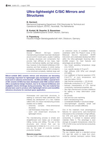
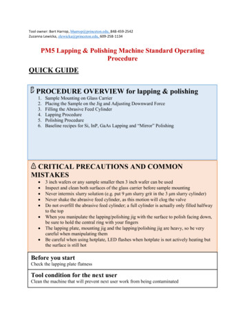
ATST - M1 Mirror Cell 26/03/201455. CONTEXTFollowing discussion with AURA about thethe mirrormirror polishingpolishing support,support, itit comescomes outout that:that:- Mirror will be polished on a 3-sectors3 sectors hydraulic support- Individual force adjustment will be done on each axial pad to replicate the axial-nominalaxial nominal forcedistribution.Here are the actuator numbering and hydraulic layout, as defined in the drawind set.HereHydr 2Hydr 1102001202 101 001302 201402 301502401501Hydr 3Figure 1: Actuator numbering – top viewwithout priorprior authorization.authorization.This documentdocument is the property of AMOSAMOS. It can be neither disclosed nor duplicated without
ATST - M1 Mirror Cell 66. AXIAL FORCESDue to the dual hydraulic-pneumatic support, axial forces applied to the mirror are a combination of:- A passive force given by the hydraulic support- A corrective force that can be adjusted individually on the pneumatic part of each actuatorBoth forces are applied in parallel configuration.6.1 PNEUMATIC FORCESThe pneumatic force distribution is constrained as follow:- The sum of pneumatic forces of actuators inside the same hydraulic sector is zero. Indeed, aconstant offset would be balanced by an opposite passive force of the corresponding hydraulicsector.- The sum of moments induced by pneumatic forces can not be constrained. It would avoid (orat least limit) deformation modes that are not 120deg-symmetrical. It is thus allowedpneumatic force set to generate moment on the hydraulic sector.Note that force sets have been slightly reviewed wrt results presented in [RD1]. Non-symmetricalbehaviour in force distribution has been corrected as described in 203204205206207208209210211212213214Pneumatic force 1.1-11.5-12.5-9.5-11.2This document is the property of AMOS. It can be neither disclosed nor duplicated without prior authorization.
ATST - M1 Mirror Cell This document is the property of AMOS. It can be neither disclosed nor duplicated without prior authorization.
ATST - M1 Mirror Cell 913.8Table 1: Pneumatic correction forcesThis document is the property of AMOS. It can be neither disclosed nor duplicated without prior authorization.
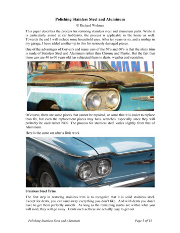
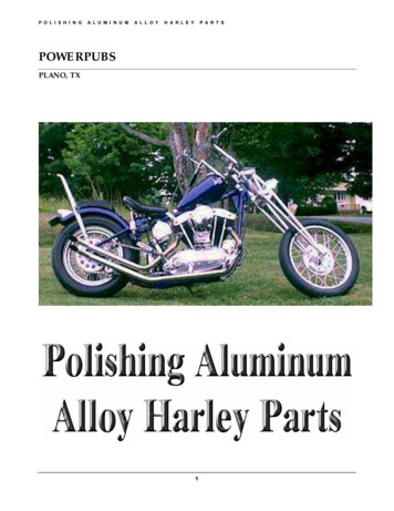
ATST - M1 Mirror Cell 9The force distribution on each ring is as follow:Hydr 1Hydr 3Hydr 2Note that the discontinuity of pneumatic force distribution in hydraulic sector #3 is due to the nonzero moment around X-axis due to the shape (astigmatism) that shall be corrected. This moment iscompensated by the hydraulic support, so when considering the total force (sum of pneumatic andhydraulic) applied to the mirror pad, the distribution is continuous.6.2 HYDRAULIC FORCESFEM analysis has identified the hydraulic support forces. They are 267.64 N in 2 sectors and 268.01N in the third oneTotal hydraulic support is 78 * 267.64 N 39 * 268.01 N 31328.31 NTotal mass is 3199.96 kg 31391.61 NThe missing 63 N are parasitic axial reactions at the 24 lateral supports.This document is the property of AMOS. It can be neither disclosed nor duplicated without prior authorization.
ATST - M1 Mirror Cell 10Note that these forces will be scaled with the real mass of the mirror.In addition, the hydraulic support will balance the pneumatic set of forces:- Force of the central actuator- Moment of pneumatic force inside on hydraulic sector.All of these forces are summarize in table 04205206207208209210211212213214NominalForce cingCentral 32-1.32-1.32-1.32-1.32BalancingMoment [N]0.001.571.571.571.571.571.57-3.14-3.14-3.
M1 Mirror Polishing Specification SPEC-0028 Rev B Page 1 1. M1 POLISHING OVERVIEW 1.1 SCOPE OF THE DOCUMENT This document consists of the requirements and specifications for design, fabrication (including polishing), testing and delivery of