Transcription
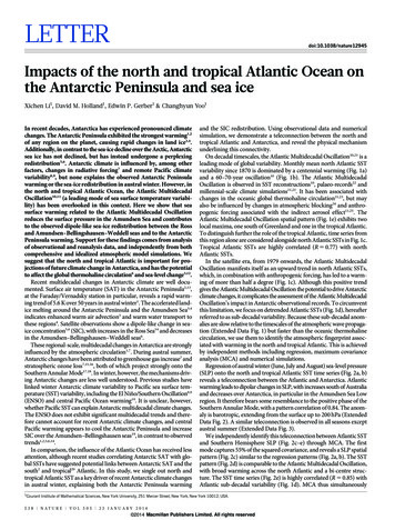
rbulletin 95 — august 1998Ultra-lightweight C/SiC Mirrors andStructuresB. HarnischMechanical Engineering Department, ESA Directorate for Technical andOperational Support, ESTEC, Noordwijk, The NetherlandsB. Kunkel, M. Deyerler, S. BauereisenDornier Satellitensysteme GmbH, Munich, GermanyU. PapenburgIndustrie Anlagen Betriebsgesellschaft mbH, Ottobrunn, manufacturing processes have been developedaround world in recent years, usually in seekingto develop structures and components thatprovide: high stiffness at low mass, highthermo-mechanical stability, and high isotropy.Due, however, to the inherent brittleness of SiCceramics and their tendency to shrink duringprocessing, hardware made of SiC is limited toa low structural complexity, relatively large wallSilicon-carbide (SiC) ceramic mirrors and structures are becomingincreasingly important for lightweight opto-mechanical systems thatmust work in adverse environments. At DSS and IABG, a special formof SiC ceramic (C/SiC) has been developed under ESA contract whichoffers exceptional design freedom, due to its reduced brittleness andnegligible volume shrinkage during processing. This new material hasalready been used to produce ultra-lightweight mirrors and monolithicreference structures for eventual space application.thicknesses and open-back structures. Inseeking to overcome these deficiencies, ESAinitiated the development of a new materialcalled C/SiC. Its unique manufacturing processenables one to realise:– extremely complex three-dimensionalstructures– wall thicknesses of less than 1 mm– open- and closed-back structures forlightweight mirrors.The manufacturing process is simple andstraightforward and makes use of standardmilling, turning and drilling. The size of thestructures and mirrors that can bemanufactured is limited (to 3 m x 3 m x 4 m)only by the scale of currently availableproduction facilities.Material propertiesThe new C/SiC material actually resulted froman extensive study of available materialsundertaken within the Phase-A study of theMeteosatSecondGenerationSEVIRIinstrument, and a dedicated development effortwithin the Ultra-Lightweight Scanning Mirror(ULSM) project. Its main features andadvantages are as follows:– Very broad operating temperature range(4 to 1570 K)3– Low specific density (2.70 g/cm )– High stiffness (238 GPa) and strength(210 MPa)– Low coefficient of thermal expansion (CTE:-6 -12.0x10 K at room temperature, andnear zero below 150 K)– High thermal conductivity ( 125 W/mK)-4– Electrically conductive (2 x 10 Ohm.m)– Isotropic characteristics of CTE, thermalconductivity, mechanical properties, etc.– Very high chemical and corrosion resistance– No ageing or creep deformation understress– No porosity– Fast and low-cost machining– Short manufacturing times– Considerable flexibility in structural design– Ultra-lightweight capability (small wallthickness and complex stiffeners).One of the material’s most advantageousfeatures for space-borne opto-mechanicalinstruments is the combination of high stiffness,low CTE and good thermal and electricalconductivity, in contrast to classical opticalmaterials (Table 1). This advantage is evenstronger at cryogenic temperatures, where theCTE of C/SiC is low, but its thermal conductivityis still high.The manufacturing processThe raw material used is a standard porousC/C rigid felt, which is made from short,randomly oriented (isotropic) carbon fibres
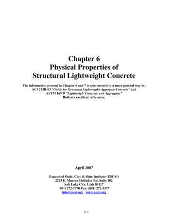
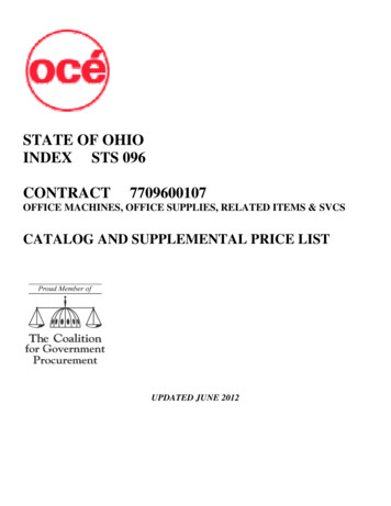
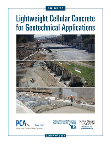
ultra-lightweight mirrors and structuresTable 1. C/SIC’s thermal properties compared with those of other materialsCTE @ RTThermal conductivitySpecific heatYoung’s ModulusSteady-state thermal distortionDynamical thermal distortionUnitsα 10-6 K-1kW/m KcJ/kg KEGPaE k/αE k/( c)(Fig.1). The latter are molded with phenolicresins at high pressures to form a type ofcarbon-fibre-reinforced plastic (CFRP) blank,which can be produced in various sizes. Duringa pyrolisation/carbonisation heat treatment atup to 1000ºC, the phenolic matrix reacts withthe carbon matrix (C/C-felt). The resulting socalled “green body” is then sufficiently rigid formilling to virtually any shape.MillingAs demonstrated in the ULSM mirrorprogramme, very complex structures can becut from a single green body by standardcomputer-controlled milling (Fig. 2). Ribs of1 mm or even less can be milled with astandard tolerance of 0.1 mm. This is one ofthe most significant advantages of this newmaterial, as it drastically reduces the formingcosts and enables the manufacture of trulyultra-lightweight mirrors, reflectors andstructures. It can also be machined to formstruts or tubes without the need to machinesupport structures in another material.InfiltrationThe milled green-body structure is thenmounted in a high-temperature furnace andheated under vacuum to temperatures at whichthe metallic silicon changes into the liquidphase (about 1400ºC). The liquid silicon reactswith the carbon matrix and the surface of thecarbon fibres to form a silicon-carbide matrix ina conversion process. The amounts of carbonand silicon have to be carefully apportioned 12481.52Be I-70A11194182028916932.8prevent a chemical reaction between the siliconand the reinforcing carbon fibres, and so IABGhas developed an optimised infiltration processwith precise computer control for differentsized chambers. The largest facility canprocess mirrors of up to 3 m diameter, or largestructures up to 3 m in diameter and 4 m long(Fig. 3).Grinding and polishingThe infiltrated mirror blank is ground to therequired surface figure. As the carbon-fibreFigure 1. REMmicrophotograph of thegreen-body chopped fibrematerialFigure 2. Milling operationson the 80 cm x 50 cmULSM blankFigure 3. The infiltrationfacility at IABG inOttobrunn (D)
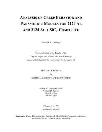
rbulletin 95 — august 1998 bullFigure 4. ULSM optical testmirror before and after ionbeam polishingFigure 5. Lightweightclosed-back structure with adiameter of 45 cm, madefrom six pieces joined in thegreen-body state andinfiltrated to a single unitcontent contributes to the micro-roughness ofthe surface, applications at near-infrared, visibleand X-ray wavelengths require a polishedcladding layer which acts as the opticalsurface.Several coating materials and depositiontechniques have been tested. The mostpromising candidates are monolayer chemicalvapour-deposition (CVD) SiC and directlybonded glass. Plasma-vapour-deposition(PVD) Si surfaces are also currently beingevaluated. In selecting the most suitablecladding material, the thermal expansioncoefficient matching, allowable thermallyinduced surface error and machinability have allto be taken into account. The differentialthermal expansion, the Young’s modulus of thesurface coating and the coating thickness haveto be optimised to keep bi-metallic bendingeffects in the mirror to a minimum.Although the CVD-SiC coating on the mirrorblank is a good candidate in terms of materialproperty matching, it is difficult to achieve ahigh optical quality due to the material’sexceptional hardness. Too high a pressure onthe polishing tool causes a “print through”effect, whilst insufficient pressure increasespolishing times and the optical performanceremains limited. It can, however, be improvedby introducing an additional ion-beam polishingstep.Ion-beam polishingAfter polishing the mirror by classical means,the optical surface is locally treated by plasmaetching to reduce the local errors in surfacefigure and achieve high optical performance.This process was developed by the Institut fürOberflächen-Modifikation in Leipzig for the 440mm-diameter optical test mirror for the ULSMprogramme. Figure 4 shows the interferogramsbefore and after the ion-beam treatment. Themirror’s rms surface figure error was improvedfrom 123 to 39 nm.Joining technologyThe C/SiC material has another big advantagewhich is not required in the normalmanufacturing process, but which is ofconsiderable benefit for larger mirrors andcomplex monolithic structures, namely thepossibility to join sub-components in the greenbody stage to form the final structure. Thisjoining technology allows one to manufacturemonolithic mirrors and structures larger thanthe available green-body C/C felts. It alsomakes it possible to assemble lightweightmirrors with closed back structures (Fig. 5), andcomplete instrument structures.The joining process starts with the gluing of thegreen-body parts using a special chemicaladhesive, developed at IABG, before Siinfiltration. During the subsequent Si-infiltration,the resin reacts to carbon so that a C/Cmaterial is generated which has the same
ultra-lightweight mirrors and structurespercentage of carbon fibres and carbon matrix,as well as the same porosity, as the rigidcarbon felt used. The infiltration process andthe reaction with the liquid silicon leads to amonolithic structure which has the samepercentage of the three material constituents(carbon fibres, SiC- and Si-matrix), and therebythe same mechanical and thermal properties asthe bulk C/SiC ceramic composite itself. This isideal for, for example, athermal telescopes withmirrors and structures with the same thermomechanical properties.C/SiC applicationsULSMThe C/SiC material was selected as candidatematerial for the Ultra-Lightweight ScanningMirror (ULSM) of the SEVIRI instrument on theMeteosatSecondGeneration(MSG)spacecraft. This mirror has to fulfil very stringentthermo-mechanical-stiffness and opticalquality requirements yet still have an ultra-lowmass. Operating in a geostationary orbit on aspacecraft rotating at 100 rpm, it is exposed toboth to the heat of the Sun and the intense coldof space and, due to its 45º inclination to thespin axis, to a maximum mechanical loading of3.2 g at the mirror tips, acting in oppositedirections.The mechanical design of the elliptical ULSMand one of the polished mirror blanks areshown in Figure 6. The mirror’s backingstructure contains square “pockets” 40 mmacross. The individual ribs are only 1.2 mmthick, with each containing a large cutout forstructural efficiency and to improve the mirror’sthermal properties, especially under vacuumconditions.The CVD-SiC surface coating has beensuccessfully applied and the optical surfacepolished to a specification of 60 nm rmssurface form error and less than 2 nm rmssurface micro-roughness. There was nomeasurable performance degradation afterassembly with the isostatic mounts and theCFRP frame (Fig. 7). The ULSM mirror hassince undergone mechanical and long-termthermal-cycling load tests, as well as extremetemperature tests, without showing anydeformation of the optical surface. Radiationhardness tests on the bulk material and thereflective coating were also performedsuccessfully using a small test mirror.Figure 7 . Interferogram of the assembled80 cm x 50 cm ULSMFigure 6. Design and hardware of the 80 cm x 50 cm Ultra Lightweight ScanningMirror (ULSM), which weighs just 7 kg
rbulletin 95 — august 1998 bulltriangular grid pattern with a rim thickness ofonly 1 mm and with internal cutouts is amongthe most complex ceramic structures of suchsize ever built. The mirror has been designed tohave a first eigenfrequency of over 400Hz anda structural safety margin of 3.9 at 60 g staticload.After fine machining and lapping to 8 micronrms accuracy, the mirror surface was coatedwith a 150 micron CVD-SiC layer. Samplepolishing tests have shown good homogeneityand that a surface micro-roughness of lessthan 1 nm rms can be achieved. The mirrorexhibited no change in radius of curvature afterthe CVD coating. The “as built” mass of themirror is just 6.2 kg.Figure 8. Rear of the 63 cmparabolic mirror for theATLID applicationFigure 9. Large verificationstructure for the SEVIRIthermal-stability test; themonolithic ceramic structureis 150 cm in diameter and200 cm highATLIDAnother example of highly efficient structuraldesign is the ATLID (Atmospheric LidarExperiment) parabolic mirror (F 0.9, aperture63 cm). In the stiffening structure (Fig. 8), allunnecessary material has been removed in atrade-off between stiffness and mass, includingin the area of the isostatic mounts. TheThree-dimensional structuresThe excellent “joinability” of the C/SiC materialallows individually machined parts andstructural elements to be combined to formcomplex 3D structure. The designer cantherefore manufacture a ceramic telescope orinstrument structures to final dimensions in thegreen-body state and then “infiltrate” them toform an integral ceramic component. C/SiCoptical components can be used incombination with C/SiC structures to buildathermal optical systems.In addition, monolithic ceramic truss structureswith better stiffness and thermo-mechanicalproperties than conventional all-aluminium orberyllium-type structures can be realised.Figure 9 shows such a large monolithic allC/SiC reference structure which is currentlybeing manufactured.ConclusionA process has been successfully developedthat allows C/SiC ceramic materials to be usedto manufacture highly complex, lightweight,high-stiffness mirrors and structures withexcellent dimensional stability. C/SiC reflectorscan be manufactured from a single piece ofgreen-body or, for larger reflectors up to 3 m indiameter, as separate segments which are thenjoined whilst in the green-body state. This novelapproach also allows one to realise closedback designs, which result in improvedstructural efficiency. Different polishable surfacecoatings have also been developed for specificapplications, which range from scanningmirrors to large telescope reflectors. Last butnot least, this all-ceramic instrumenttechnology delivers consistently high opticalperformance over a very wide temperaturerange.r
the polishing tool causes a “print through” effect, whilst insufficient pressure increases polishing times and the optical performance remains limited. It can, however, be improved by introducing an additional ion-beam polishing step. Ion-beam polishing After polishing the mirror by class