Transcription
DESIGN AND DEVELOPMENT OF MOULD CALCULATION SOFTWAREMUHAMAD IDZWAN BIN LATIFReport submitted in partial fulfillment ofthe requirements for the award ofBachelor of Manufacturing EngineeringFaculty of Manufacturing EngineeringUNIVERSITI MALAYSIA PAHANGJUNE 2013
vABSRACTManual calculation for injection moulding operation is time consuming andintends to make a miscalculation because of many parameters that need to beconsidered. In this project, mould calculation software is developed and design. It iscreated to help the users to calculate the injection moulding parameters that involvein some processes. The software is developed and design by using Microsoft VisualBasic 2008 programming. The formulae of injection moulding parameters are inputinto the software, in the form of computer coding. The interfaces of injectionmoulding parameters are created by using the graphics in Microsoft Visual Basic2008. At the end of the project, the Mould Calculations Software is created. The aidfrom software, time to calculate mould parameters in designing stage is shorter thanmanual calculation
viABSTRAKPengiraan secara manual untuk operasi acuan ini memakan masa danberkemungkinan untuk membuat perhitungan yang salahkerana banyak parameteryang perlu diambilkira. Dalam projek ini, perisian pengiraan acuan dibangunkan dandireka bentuk. Ia dicipta untuk membantu pengguna untuk mengira parameter acuanyang terlibat dalam beberapa proses. Perisian ini dibangunkan dan reka bentukdengan menggunakan Microsoft Visual Basic 2008pengaturcaraan. Formula acuanparameter input ke dalam perisian, dalam bentuk kod komputer. Muka parameteracuan dicipta dengan menggunakan grafik dalam Microsoft Visual Basic 2008. Padaakhir projek, PerisianPengiraan ParameterAcuan dicipta. Dengan bantuan daripadaperisian, masa untuk mengira parameter acuan dalam peringkat mereka bentukadalah lebih pendek daripada pengiraan manual
viiTABLE OF CONTENTSPageSUPERVISOR’S DECLARATIONiiSTUDENT’S DECLARATIONiiiACKNOWLEDGEMENTSivABSRACTvTABLE OF CONTENTSviLIST OF TABLESxiLIST OF FIGURESxiiCHAPTER 1:INTRODUCTION1.1Project background11.2Problem Statement11.3Project Objectives21.4Project Scopes21.5Project Significance / Impact2CHAPTER 2:LITERATURE REVIEW2.1Introduction of Mould32.2Mould Types32.2.1Two-Plate Mould42.2.2Three-Plate Mould52.3Basic mould contraction62.4Another part in mould construction72.4.1Sprue Bush72.4.2Register ring / Locating ring82.4.3Runner92.4.3.1 Cold runner102.4.3.2 Hot runner system10
viii2.4.4Gates system122.5Injection Moulding Process132.6Injection molding machine142.7Machine operation162.8Calculation172.8.1Shot Capacity172.8.2Plasticizing capacity182.8.3Cycle time202.8.4Clamping force202.8.5The number of cavities21a. Determination of cavity number by Shot capacity22b. Determination of cavity number by Plasticizing capacity 222.9c. Determination of cavity number by Clamping capacity222.8.6Gate size calculation232.8.7Runner size calculation24Software252.9.1Visual Basic252.9.2C Programming26CHAPTER 3:METHODOLOGY3.1Introduction283.2FLOW CHART OF METHODOLOGY293.3PROCESS FLOW CHART303.4Data e of the Software323.7.1Machine323.7.2Shot capacity343.7.3Plasticizing capacity353.7.4Cycle time363.7.5Clamping force38
ix3.7.6Number of cavity393.7.6.1 Shot capacity403.7.6.2 Plasticizing capacity413.7.6.3 Clamping force42Gate size423.7.7.1 Depth443.7.7.2 Width44Runner size453.8Implementation and Testing463.9Maintenance473.7.73.7.8CHAPTER 4:RESULT AND DISCUSION4.1INTRODUCTION484.2THE SOFTWARE484.2.1Front window-Plunger Type494.2.2Shot Capacity Calculation494.2.2.1About window – Shot Capacity52Calculation4.2.3The Plasticizing Capacity Calculation - The Plunger53and the Screw Type4.2.3.1About window – Plasticizing Capacity56Calculation4.2.4The Clamping Force Calculation - The Plunger and57the Screw Type4.2.4.1 About window – Clamping Force60Calculation4.2.5The Number of Cavity Calculation - The Plunger61and the Screw Type4.2.5.1Shot Capacity634.2.5.2About window – Number of Cavity65by Shot Capacity
x4.2.5.3Plasticizing Capacity674.2.5.4About window - The Number of69Cavity by Plasticizing Capacity4.2.5.5Clamping Force704.2.5.6About window - The Number of73Cavity by Clamping Force4.2.6The Gate Size Calculation - The Plunger and the75Screw Type4.2.74.2.6.1The Depth764.2.6.2About window - The Gate Size by Depth784.2.6.3The Width794.2.6.4About window - The Gate Size by Width82The Runner Size Calculation - The Plunger and the83Screw Type4.2.7.14.2.8About window - The Runner SizeThe Cycle Time Calculation - The Plunger and8687the Screw Type4.2.8.14.2.9About window - The Cycle TimeFront window - Screw Type4.2.10 Shot Capacity Calculation4.2.10.1About window - The Shot Capacity90929295CHAPTER 5: CONCLUSION AND FERENCES98APPENDIX99
xiLIST OF TABLESTable No.2.1PageRunner diameter based on type of resin24
xiiLIST OF FIGURESFigure No.Page2.1Two-plate mould42.2The Three plate moulds52.3The Basic mould construction62.4The location of sprue bush72.5Two basic design of sprue bush,8spherical recess and flat rear face2.6The Register ring / Locating ring92.7The hot runner system112.8Side gate122.9Submarine gate122.10Fan gate132.11Pin gate132.12The core and cavity plate142.13Injection molding machine152.14Injection molding machine172.15Event processor of visual basic253.1Process flow chart of simulation and experimental30mould calculation software3.2Main window333.3Type of machine window333.4Main window343.5Shot capacity calculation window353.6Main window353.7Plasticizing capacity calculation window363.8Main window373.9Cycle time calculation window373.10Main window383.11Clamping force calculation window39
xiii3.12Main window393.13Type of number of cavity window403.14Clamping force calculation window413.15Plasticizing capacity calculation window413.16Clamping capacity calculation window423.17Main window433.18Type of gate size calculation window433.19Gate size by depth calculation window443.20Gate size by width calculation window453.21Main window453.22Runner size calculation window464.1Type of the machine-Plunger Type494.2The coding of the plunger type window504.3Plunger Type window504.4The coding of shot capacity calculation514.5The shot capacity window524.6The coding of About window524.7The About window534.8The coding of plasticizing capacity window544.9The process operation plasticizing capacity window544.10The coding of plasticizing capacity calculation554.11The plasticizing capacity window564.12The coding About window564.13The About window574.14The coding of clamping force window584.15The clamping force window584.16The coding of clamping force calculation594.17The clamping force calculation604.18The coding of About window604.19The About window614.20The coding of the clamping force calculation624.21The number of cavity window63
xiv4.22The code of the number of cavity window634.23The number of cavity – shot capacity window644.24The coding of number of cavity - shot capacity644.25The number of cavity - shot capacity window654.26The coding of About window664.27The About window664.28The code of the number of cavity window674.29The number of cavity -plasticizing capacity window674.30The coding of number of cavity - plasticizing capacity684.31The number of cavity - plasticizing capacity window694.32The coding of About window694.33The About window704.34The code of the number of cavity calculation714.35The number of cavity – Clamping force window724.36The coding of number of cavity - clamping force724.37The number of cavity - clamping force window734.38The coding of the number of cavity - shot capacity744.39The About window744.40The coding of the gate size754.41The gate size window764.42The coding of the gate size - the depth calculation764.43The gate size – depth window774.44The coding of the gate size -the depth774.45The gate size – depth window784.46The coding gate size – depth794.47The About window794.48The coding of the gate size - the width804.49The gate size – width window814.50The coding of gate size – width814.51The gate size – width window824.52The coding gate size – depth834.53The About window83
1CHAPTER 1INTRODUCTION1.1Project BackgroundThe project is about developing the plastic injection mould calculationsoftware. Its involves parameters such as shot capacity, clamping pressure, plasticsize capacity, calculation cycle time, number of cavities that determine by shotcapacity, by plastic size capacity and by clamping capacity, gate and runner size .These criteria are important in injection moulding process.Sofware that used todevelope the mould calculation sofware are visual basic and C programming. Theresult from the moulding calculation sofware will make the injection database moreaccurate. These two combination of sofware will make the mould calculation becamemore effective and save the time for doing calculation by the manually. At the end ofthe project, the sofware will be give a lot of benefit to the manufacturer especially ininjection moulding process.1.2Problem StatementManufacturers may have some difficulties in finding commercial software forplastic injection mould parameter estimation which really suits their immediate use.Some existing software in the market has many restrictions in data entry. Even
2though the software is easy to use, users require a long time to become famaliar withthe software. They are time consuming for learning, not user friendly if users do notwell understand the meanings for individual input.1.3ObjectivesThe objectives that going to achieve in this system is:i.To design mould parameter calculation sofware system.ii.To develop mould parameter sofware system with the injection database.1.4ScopeThe scope of the project is:Developing the mould calculation software by using visual basic2Creating a database of the injection parameters.1.51Project Significance / ImpactThere are few benefits that a user can gain from this software system such asit will savethe calculation time. Futhermore, the calculation will be more accurate.Besides that, this system also assist industrial practitioner in producing an accuratecalculation for certain mould manufacturing projects. The usage of mobile devicesresults in improved data accuracy and increased mobility and convenience therebystreamlining movement and reducing human errors. Mobile devices increaseproductivity through reduced data entry efforts, reduced data capture activities,streamlined user time-motion efforts, enables process automation which increasesthroughput and decreases cycle-times.
3CHAPTER 2LITERATURE REVIEW2.1MouldMould is the common terms used to describe the tooling used to produceplastic parts in moulding. It’s usually only used in mass production where thousandsof parts were being produced. Typical moulds are constructed from hardened steel,pre-hardened steel, aluminum, and/or beryllium-copper alloy. The choice of materialto build a mould from is primarily one of economics; in general, steel moulds costmore to construct, but their longer lifespan will offset the higher initial cost over ahigher number of parts made before wearing out. Pre-hardened steel moulds are lesswear-resistant and are used for lower volume requirements or larger components[1].2.2Mould TypesMould is the production tooling used to produce plastic parts inmoulding.There are two type of mould. There are two-plate mould and three-platemould.Both of the mould type have different characteristic.
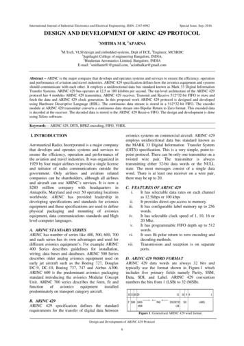
42.2.1Two-Plate MouldThe two plate mould is simple in design, yet versatile. It consists of a frontand stationary half. The cavity or core can be mounted on either half, dependingupon the part design and the location of the location of the knock-out pins. Thismould is easily adapted for different designs and all part ejection methods.Thestandard mould (Figure 2.1) is the most simple design, basically the standard mouldsis same as two plate moulds construction, they divided in two side : cavity side andcore side, cavity side is the side that construct to flowing plastic material from nozzleto cavity parts, basically they consist of sprue, runner.Figure 2.1: Two-plate mouldCore side constructed to make shape for core, demolding system and ejectionsystem, at this side the design ejection system.Standard mould have one parting line,and have one opening direction. this type of mould use in all kinds of plastic partsthat doesn't have undercut, inner and outer screw.Light brown color little and straightin ejection system is shown ejector pin.
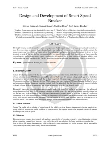
52.2.2Three-Plate MouldThis type of mould (Figure 2.2) is used primarily to centre gate or submarinegate parts in multiple cavities. It consists of the standard two-plate design with thethird movable between the two. Automatic degating is possible with three-platemoulds, but runner scrap is increased.Basically three plate moulds has two partingline, and floating plate, floating plate support by support pin, Since the mould hastwo parting planes, the runner system can be located on one side of floating plate ormake special plate that attach in floating plate, we called runner plate, see postabout runner plate. Three plate moulds are used because of their flexibility in gatinglocation. this types of moulds is flexible even use in multiple cavity.Figure 2.2:The Three plate moulds
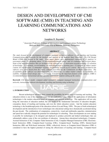
62.3Basic mould constructionTheFigure 2.3 below show Three-Plate Mouldbase type with closed position,basically 3 plate type and 2 plate type has some main plate.Figure 2.3:The Basic mould contruction1. Fixed Clamping Plate or Top Plate: The function of top plate is to holds thefixed side of the mould to attached at the fixed platen of the injectionmachine at this plate will attach locating ring, eye bolt, and sprue bush.2. Runner Stripper Plate: The runner stripper plateonly used in 3 plate mouldstype, the function is to cut resin from nozzle in top of sprue bush, and pull therunn
To design mould parameter calculation sofware system. ii. To develop mould parameter sofware system with the injection database. 1.4 Scope The scope of the project is: 1 Developing the mould calculation software by using visual basic 2 Creating a database of the injection parameters. 1.5 Project Significance / Impact There are few benefits that a user can gain from this software system such as .