Transcription
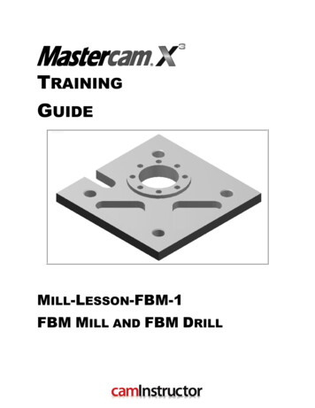
TRAININGGUIDEMILL-LESSON-FBM-1FBM MILL AND FBM DRILL
Mastercam Training GuideObjectivesPreviously in Mill-Lesson-6 and Mill-Lesson-7 geometry was created and machined usingstandard Mastercam methods. This lesson will apply Feature Based Machining (FBM) methodsincluding FBM Mill and FBM Drill to a solid model previously created in SolidWorks.Feature Based Machining (FBM)FBM eliminates manual feature identification for programming milling and drilling operations onsolid parts. The FBM Mill and FBM Drill operations automatically create the toolpaths needed tomachine features that are identified using your specific criteria. FBM's interface is simple andintuitive.You will generate the toolpaths for MILL-LESSON-FBM-1 to machine the part on a CNC verticalmilling machine.This Lesson covers the following topics:Establish Stock Setup settings:Stock size.Material for the part.Feed calculation.Generate a 2-dimensional milling toolpathconsisting of:FBM Mill operation and child toolpath operations.FBM Drill operation and child toolpath operations.Inspect the toolpath using Mastercam’s Verify by:Launching the Verify function to machine the part on the screen.Generating the NC- code.Mill-Lesson-FBM-1 - 1
Mill-Lesson-FBMMILL-LESSON-FBM-1 DRAWINGMill-Lesson-FBM-1 - 2
Mastercam Training GuideTOOL LIST3.0 face mill to face the part to thickness.1.0 flat end mill to rough machine around 2.0” diameter boss.0.5 diameter flat end mill to rough machine the pockets and 1.25 bore.0.375 diameter flat end mill to rough machine the slot and finish all areas.0.375 diameter spot drill all holes.0.1875 diameter drill to drill the bolt hole circle.0.3125 diameter drill to tap drill the 3/8-16 UNC tapped holes.3/8-16 UNC tap to tap holes.0.5 countersink to countersink the 3/8-16 UNC tapped holes.Mill-Lesson-FBM-1 - 3
Mill-Lesson-FBMMill-Lesson-FBM-1 - 4
Mastercam Training GuideMILL-LESSON-FBM-1 - THE PROCESSToolpath CreationTASK 1: Import part geometry from SolidWorksTASK 2: Setting the environmentTASK 3: Translate part geometry to machining originTASK 4: Define the rough stock using stock setupTASK 5: Run FBM Mill for all milling operationsTASK 6: Verify the toolpathTASK 7: Run FBM Drill for all hole making operationsTASK 8: Verify the toolpathTASK 9: Remove the Outside Finish PassTASK 10: Save the updated MCX fileTASK 11: Post and create the CNC code fileMill-Lesson-FBM-1 - 5
Mill-Lesson-FBMTASK 1:IMPORT PART GEOMETRY FROM SOLIDWORKSIn this lesson you will use an imported solid model.1. Click on File Open2. Beside Files of Type click on the drop down arrow and select SolidWorks Files(*.SLDPRT;*.SLDASM)3. On the multimedia CD that came with this text is a folder called Mastercam-Files browseto this location and select Mill-Lesson-FBM-1.SLDPRT4. Select the green check mark buttonto load the file and complete this function.Mill-Lesson-FBM-1 - 6
Mastercam Training Guide5. The screen should look like the one below:6. Select File Save as 7. In the File name box, type Mill-Lesson-FBM-1.8. Save to an appropriate location.9. Select the green check mark buttonto save the file and complete this function.TASK 2:SETTING THE ENVIRONMENTBefore starting the geometry import you should set up the grid, toolbars and machine typeas outlined in the Setting the environment section at the beginning of this text:1. Set up the Grid. This will help identify the location of the origin.2. Customize the toolbars to machine a 2D part.3. Set the machine type to a Haas Vertical Spindle CNC machine.Mill-Lesson-FBM-1 - 7
Mill-Lesson-FBMTASK 3:TRANSLATE PART GEOMETRY TO MACHINING ORIGINTranslating the geometry between 2 points.1. Select the Xform Translate. icon.from the General Selection Ribbon Bar.2. Select the All. buttonfrom the Select All dialog Box.3. Select the All Entities button.4. Pick the End Selection icon5. Select the Move radio button and enter Delta vales of X 1.75, Y 2.75, and Z 0.6. Select the OK buttonto complete the geometry translation.7. Click on the Clear Colors.8. Select the Fit to screen icon.9. The screen should look like the one below:Mill-Lesson-FBM-1 - 8
Mastercam Training GuideToolpath CreationTASK 4:DEFINE THE ROUGH STOCK USING STOCK SETUPDefining the Rough Stock using stock setup.1. Select the Fit to screen icon2. Select the plus in front of Properties to expand the Toolpaths Group Properties. Alt-O willShow/hide Operations Manager pane.3. Select Stock setup in the toolpath manager window as shown above on the right:4. Change the parameters to match the Stock Setup screenshot below:The bottom face of the material has been pre-machined and is not part of the toolpathoperations for this lesson.The material has also been pre-machined to 4.5 x 4.5 and is not part of the toolpathoperations for this lesson.Z zero is at the bottom of the part.Mill-Lesson-FBM-1 - 9
Mill-Lesson-FBM5. Select the Tool Settings tab and change the parameters to match the Tool Settingsscreenshot below. To change the Material type follow the next set of instructions.6. To change the Material type to Aluminium 6061 pick the Select button at the bottom of theTool Settings page.7. At the Material List dialog box open the Source drop down list and select Mill – library.Mill-Lesson-FBM-1 - 10
Mastercam Training Guide8. From the Default Materials list select ALUMINIUM inch - 6061 and then select9. Select the OK button.again to complete this Stock Setup function.TASK 5:RUN FBM MILL FOR ALL MILLING OPERATIONSIn this task you configure settings in FBM Mill to set up tools and interrogate the solid tocreate machining regions and apply toolpath strategies.1. From the menu bar select Toolpaths FBM Mill FBM Mill is a new method for quicklyproducing the equivalent of standard Face,Pocket, and Contour toolpaths. A singleParent operation is used to interrogate thesolid model, detecting the part’s features anddetermining machining zones. A single set ofconfiguration settings will address facing,roughing, rest milling, floor and wall finishing,and outside contouring. Child operations arecreated using 2D High Speed, Face, Pocket,and Contour operations. The parameters ofChild operations can be edited for furthercustomization.Mill-Lesson-FBM-1 - 11
Mill-Lesson-FBM2. On the screen you will now see the FBM Toolpaths – Mill dialog box, starting with theSetup page selected in the Tree Control menu down the left hand side:3. From this page you will select Preferred tooling which will be set up in a future step. Youwill also elect to rough and finish the outside of this part, to ensure the 1/2” slot is address.Your selections should appear as follows:4. Click on Feature detection in the Tree Control menu on the left of the dialog box.Mill-Lesson-FBM-1 - 12
Mastercam Training Guide5. You will leave the default settings, which should be as follows:6. Click on Facing tools in the Tree Control menu. You will select a Facing tool from the ToolLibrary.7. Right click in the empty white space in the Preferred tools list and left click on Select toolfrom library.8. Use the slider bar on the right of this dialog box to scroll down and locate a 3.0 diameterface mill. Select the 3.0 diameter face mill by picking anywhere along the row.9. Select the OK buttonto complete the selection of this tool.Mill-Lesson-FBM-1 - 13
Mill-Lesson-FBM10. Right click on the Face mill you’ve just added, and select Edit tool.11. Left click on the Parameters tab and change the Feed rate, Plunge rate, and Retract rateto 20.0, and the Spindle speed to 1500.to complete these changes in Parameters.12. Select the OK button13. Click on Roughing tools in the Tree Control menu. You will select Roughing tools from theTool Library.14. Right click in the empty white space in the Preferred tools list and left click on Select toolfrom library.Mill-Lesson-FBM-1 - 14
Mastercam Training Guide15. Use the slider bar on the right of this dialog box to scroll down and locate a 1.0 diameterflat end mill. Select the 1.0 diameter flat end mill by picking anywhere along the 1.0 endmill row, as shown below:to complete the selection of this tool.16. Select the OK button17. Right click on the Endmill you’ve just added, and select Edit tool.18. Left click on the Parameters tab and change the Feed rate, Plunge rate, and Retract rateto 10.0, and the Spindle speed to 1300.19. Select the OK buttonto complete these changes in Parameters.Mill-Lesson-FBM-1 - 15
Mill-Lesson-FBM20. Right click in the empty white space in the Preferred tools list and left click on Select toolfrom library.21. Use the slider bar on the right of this dialog box to scroll down and locate a 0.5 diameterflat end mill. Select the 0.5 diameter flat end mill by picking anywhere along the 0.5 endmill row, as shown below:22. Select the OK buttonto complete the selection of this tool.23. Set the feeds and speeds for this tool to 10”/min and 3000 RPM by repeating the steps usedon the previous tool.24. Click on Restmill tools in the Tree Control menu. You will select a Restmill tool from theTool Library.25. Right click in the empty white space in the Preferred tools list and left click on Select toolfrom library.Mill-Lesson-FBM-1 - 16
Mastercam Training Guide26. Use the slider bar on the right of this dialog box to scroll down and locate a 0.375 diameterflat end mill. Select the 0.375 diameter flat end mill by picking anywhere along the row.to complete the selection of this tool.27. Select the OK button28. Set the feeds and speeds for this tool to 8”/min and 4750 RPM by repeating the steps usedon the previous tool.29. Click on Finish tools in the Tree Control menu. You will select a Finish tool from the list oftools you have just added.30. Right click in the empty white space in the Preferred tools list and left click on Select toolfrom MCX.31. Select the 3/8 FLAT ENDMILL you just added as a Restmill tool.32. Select the OK buttonto complete the selection of this tool.Mill-Lesson-FBM-1 - 17
Mill-Lesson-FBM33. Next you will set Facing cut parameters, selecting Facing from the Tree Control dialog box,and adjusting settings for 1 rough cut, and selecting Zigzag.Your selections should be set as follows:34. Next you will set Roughing cut parameters, selecting Roughing from the Tree Control dialogbox, and adjusting settings for Profile ramp entry, 75% of diameter XY Stepover, 25% ofdiameter Depth Cuts, and 0.015” Stock to leave on walls. Your selections should be setas follows:Mill-Lesson-FBM-1 - 18
Mastercam Training Guide35. Next you will set Restmill cut parameters, selecting Restmill from the Tree Control dialogbox, and adjusting settings for 75% of diameter XY Stepover, 25% of diameter Depth Cuts,and 0.015” Stock to leave on walls. Your selections should be set as follows:36. Select Floor Finish from the Tree Control dialog box and uncheck Enable floor finishin order to disable floor finishing.37. Next you will set Finish cut parameters, selecting Wall Finish from the Tree Control dialogbox, and adjusting settings for 1 Finish Pass, 1 Depth Cut, and Perpendicular Entry / Exitmoves with lines and arcs that are 10% of the tool’s diameter. Your selections should beset as follows:Mill-Lesson-FBM-1 - 19
Mill-Lesson-FBM38. Select Linking Parameters from the Tree Control dialog box. You will use a Clearancevalue of 2” above the Stock model, with 0.1” Retract and Feed plane values:39. Select Coolant from the Tree Control dialog box. Set Flood to On:to process all milling operations for this part.40. Select the OK button41. When prompted to Enter new NC name ensure MILL-LESSON-FBM-1 is displayed andthen select the OK button.TASK 6:VERIFY THE TOOLPATHMastercam's Verify utility allows you to use solid models to simulate the machining of a part.The model created by the verification represents the surface finish, and shows collisions, ifany exist.This allows you to identify and correct program errors before they reach the shop floor.1. For a better view of the part use the toolbar at the top of the screen to change the graphicsview to Isometric.2. In the Toolpath Manager pick all the operations to verify by picking the Select All icon3. Select the Verify selected operations button circled below:4. Adjust the Verify speed to midway along the speed control bar.Mill-Lesson-FBM-1 - 20.
Mastercam Training Guide5. Select the play button to verify the toolpaths.The verified toolpaths are shown below.6. Select the OK buttonto exit Verify.Mill-Lesson-FBM-1 - 21
Mill-Lesson-FBMTASK 7:RUN FBM DRILL FOR ALL HOLE MAKING OPERATIONSIn this task you configure settings in FBM Drill to interrogate the solid, identify hole features,and apply holemaking strategies.1. From the menu bar select Toolpaths FBM Drill FBM Drill is a new method for quicklyproducing the equivalent of standard Drilltoolpaths. A single Parent operation is used tointerrogate the solid model, detecting thepart’s hole features and apply the necessarilyholemaking operations. A single set ofconfiguration settings will address spot drilling,drilling, tapping, and boring. Child operationsare created using standard Drill operations.The parameters of Child operations can beedited for further customization.2. On the screen you will now see the FBM Toolpaths – Drill dialog box, starting with theSetup page selected in the Tree Control menu down the left hand side:3. From this page you will change the Sorting option by clicking on the current Sortingmethod iconMill-Lesson-FBM-1 - 22
Mastercam Training Guide4. Select the Point to Point 2D Sort Method5. Select the OK buttonin the 2D sort page.6. The prompt now changes to Select sorting start point. Move the mouse and position thecursor over the point at the center of circle shown below, you will notice this iconappears as you move over the point at the center of this circle. This cross denotes you aresnapping to a circle center point. Use the left button of your mouse to pick this point.Mill-Lesson-FBM-1 - 23
Mill-Lesson-FBM7. Select Hole Detection from the Tree Control dialog box and set parameters to Includeblind hole and to Limit search to plane TOP as follows:8. Select Deep Drilling from the Tree Control dialog box and uncheck Deep drilling.9. Select Spot Drilling from the Tree Control dialog box and check Spot drilling.Mill-Lesson-FBM-1 - 24
Mastercam Training Guide10. Select Pre-drilling from the Tree Control dialog box and check Pre-drilling.The 3/8-16 UNC tapped holes will require Pre-drilling with a 5/16” drill. You will use anAdditional break through of .1” for this part which features all through holes.11. Select Tools from the Tree Control dialog box. You will allow FBM Drill to automatically Usetool library by apply the follow settings:Mill-Lesson-FBM-1 - 25
Mill-Lesson-FBM12. Select Linking Parameters from the Tree Control dialog box. This dialog box will be usedto set our Clearance at Solid height plus 1.”, Retract at Solid height plus 0.1”, anAdditional break through of .1”, and No adjustment for the Tap / Ream adjustment forthis part which features all through holes.13. Select Coolant from the Tree Control dialog box. Set Flood to On:14. Click the Detect. button at the top of the FBM Toolpaths – Drill dialog box.Mill-Lesson-FBM-1 - 26
Mastercam Training Guide15. Your screen should appear as follows:16. Left click on the first 0.375 Dia. Hole in the list.17. Press and hold the Ctrl key on your keyboard. Left click on the next three 0.375 Dia. Holesin the list. With Ctrl still held, you can select and unselect any mistakes. When the fourcorrect holes are selected, release the Ctrl key.Mill-Lesson-FBM-1 - 27
Mill-Lesson-FBM18. Right click on any of these four selected rows, in the Hole type column who’s valuecurrently reads Drill. Hover the cursor over Hole type and select TAP RH from the list.19. Select the OK buttonto process all holemaking operations for this part.Drill cycles used are selected based on the cycle set within each tool stored in the tool library.With the selection of Feed Calculation From Tool in the Machine Group Properties ToolSettings tab, all feeds and speeds are set based on the values set in the Tool Libraries.Many users take the time to create a custom tool library with only their tools, with desiredfeeds and speeds set in the library.TASK 8:VERIFY THE TOOLPATHMastercam's Verify utility allows you to use solid models to simulate the machining of a part.The model created by the verification represents the surface finish, and shows collisions, ifany exist.This allows you to identify and correct program errors before they reach the shop floor.1. For a better view of the part use the toolbar at the top of the screen to change the graphicsview to Isometric.2. In the Toolpath Manager pick all the operations to verify by picking the Select All icon3. Select the Verify selected operations button circled below:4. Adjust the Verify speed to midway along the speed control bar.Mill-Lesson-FBM-1 - 28.
Mastercam Training Guide5. Select the play button to verify the toolpaths.The verified toolpaths are shown below.6. Select the OK buttonto exit Verify.TASK 9:REMOVE THE OUTSIDE FINISH PASSThe drawing for this lesson noted that the stock size is equal to the outside dimensions of thepart. We configured FBM Mill to Rough outside of part and to Finish outside of part inorder to address the slot. However, the complete outside finish pass around the part isundesirable for work holding. FBM child operations can be edited independently of theparent parameters. In this task you will edit the outside profile Chain to address only the slot,and modify the Lead in/out parameters.1. Use the Operations Manager on the left side of the Mastercam interface Locate Operation15 – Contour (2D) within the Outside Profile-TOP Toolpath Group. Click on the Geometryicon.Mill-Lesson-FBM-1 - 29
Mill-Lesson-FBM2. Right click on Chain 1 and select Rechain all3. Right click in the Geometry window and select the Isometric GView. Right click again andselect Fit.4. Press and hold the Alt key on your keyboards and type s to toggle shading in Mastercam.This Key mapping shortcut is often denoted as Alt S . Toggle shading until it is Off andthe full wireframe is visible.5. Select Partial chaining. When prompted for Select the first entity, pick line 1. Next promptSelect the last entity pick line 2. Final prompt Branch point reached. Select nextbranch pick the slot radius 3.6. Select the OK buttonto complete the Chain selection.to complete the Chain Manager.7. Select the OK button8. Still focusing on Operation 15 – Contour (2D) in the Operations Manager click on theParameters icon.Mill-Lesson-FBM-1 - 30
Mastercam Training Guide9. In the Contour Parameters Tab select the Lead in/out button10. Set the parameters for Tangent lines and arcs, sized at 100% of the tool’s diameter.11. Select the OK buttonto close the Lead in/out dialog box.to close the Contour 2D dialog box.12. Select the OK button13. Regenerate all dirty operations to refresh this modified Operation.TASK 10:SAVE THE UPDATED MCX FILE1. Select File.2. Select Save.Mill-Lesson-FBM-1 - 31
Mill-Lesson-FBMTASK 11:POST AND CREATE THE CNC CODE FILE1. Ensure all the operations are selected by picking the Select All iconmanager.from the Toolpath2. Select the Post selected operations button from the Toolpath manager.3. Please Note: If you cannot see G1 click on the right pane of the Toolpath manger windowand expand the window to the right.4. In the Post processing window, make the necessary changes as shown below:5. Select the OK buttonto continue.6. Ensure the same name as your Mastercam part file name is displayed in the NC File namefield as shown below:7. Select the Save button.Mill-Lesson-FBM-1 - 32
Mastercam Training Guide8. The CNC code file opens up in the default editor:9. Select thein the top right corner to exit the CNC editor.This completes Mill-Lesson-FBM-1.Mill-Lesson-FBM-1 - 33
Mastercam Training Guide Mill-Lesson-FBM-1 - 3 TOOL LIST 3.0 face mill to face the part to thickness. 1.0 flat end mill to rough machine around 2.0" diameter boss. 0.5 diameter flat end mill to rough machine the pockets and 1.25 bore. 0.375 diameter flat end mill to rough machine the slot and finish all areas. 0.375 diameter spot drill all holes.