Transcription
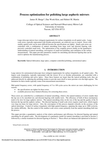
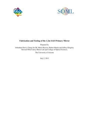
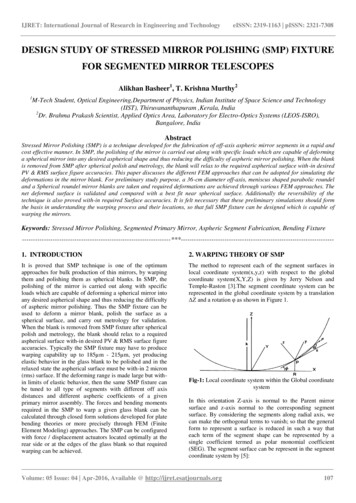
IJRET: International Journal of Research in Engineering and TechnologyeISSN: 2319-1163 pISSN: 2321-7308DESIGN STUDY OF STRESSED MIRROR POLISHING (SMP) FIXTUREFOR SEGMENTED MIRROR TELESCOPESAlikhan Basheer1, T. Krishna Murthy21M-Tech Student, Optical Engineering,Department of Physics, Indian Institute of Space Science and Technology(IIST), Thiruvananthapuram ,Kerala, India2Dr. Brahma Prakash Scientist, Applied Optics Area, Laboratory for Electro-Optics Systems (LEOS-ISRO),Bangalore, IndiaAbstractStressed Mirror Polishing (SMP) is a technique developed for the fabrication of off-axis aspheric mirror segments in a rapid andcost effective manner. In SMP, the polishing of the mirror is carried out along with specific loads which are capable of deforminga spherical mirror into any desired aspherical shape and thus reducing the difficulty of aspheric mirror polishing. When the blankis removed from SMP after spherical polish and metrology, the blank will relax to the required aspherical surface with-in desiredPV & RMS surface figure accuracies. This paper discusses the different FEM approaches that can be adopted for simulating thedeformations in the mirror blank. For preliminary study purpose, a 36-cm diameter off-axis, meniscus shaped parabolic roundeland a Spherical roundel mirror blanks are taken and required deformations are achieved through various FEM approaches. Thenet deformed surface is validated and compared with a best fit near spherical surface. Additionally the reversibility of thetechnique is also proved with-in required Surface accuracies. It is felt necessary that these preliminary simulations should formthe basis in understanding the warping process and their locations, so that full SMP fixture can be designed which is capable ofwarping the mirrors.Keywords: Stressed Mirror Polishing, Segmented Primary Mirror, Aspheric Segment Fabrication, Bending -----------------------------------------------1. INTRODUCTION2. WARPING THEORY OF SMPIt is proved that SMP technique is one of the optimumapproaches for bulk production of thin mirrors, by warpingthem and polishing them as spherical blanks. In SMP, thepolishing of the mirror is carried out along with specificloads which are capable of deforming a spherical mirror intoany desired aspherical shape and thus reducing the difficultyof aspheric mirror polishing. Thus the SMP fixture can beused to deform a mirror blank, polish the surface as aspherical surface, and carry out metrology for validation.When the blank is removed from SMP fixture after sphericalpolish and metrology, the blank should relax to a requiredaspherical surface with-in desired PV & RMS surface figureaccuracies. Typically the SMP fixture may have to producewarping capability up to 185µm - 215µm, yet producingelastic behavior in the glass blank to be polished and in therelaxed state the aspherical surface must be with-in 2 micron(rms) surface. If the deforming range is made large but within limits of elastic behavior, then the same SMP fixture canbe tuned to all type of segments with different off axisdistances and different aspheric coefficients of a givenprimary mirror assembly. The forces and bending momentsrequired in the SMP to warp a given glass blank can becalculated through closed form solutions developed for platebending theories or more precisely through FEM (FiniteElement Modeling) approaches. The SMP can be configuredwith force / displacement actuators located optimally at therear side or at the edges of the glass blank so that requiredwarping can be achieved.The method to represent each of the segment surfaces inlocal coordinate system(x,y,z) with respect to the globalcoordinate system(X,Y,Z) is given by Jerry Nelson andTemple-Raston [3].The segment coordinate system can berepresented in the global coordinate system by a translationΔZ and a rotation φ as shown in Figure 1.Fig-1: Local coordinate system within the Global coordinatesystemIn this orientation Z-axis is normal to the Parent mirrorsurface and z-axis normal to the corresponding segmentsurface. By considering the segments along radial axis, wecan make the orthogonal terms to vanish; so that the generalform to represent a surface is reduced in such a way thateach term of the segment shape can be represented by asingle coefficient termed as polar monomial coefficient(SEG). The segment surface can be represent in the segmentcoordinate system by [5]:Volume: 05 Issue: 04 Apr-2016, Available @ http://ijret.esatjournals.org107
IJRET: International Journal of Research in Engineering and Technologyz( , ) m cos n SEGm,nm n 0, m n : eventhe off-axis factor, and a the segment radius. The stressingcoefficients correspond to the amount of stress required toconvert a best fit spherical surface to the desired asphericshape. If kB is the best fit ROC of the blank in its stress-freestate, then the stressing coefficients are [5]:m,n 2,0 SEG a 2 2 K 2 k 4(1 K 2 ) 3 / 2 K 2 3/ 2 4(1 K ) 1/ 23 a K 1 ( K 1) 2 (4 K 2 ) 2 k 8(1 K 2 ) 3 2, 2 SEG 3,1SEG2 4, 0 4, 2SEG 1/ 2 a 4 K 2 2(1 3K ) (9 7 K ) K 2 (2 K ) K 2 4 3 k 16(1 K 2 ) 9 / 2 a 4 K 2 4 1 5K K 2 (6 5K ) k 3 64(1 K 2 ) 9 / 2( Power) 22 22 31STR 31SEG( Astigmatism)SEG In general, a m n m,n SEG O m 1 k (Coma) 33STR 33 40STR a 8k B 40 42STR 42SEG34SEG 44 STR 44 SEGa 4 8(1 K ) 24K 2 3K 2 4 (1 3K ) K 3 6 (2 K ) 3 k 64(1 K 2 ) 9 / 2 4, 4 SEG 20 STR a 2 2k B 20 SEGSTR a 3 K 2 3 1 ( K 1) 2k 2 8(1 K 2 ) 3 3,3 SEG SEG2akeISSN: 2319-1163 pISSN: 2321-7308(Trefoil)SEG(Spherical)(Sec. Astigmatism)(Quadrafoil)With the advancement in Stressed Mirror Polishing, it isproved that any desired surface shapes can be achieved bythe application of appropriate, continuously varying,tangential moments and shear (normal) forces only aroundthe perimeter of the part. No warping loads are required inthe interior of the part. The method for calculating thecontinuous moment and shear force densities requiredaround a circular segment perimeter to achieve the desiredwarping is given by Nelson et. al.[1,2]. Expressions to findout these Continuous moment density and shear forcedensity from the Polar monomial coefficients aresummarized in Table: 1.where K the conic constant, k the parent mirror paraxialROC, R the off-axis distance of the segment center, ε R/k,DescriptionTable 1. Polar Monomial Coefficient relationshipsPolar Monomial Coefficients Continuous moment densityContinuous shear force densityαmnMmnVmnPowerα20STR(2 D / a 2 )(1 ) 200Astigmatismα22STR(2 D / a 2 )(1 ) 222M 22 / aComaα31STR(2D / a2 )(3 ) 31 M 31 / aTrefoilPrimarySphericalSecondary Astigmatismα33STR(6 D / a 2 )(1 ) 333M 33 / aα40STR(4D / a2 )(3 ) 40 8M 40 / a(3 )α42STR(12D / a 2 ) 42( 1 )M 42 / aQuadrafoilα44STR(12D / a 2 )(1 ) 444M 44 / aFor a given no. of equally angular separated levers (N) withan angle of separation θL (L 1 to N), the discrete momentand shear force required at each lever can be calculated by[5]:2 aM L ( L ) M nm cos(n L ) for even m n, and m n 0Nshear force density respectively as given in Table 1. And Dis the plate stiffness modulus given by [1]:D Eh 3 12(1 2 )in which E and υ are Young’s modulus and Poisson’s ratiorespectively.mn2 aVL ( L ) Vnm cos(n L ) for even m n, and m n 0N mnwhere Mmn and Vmn are the continuous moment density andThe generation of bending moments and shear forces can besimultaneously achieved in a simple mechanism of a systemof weights, levers, and fulcra. If a Radial arm is bonded tothe outer cylindrical surface of the mirror blank (typically atVolume: 05 Issue: 04 Apr-2016, Available @ http://ijret.esatjournals.org108
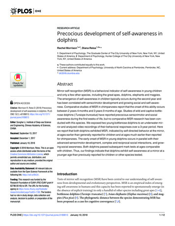
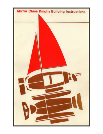
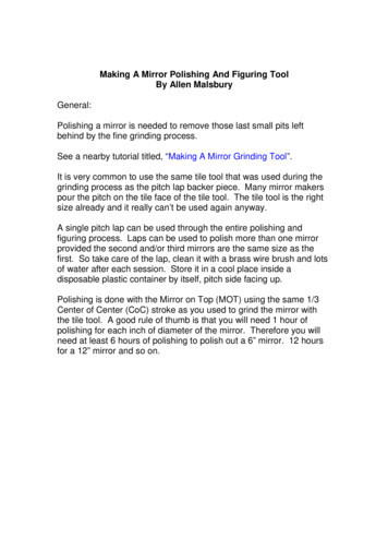
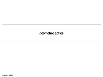
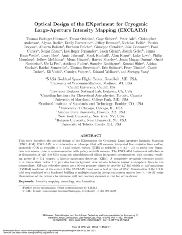
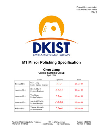
IJRET: International Journal of Research in Engineering and Technologythe middle of the edge thickness / or more appropriately inthe neutral axis of the blank) and forces are applied throughlevers on to the radial arm of the blank as shown in Fig. 2,they will produce both bending moments and shear forcessimultaneously by the mechanism. Multiple such levermechanism may be bonded to the mirror blank around themirror periphery at equi-spaced. In the present analysis andsimulations 24 units of such lever mechanism are found tobe optimum to deform the blank to given surface profileeither spherical to Parabolic or parabolic to Spherical.From the above Fig. 2, applying the equilibrium condition,the Shear Force & Bending Moment is calculated as:Shear Force, VL(θL) F1 F2Bending Moment, ML(θL) F1 r1 F2 r2ArmNo.Angle (θL)123456789101112130 15 30 45 60 75 90 105 120 135 150 165180ShearForce, 73-4.861.467.1111.0312.43eISSN: 2319-1163 pISSN: 2321-7308Using the above equilibrium condition the F1 & F2 arederived for the proposed geometry, r1 60mm & r2 300mmand are given in Table: 2Fig-2: Typical lever mechanism to produce bendingmoments and shear forces [4]Table 2. Computed Warping ForcesBendingWarpingWarpingMoment ML, Force(F1), Kg- Force(F2), 36.22-23.63-12.6-237.17-25.41958-12.9896F1, NF2, 7.2983. MIRROR CONFIGURATIONAs an initial theoretical bench mark study, a smaller sizeoff-axis primary mirror segment of Concave Parabola of360mm diameter with a paraxial Radius of Curvature (ROC)of 3688mm and a blank thickness of 25.4mm is taken up.The motivation for the selecting such smaller size blank isalso due to establish warping force computationmethodologies by closed form equations and bench mark theresults with the published results in a most valuable andpioneering research paper [2].Fig-4: Roundel made into On-axis by rotation about theROC pointFig-3: Roundel at the off axis distanceFurther by carrying out FEM Analysis with the obtainedclosed form results the deformed shapes can be simulatedand evaluated. In order to achieve desired shape asaccurately as possible with that that of theoretically requiredshape under that action of forces, several FEM simulationsare carried out with different load cases. The amount ofwarping required is based on the difference between thespherical surface to be polished into the deformed surfaceand the desired aspherical surface over the full aperture asgiven by Lubliner and Nelson [1]Volume: 05 Issue: 04 Apr-2016, Available @ http://ijret.esatjournals.org109
IJRET: International Journal of Research in Engineering and TechnologyeISSN: 2319-1163 pISSN: 2321-7308Fig-5: Deviation between parabola and its best fit sphericalThe objective of the study is to convert a best fit sphericalsurface to a near parabolic surface mirror by that applicationof either Stress or Displacement method using the actuators.The assumption is that, when the roundel is polished to sucha near best fit spherical along with the SMP with thosespecified forces, and when the roundel is removed fromSMP, we should get desired parabolic surface with inrequired accuracy. The amount of warping required is thedifference between best fit sphere and the desired parabolicaspheric surface. FEM based approach is consider forestablishing and validating the above assumptions.For the present study, basically two different approaches areadopted.1. Stress method: In this approach 24 lever system areconnected to the mirror and by the application of eitherbending moment and shear force along with a centralsupport, the mirror is warped to desired shape withdifferent load cases.2. Displacement method: In this approach, the actuatorsconnected at the bottom of the mirror are displaced bythe required amount and this displacement causesdeformations on the mirror as actuation.4. FEM ANALYSIS4.1 FEM Analysis Using Displacement MethodLoad case 1: Effect of applying Displacement method onactuatorsIn this particular model, the rear side of the mirror blank isconnected with a 24 equally spaced stainless steel actuatorswhich are in turn fixed at the bottom with all six degrees offreedom. Additionally a central support is also given to themirror blank by an actuator for structural rigidity of themodel. From the front surface data of best fit spherical andparabolic surface acquired from the model, the deviationrequired to transform this best fit spherical to parabolicsurface is calculated, and applying the force required toachieve this deviation on the actuators, the desired deviationand finally the desired surface is expectedFig-6: Application of Loads and Boundary ConditionsFig-7: Deformation of actuators due to the application ofload4.2 FEM Analysis Using Stress MethodLoad case 2: Effect of Bending Moment & CentralsupportThe Bending Moments as computed from closed formequations and given in Table: 2 are applied through 24 unitsof lever assemblies around periphery of the mirror and areshown in Fig.7. As shown in the above FE model, the leversare simulated as beam elements of SS material. As pergeometry, each lever length is taken as 300mm projectingoutward from mirror blank outer periphery. Forces actingperpendicular to radial arm and acting along gravity vectorviz. "F1" is applied at 60mm from the mirror and similarly"F2" is applied at 300mm i.e. outer end of the lever. Tosimulate the bonding of the lever at the mirror edge, MultiPoint Constraint (MPC) mechanism is used where ninenodes on the periphery of the mirror covering an areaapproximately 150mm sq. are linked to the master node ofthe radial arm.The vertical Force arms of length 30mm are linked to theradial arm as shown in Fig.6. The warping forces "F1" &"F2" given in Table: 2 together will produce the Bendingmovements on to the mirror blank according to the platebending theory. The forces "F1" & "F2" are that for thedeformation of a spherical to anti-parabola on SMP so thatafter polishing a sphere in the deformed surface andremoving the loads; required parabolic surface is obtained.However, in our present simulations, the objective is todeform spherical surface and compares the deformed surfacedirectly with that of required surface (Parabolic) and viceversa. Hence the forces computed in Table: 2 are reversed insign keeping the magnitude same. This facilitates direct oneto one comparison of the deformed surface vs desiredsurface.Volume: 05 Issue: 04 Apr-2016, Available @ http://ijret.esatjournals.org110
IJRET: International Journal of Research in Engineering and TechnologyeISSN: 2319-1163 pISSN: 2321-73084.2 FEM Analysis To Prove Reversibility of SMPFig-8: The warping modelFig-9: The warping model with Loads appliedLoad case 3: Effect of Shear Force & Central SupportThe shear forces as computed from closed form equationsand given in Table: 2 are applied through 24 axial armslinked to the radial arm in two different methods. In onemethod the application of force is at the interface junction ofthe radial arm but without radial arms as shown in Fig. 8.and in the other one, the application of force is at the rearedge of the mirror blank as shown in Fig. 9. As explained,the shear forces calculated in the Table: 2. are for deformingthe spherical surface to anti-parabola on SMP so that afterpolishing a sphere in the deformed surface and removing theloads, the required parabolic surface is obtained.Fig-10: Application of Shear Forces on cylindrical rimFig-11: Application of Shear Forces on rear sideAfter finding out the optimum approach for the SMP interms of surface RMS, the same model has taken up toprove the reversibility of the technique.Exercise 1: Study of deformation of a spherical blank intoparabolic.Exercise 2: Study of deformation of a spherical blank intoanti-parabolic.Exercise 3: Study of deformation of a parabolic blank intospherical.In Ex: 1, a spherical blank is deformed in to a parabolicsurface and the surface RMS in terms of Fringe ZernikeCoefficients is noted down. After that, the same sphericalblank is deformed into an anti-parabola by simply reversingthe direction of the applied shear forces and the surfaceRMS is noted down. This RMS need not to be same as theprevious one, because, one is deformed into entirelyopposite curvature shape, so that variation should be there inthe results. Next in Ex: 3, a parabolic mirror is taken up anddeformed into a spherical by reversing the direction of shearforce in Exercise: 1, and the surface RMS is noted down.This result is expected to be match very close to the Ex: 1.4.3 FEM analysis to modify the resultsAfter obtaining the optimum approach, by examining thevariation in the deviations achieved, the shear forces can bemodified at required locations to further modification of theresults. It can be also achieved by reducing certainaberration terms like astigmatism. So an exercise has donein order find out the effect of reducing the astigmatic termby gradual modification of shear force at 90 and 270 region alone. For this purpose the Zernike coefficients arefound out by increasing and decreasing the Shear force by10%. It is observed that an 8% improvement in the surfaceRMS by the reduction of shear force.Table 3: Surface RMS for the Modified shear forceObtained Zernike CoefficientsNormalIncr. ShearDecr. ShearNAMEShear ForceForceForcePiston21.31635521 22.86467943 20.05157003Tilt x252.086607 255.8882068 250.5923036Tilt y-0.00113314 -0.00014837 -0.0001893Focus16.9461829 18.12255164 15.89161284Astig x-15.5533248 -17.6828588 -13.5865425Astig y-0.00126170.001000240.0009485Coma x13.64603523 13.77238198 13.48801768Coma y-0.00129461 -0.00012469 -0.00010839Pri. sph-3.08825752-3.317479-2.90813654Trefoil x0.03863643-0.11510830.23183067Trefoil y-0.00296570.001149410.00115775Sec. Astig x0.508366620.592223380.45830571Sec. Astig y -0.00260173 -0.00000474 0.00000833Sec. Coma x -6.64346892 -6.58477973 -6.44864238Sec. Coma y -0.00086331 -0.00007474 0.00000234Sec. Sph0.844801240.878335750.77203126Overall5.37 µm5.79 µm4.93 µmRMSVolume: 05 Issue: 04 Apr-2016, Available @ http://ijret.esatjournals.org111
IJRET: International Journal of Research in Engineering and TechnologyeISSN: 2319-1163 pISSN: 2321-73085. RESULTS5.1 Results of Loadcases to Find the Optimum SMPApproachFig-17: Spherical to anti-parabola (5.476µm)Fig-12: LC: 1- (7.711µm)Fig-18: Parabola to Spherical (5.6826µm)Fig-13: LC: 2- (11.866 µm)6. CONCLUSIONFig-14: LC: 3.a- (5.6824 µm)Fig-15: LC: 3.b- (5.174µm)Front Surface Deformation on the Spherical Mirror due todifferent load cases given in microns.This paper describes the study on Opto-mechanical designand FE analysis for force calculation. The purpose of thework is to simulate the deformed surface of parabola afterforcing it and comparing with an ideal best fit sphericalusing different approach and to find out an optimum one. Among the all loading conditions, the Load case withshear force and central support is found to be theoptimum approach. The surface figure of 5.18 microns is achieved throughthe shear force and central support alone. With same loads and boundary conditions, the RMSsurface figure after the deformation of spherical toparabola and parabola to spherical is found to ), and spherical to anti-parabola is 5.476 µm,all of these prove the reversibility of the SMP. The same model for various thicknesses is re-modeledand analyzed by calculating the forces, to validate thecalculations. By proper modification of the applied shear force, thesurface figure is improved from 5.37 microns to 4.9microns. So further modification is also possible by thecorrection of selected aberrations.5.2 Results of Exercises To Prove Reversibility of7. ACKNOWLEDGEMENTSSMPThe authors gratefully acknowledge the support of IndianInstitute of Space Science and Technology (IIST),Thiruvananthapuram and Laboratory for Electro-OpticsSystems (LEOS-ISRO), Bangalore.REFERENCESFig-16: Spherical to Parabola (5.6824µm)[1] Lubliner and Nelson, "Stressed Mirror Polishing. 1: Atechnique for producing non-axisymmetric mirrors", TMTReport No. 61. [Applied Optics, Vol. 19, No. 14, 15 July1980]. (Keck Observatory Report No. 21)Volume: 05 Issue: 04 Apr-2016, Available @ http://ijret.esatjournals.org112
IJRET: International Journal of Research in Engineering and TechnologyeISSN: 2319-1163 pISSN: 2321-7308[2] Nelson, Gabor, Hunt, Lubliner, Mast, "Stressed MirrorPolishing. 2: Fabrication of an off-axis section of aparaboloid", TMT Report No. 62. [Applied Optics, Vol. 19,No. 14, 15 July 1980]. (Keck Observatory Report No. 22)[3] Nelson and Temple-Raston, "The Off-Axis Expansionof Conic Surfaces", UC TMT (Keck) Report No. 91,November 1982[4] Terry S. Mast and Jerry E. Nelson [1985]. Fabrication ofKeck off-axis mirror segments. SPIE Vol. 542.[5] Stephen F. Sporer, “TMT - Stressed Mirror PolishingFixture Study”, Tinsley Laboratories, Division of SSGPrecision Optronics,4040 Lakeside Drive, Richmond, CA94806, USA[6] Paul. R. Yoder, Jr. “Opto-Mechanical Systems Design”Third Edition, 2006, SPIE Press.[7] Anees Ahmed, “Handbook of Opto-mechanicalEngineering” 1997 CRC Press.BIOGRAPHIESAlikhan Basheer received the B-Techdegree in Electronics and CommunicationEngineering from the Mahatma GandhiUniversity, Kottayam, India, in 2012 andthe M-Tech degree in Optical Engineeringfrom the Indian Institute of Space ScienceandTechnology(IIST),Thiruvananthapuram, India, in 2015.His research is focusedon Opto-mechanical design and analysis of mechanicalfixtures for TMT primary mirror segments. His research alsoincludes the metrology study for the TMT Primary mirrors.KrishnaMurthy T received B.Sc. degree inphysics from Osmania Univeristy in 1974and the M.Sc (Tech) Engineering Physicsdegree (with specialization in Modern andApplied Optics) from NIT Warangal(Kakatiya University), in 1977. With anexperience of 30 years in Indian SpaceResearch Organization (ISRO), he is currently teachingOpto Mechanical Engineering & Adaptive Optics to MastersDegree students of Indian Institute of Space Science andTechnology (IIST), Thiruvananthapuram since 2012.Volume: 05 Issue: 04 Apr-2016, Available @ http://ijret.esatjournals.org113
Stressed Mirror Polishing (SMP) is a technique developed for the fabrication of off-axis aspheric mirror segments in a rapid and cost effective manner. In SMP, the polishing of the mirror is carried out