Transcription
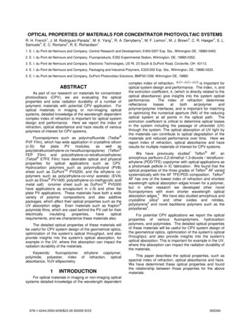
Optical Design of the EXperiment for CryogenicLarge-Aperture Intensity Mapping (EXCLAIM)Thomas Essinger-Hilemana , Trevor Oxholmb , Gage Siebertb , Peter Adec , ChristopherAndersona , Alyssa Barlisa , Emily Barrentinea , Jeffrey Beemand , Nicholas Bellisa , PatrickBreyssee , Alberto Bolattof , Berhanu Bulchaa , Giuseppe Cataldoa , Jake Connorsa,g , PaulCurseya , Negar Ehsana , Lee-Roger Fernandeza , Jason Glenna , Joseph Golech , JamesHays-Wehlea , Larry Hessa , Amir Jahromia , Mark Kimballa , Alan Koguta , Luke Lowea , PhilipMauskopfi , Jeffrey McMahonh , Mona Mirzaeia , Harvey Moseleya , Jonas Mugge-Duruma , OmidNorooziana , Ue-Li Pene , Anthony Pullenj , Samelys Rodrigueza , Konrad Shirea , AdrianSinclairi , Rachel Somervillek , Thomas Stevensona , Eric Switzera , Peter Timbieb , CaroleTuckerc , Eli Visball , Carolyn Volperte , Edward Wollacka , and Shengqi YangjaNASA Goddard Space Flight Center, Greenbelt, MD, USAbUniversity of Wisconsin-Madison, Madison, WI, USAcCardiff University, Cardiff, UKdLawrence Berkeley National Lab, Berkeley, CA, USAeCanadian Institute for Theoretical Astrophysics, Toronto, CanadafUniversity of Maryland, College Park, MD, USAgNational Institute of Standards and Technology, Boulder, CO, USAhUniversity of Chicago, Chicago, IL, USAiArizona State University, Phoenix, AZ, USAjNew York University, New York, NY, USAkRutgers University, New Brunswick, NJ, USAlUniversity of Toledo, Toledo, OH, USAABSTRACTThis work describes the optical design of the EXperiment for Cryogenic Large-Aperture Intensity Mapping(EXCLAIM). EXCLAIM is a balloon-borne telescope that will measure integrated line emission from carbonmonoxide (CO) at redshifts z 1 and ionized carbon ([CII]) at redshifts z 2.5 3.5 to probe star formation over cosmic time in cross-correlation with galaxy redshift surveys. The EXCLAIM instrument will observeat frequencies of 420–540 GHz using six microfabricated silicon integrated spectrometers with spectral resolving power R 512 coupled to kinetic inductance detectors (KIDs). A completely cryogenic telescope cooledto a temperature below 5 K provides low-background observations between narrow atmospheric lines in thestratosphere. Off-axis reflective optics use a 90-cm primary mirror to provide 4.20 full-width at half-maximum(FWHM) resolution at the center of the EXCLAIM band over a field of view of 22.50 . Illumination of the 1.7 Kcold stop combined with blackened baffling at multiple places in the optical system ensures low ( 40 dB) edgeillumination of the primary to minimize spill onto warmer elements at the top of the dewar.Keywords: Intensity mapping, cosmology, star formationFurther author information: (Send correspondence to T.E.H.)T.E.H.: E-mail: tom.essinger-hileman@nasa.gov, Telephone: 1 301 286 3693Millimeter, Submillimeter, and Far-Infrared Detectors and Instrumentation for Astronomy X,edited by Jonas Zmuidzinas, Jian-Rong Gao, Proc. of SPIE Vol. 11453, 114530H 2020 SPIE · CCC code: 0277-786X/20/ 21 · doi: 10.1117/12.2576254Proc. of SPIE Vol. 11453 114530H-1Downloaded From: eedings-of-spie on 22 Jan 2021Terms of Use: https://www.spiedigitallibrary.org/terms-of-use
1. INTRODUCTIONStar formation reached a peak at a redshift z 2 and has subsequently declined despite the continued growth ofdark matter haloes.1, 2 Galactic feedback mechanisms are commonly thought to be the cause of this decline, butfurther observations are required to disentangle the effects. Line intensity mapping (LIM), in which integratedline emission is mapped at low angular resolution, offers a complementary approach to traditional galaxy surveyswith several advantages. LIM creates a map of all emission in a given line free from selection bias. Furthermore,the low angular resolution required enables large survey areas to be efficiently mapped with modest requirementson the aperture size. Simulations3 show tensions with measurements of CO in individual galaxies, motivating ablind, complete survey over a large area.The EXperiment for Cryogenic Large-Aperture Intensity Mapping (EXCLAIM) is a balloon-borne cryogenictelescope that will measure diffuse emission from several carbon monoxide (CO) J (J 1) rotational lines(νCO,J 115J GHz) for J 4 7 at redshifts z 1 and singly-ionized carbon ([CII]) in the 158.7 µm(ν[CII] 1.889 THz) line at redshifts z 2.5 3.5. The EXCLAIM survey will consist of a 320 deg2 extragalactic(EG) survey and several 100 deg2 galactic plane (GP) survey regions. The GP survey will map CO(4-3) andneutral carbon ([CI]). The [CI] survey will assess the CO-H2 ratio to inform the higher-redshift survey, as [CI]traces H2 in regions where CO is photodissociated.4, 5 The EG survey will be cross-correlated with galaxies andquasars in the Baryon Oscillation Spectroscopic Survey (BOSS)6 to map EXCLAIM observations in redshiftspace.EXCLAIM consists of a completely cryogenic telescope in an open liquid-helium bucket dewar with a coldinner volume approximately 1.5 m in diameter and 2.0 m deep. At target float altitudes above 27 km, the ambientpressure of less than 10 Torr pumps on the helium bath, lowering its temperature below its superfluid transitionto approximately 1.7 K. Superfluid helium pumps demonstrated on the ARCADE2 and PIPER payloads7–9efficiently cool the full optical chain to below 5 K.The EXCLAIM optics consist of a two-mirror, off-axis Gregorian telescope with a 90-cm parabolic primarymirror and a 10-cm parabolic secondary mirror. A folding flat between the primary and secondary allows thetelescope to fit within the dewar volume. Baffling around the intermediate focus controls stray light and housesan aerogel scattering filter for rejection of IR radiation.10 The rays are collimated after the secondary mirrorand pass through a meta-material anti-reflection (AR) coated silicon vacuum window into the receiver cryostat.The receiver houses additional stray-light baffling, aerogel scattering and band-defining metal-mesh filters,11 anAR-coated silicon lens,12 and six integrated silicon spectrometers (µ-Spec).13–15The µ-Spec spectrometers combine all the elements of a traditional diffraction-grating spectrometer in acompact package using planar transmission lines on a silicon chip. The grating is replaced by a niobium microstripdelay line network that launches signals into a 2D parallel-plate waveguide region with emitting and receivingfeeds arranged in a Rowland configuration. EXCLAIM will operate at the second grating order selected by anon-chip filter along with the free-space band-defining filters. A set of 355 microwave kinetic inductance detectors(MKIDs) made from 20-nm-thick aluminum (Al) half-wave resonators will detect the signal. A dipole slot antennacoupled to a hyper-hemispherical AR-coated silicon lenslet forms the spectrometer beam and couples the lightto the on-chip circuitry. The combination of quasi-optical metal-mesh filters, on-chip filters, and spectrometerdesign defines the EXCLAIM observing band of 420–540 GHz. The MKID arrays for the six spectrometers use amicrowave multiplexing readout scheme with heritage from The Next Generation Balloon-borne Large ApertureSubmillimeter Telescope (BLAST-TNG)16 and the Far Infrared Observatory Mounted on a Pointed Balloon(OLIMPO).17The EXCLAIM gondola design, attitude determination and control system, and flight electronics are basedon those of PIPER with modest modifications and improvements. EXCLAIM will observe at constant elevationwith scans in azimuth between 5 and 10 wide to map strips on the sky. A primary target is Sloan Stripe 82;however, the details of the scan strategy will depend upon the availability of sources for a given flight locationand time of year.For more information on the EXCLAIM mission, see Cataldo et al. in these proceedings.18 For details ofthe spectrometer design and fabrication, see Mirzaei et al. in these proceedings.19 This paper is organizedas follows. Section 2 describes the optical design requirements, system layout, and key optical components.Proc. of SPIE Vol. 11453 114530H-2Downloaded From: eedings-of-spie on 22 Jan 2021Terms of Use: https://www.spiedigitallibrary.org/terms-of-use
104Photon power per channel, through stopPower (fW)10310210110010-1420440460480500Frequency (GHz)Cryogenic Telescope Atmosphere5 K blackbody520540250 K blackbodyFigure 1: Estimated optical power (defined as passing through the stop to the spectrometer) due to the atmosphere and a cold telescope compared with blackbodies at 10 K, and 250 K for reference. The requirementon warm spill of 40 dB reduces the 250 K blackbody load below that of the estimated power from theatmosphere. The telescope temperature requirement of 5 K ensures that the reflective optics with pessimisticemissivity of 10% do not exceed the loading from the atmosphere in the darkest channels.Section 3 describes the performance of the optical system as modeled with ray-tracing software. Section 4describes physical-optics analysis of diffraction in the system. We conclude in Section 5.2. OPTICAL DESIGNThe EXCLAIM optical design is unique in several ways. As EXCLAIM is not taking an instantaneous imageand the map is filled in by multiple observations with different detectors in each pixel, the optical design hasrelatively loose requirements on optical aberrations. There are, however, very stringent requirements on totalexcess loading on the detectors, since modest spill onto warm elements will significantly degrade performance inthe darkest spectral channels. As shown in Figure. 1, even modest illumination at the 40 dB level of a 300 Ksurface is comparable to the power in the darkest channels. The EXCLAIM optical design aims to limit straylight through the overall system architecture, combined with baffling in key places.In this section, we describe the requirements on the optical system that flow down from EXCLAIM scienceand mission objectives (Section 2.1); give an overview of the optical design that meets those requirements(Section 2.2); and describe the design of key optical components, including the silicon superfluid-tight receiverwindow, silicon lens, coupling to the spectrometer wafer via a dipole antenna and hyper-hemispherical siliconlenslet, IR-blocking aerogel scattering filters, metal-mesh band-defining filters, and in-flight calibration source(Section 2.3).2.1 Requirements OverviewThe EXCLAIM optical design needs to satisfy a number of mechanical, optical, cryogenic, and integration andtest (I&T) requirements. Primary requirements on the optical design are:1. The telescope shall fit within a cylindrical volume approximately 1.2 m in diameter and 1.5 m deep. Thiscorresponds to the usable volume within a bucket dewar sized such that the payload fits within mass limitsset by balloon lift capabilities of 3400 kg. The bucket dewar is the same size as has been demonstratedfor the PIPER payload. See Figure 2 for more details on the payload mechanical design.Proc. of SPIE Vol. 11453 114530H-3Downloaded From: eedings-of-spie on 22 Jan 2021Terms of Use: https://www.spiedigitallibrary.org/terms-of-use
SecondaryMirrorAerogel Filter152 cmPrimaryMirrorSecondaryMirrorAerogel FilterLP and HPFiltersFoldingFlatIntermediateFocus & BafflingVacuum WindowLensIn-Situ CalibratorFocal PlaneFigure 2: Overview of the EXCLAIM optics within the open helium bucket dewar with an expanded view of thereceiver, showing the major optical elements, including the mirrors, silicon lens, silicon vacuum window, filters,and in-situ calibrator. Note that the calibrator is tilted into the page in this figure, such that it is in the sidelobesof the lenslet beams.2. The angular resolution shall be 70 to allow measurement of physical scales down to approximately 200 kpc(modes k & 5 h/Mpc).3. The design shall maintain total root-mean-squared (RMS) wave front error (WFE) below 0.075 waves atthe center of the band, 480 GHz. This corresponds to a Strehl ratio greater than 0.80.4. The instantaneous field of view (FOV) of the telescope shall be between 12.50 and 250 . This allows efficientmapping of the target observation areas given the angular resolution.5. Excess loading from stray light on each KID shall be below the expected power in the darkest spectrometerchannels, 0.1 fW defined at the receiver cold stop, to ensure nearly background limited performanceacross the band.6. The optical design shall provide for a collimated region within the receiver volume with a 3:1 aspect ratiofor effective magnetic shielding, as the KIDs are susceptible to magnetic fields.7. The telescope shall operate at 5 K to ensure that loading from the reflective optics, assuming a pessimistic10% total emissivity, does not exceed 0.1 fW, requiring that warm alignment translates to alignment uponcooling.8. The receiver shall be placed vertically under the primary mirror to allow the receiver to be tested in a liquidhelium dewar prior to integration with the telescope and to allow the telescope to be aligned separatelyfrom and before integration with the receiver.9. The design shall provide a means for rapid optical modulation in the event that the stability of the detectordata is not sufficient. MKIDs and the associated readout system can have excess low-frequency, or 1/f ,noise due to two-level systems that would lead to striping in the maps. The primary science signal bandfor EXCLAIM is approximately 5–25 Hz, based on the current scan strategy. This requirement ensuresProc. of SPIE Vol. 11453 114530H-4Downloaded From: eedings-of-spie on 22 Jan 2021Terms of Use: https://www.spiedigitallibrary.org/terms-of-use
that rapid modulation could be implemented if required after laboratory testing or the engineering flightto mitigate excess 1/f noise.These primary requirements lead to a series of derived requirements on the optical design. Key derivedrequirements are:10. The telescope shall have a physical aperture of 90 cm and projected aperture of 76 cm. This fulfills theangular resolution requirement while fitting within the allowable volume and allowing under-illuminationof the primary mirror to reduce ambient-temperature spill. See Sec. 4 for more discussion of angularresolution given realistic Gaussian beam truncation.11. The reflective telescope shall be f /2 to stay within the allowable volume, while producing a collimatedregion inside the receiver of reasonable diameter, 10 cm, to provide the required 3:1 aspect ratio formagnetic shielding.12. The receiver shall house a 1.8 K cold aperture stop that truncates the beams from the on-chip spectrometerlenslets at 15 dB at all frequencies within the EXCLAIM band to maintain low edge illumination onthe primary mirror for stray light reduction. Given the lenslet beam width (See Sec. 2.2), this requiresthat the system be f /3.2 after the silicon lens.13. Stray light spill onto ambient temperature ( 100 K) surfaces, including those behind the primary mirror,around the dewar aperture, and the balloon, shall be less than 40 dB. This ensures that excess loadingfrom warm spill stays below 0.1 fW.Though not a strict requirement, the design also attempted to reduce the potential for optical cavities tocreate fringing within the EXCLAIM band and multiple images of objects on the sky from ghosting. As aspectrometer, EXCLAIM is more prone to this than broadband imaging experiments. Given the design spectralresolving power, R 512, at the center of the EXCLAIM band, ν 470 GHz, each MKID channel is sensitive toa bandwidth of approximately ν 0.9 GHz. This leads to a coherence length, c/ ν, of approximately 33 cm,which is on the order of the size of the optics tube within the receiver. To mitigate possible cavities formedwithin the receiver optics tube, the silicon lens and filters were tilted with respect to the chief ray by 3 and 2 ,respectively. Different tilt directions were used for each optical element to further reduce cavity modes.2.2 Optical LayoutTo meet the requirements set out above, the EXCLAIM optical design shown in Figure 3 uses a large, 90 cm,off-axis parabolic primary mirror that is 76 cm in projection. This primary mirror is highly under-illuminatedto reduce beam spill around the edges of the primary, which could fall onto warm surfaces. The effective focallength of the primary mirror is set to 155 cm to allow the rays to come to an intermediate focus within thedewar volume on the way to the secondary mirror. A folding flat 30 cm in diameter redirects the rays so thatthe optical system can fit within the dewar and to allow the secondary mirror to be under the primary mirror,as required by the integration and test sequence.A more complicated design including a hyperbolic mirror in place of the folding flat in a Mizugutch-Dragoneconfiguration20, 21 was initially considered; however, the performance of the simpler design outlined here wasfound to be sufficient given the reasonably loose requirements on optical aberrations and cross polarization forEXCLAIM. Having a folding flat in place of a shaped mirror significantly reduces system complexity and mirrorfabrication costs with modest loss of optical quality.The intermediate focus is important for stray-light control, allowing the secondary mirror and receiver windowto be placed entirely within a baffled enclosure. In this enclosure and in the receiver optics tube, baffle ringsare blackened with Epotek 377 epoxy loaded with silica and graphite powders.22 The thickness of this coatingis chosen to be 2 mm to provide a balance between absorption at frequencies below the EXCLAIM band andmass of the coating. The thickness and shape of the coating will be controlled using molds following theprocedures described in Ref. 23. This intermediate focus also provides a natural place for a chopper if rapidoptical modulation is deemed necessary after an engineering flight.Proc. of SPIE Vol. 11453 114530H-5Downloaded From: eedings-of-spie on 22 Jan 2021Terms of Use: https://www.spiedigitallibrary.org/terms-of-use
Figure 3: Left: Ray trace of EXCLAIM optics using Zemax OpticStudio for two pixels at the top and bottomof the focal plane. Right: Strehl ratio at high end of the EXCLAIM band, 540 GHz, over the field of view, whichfor EXCLAIM is 16.10 , or 0.14 . The nominal design performance has Strehl ratio 0.94 across the field ofview. Strehl ratio performance is better at lower frequencies within the band.After the intermediate focus, a parabolic secondary mirror with an effective focal length of 19.5 cm collimatesthe beam as it enters the receiver through the AR-coated silicon vacuum window. The collimated region is 23 cmlong and serves multiple purposes. The initial driving requirement was to allow for magnetic shielding with afavorable 3:1 aspect ratio to be placed around the spectrometers, as the MKIDs are sensitive to magnetic fields.Note that the magnetic shield diameter of 14 cm is necessarily larger than the diameter of the optical baffling toallow room for mechanical clearance between the magnetic shield and copper optics tube, as well as for mountingflanges for the lens, filters, and the optics tube as a whole. This means that the collimated region and focallength of the lens, at 24 cm, combine to provide an approximately 3:1 aspect ratio for the magnetic shielding.Optically, the collimated region affords an extended baffled section for stray light control and a natural locationfor free-space filters.The receiver houses a blackened 7.6 cm cold aperture stop and a plano-convex silicon lens with a focal lengthof 24 cm to couple light onto the hyper-hemispherical lenslets of the spectrometers. As noted above, the siliconlens is tilted by 3 to reduce cavity modes and ghosting within the receiver. The planar surface of the tiltedlens faces toward the focal plane. The 4-mm diameter lenslets provide an approximately Gaussian beam with afull-width at half maximum (FWHM) of 8.0 (mean of E- and H-plane) at the center of the EXCLAIM band,470 GHz. The corresponding 15 dB angle for the beams at that frequency is 15.8 full angle. At the lowfrequency edge of the band at 420 GHz, the FWHM and 15 dB half angle are 9.0 and 18.0 , respectively. Asthe beams are broadest for the lowest frequency within the band, requiring the cold stop to truncate at 15 dBacross the full band translates into a 7.6-cm cold stop diameter given the 24-cm lens focal length, leading to anoptical speed of f /3.2 at the focal plane.The six 4.0-mm diameter lenslets are equally spaced around a 9.0-mm circle (4.5 mm between neighboringlenslets) to give adequate space for the supporting silicon wafer and reasonable fabrication tolerances on thecopper detector package. With the lenslet separation set, the field of view of the telescope is determined by theplate scale, which specifies the ratio between distance within the focal plane and angular separation on the sky.For this design, the plate scale is given by Fs /(F Fp ), where Fp , Fs , and F are the focal lengths of the primarymirror, secondary mirror, and lens, respectively. Given the values above, the plate scale of the system is 1.80 /mm,Proc. of SPIE Vol. 11453 114530H-6Downloaded From: eedings-of-spie on 22 Jan 2021Terms of Use: https://www.spiedigitallibrary.org/terms-of-use
Normalized beam1.01.0E-plane HFSSE-plane FitH-plane HFSSH-plane Fit0.80.60.8E-plane Gaussian Fit FWHM: 7.7H-plane Gaussian Fit FWHM: 8.0Beam Ellipticity: 3.5 %0.40.20.60.40.03Residuals [%]Norm. BeamNorm. Cumulative Solid Angle0.2E-plane fit residualsH-plane fit residuals30.0 2.5 5.0 7.5 10.0 12.5 15.0 17.5 20.0Angle (deg)0.0Stop efficiency: 74 % for stop half-angle 9 deg0255075100Theta (deg)125150175Figure 4: Left: The beam simulated using Ansoft HFSS for the EXCLAIM spectrometer on-chip silicon lensletcoupled antenna. In the upper panel, the E-plane (H-plane) beam from HFSS is shown in solid blue (red) with aGaussian fit shown in the blue (red) dashed lines. Residuals from the fit, shown in the lower panel, are below 3%of the beam peak. Right: Normalized beam in blue and cumulative solid angle in orange from HFSS simulations.The aperture efficiency for the EXCLAIM aperture stop half-angle of 9 is 74%.corresponding to a field of view for the 9-mm focal plane of 16.10 , well within the range of Requirement 4.2.3 Optical ComponentsIn this section we briefly summarize key design and manufacturing considerations for EXCLAIM optical components, including the aluminum primary, folding flat, and secondary mirrors; the silicon lens and receiver window,band-defining and IR blocking filters, and in-situ calibrator.2.3.1 Mirror ManufacturingThe primary, folding flat, and secondary mirrors will be computer numerical control (CNC) machined out ofmonolithic pieces of aluminum. The surface figure of the mirrors is required to be within 25 µm of nominal,corresponding to RMS phase error of 0.020 waves at 470 GHz. It is assumed that the folding flat will be able toachieve considerably better surface figure. The contributions of the primary and secondary mirror surface figureerrors add together in quadrature to give total mirror surface figure wavefront error less than 0.028 waves.The RMS surface roughness of the mirrors is required to be below 2 µm, so that scattering from the mirrorsonto warm surfaces stays well below 40 dB. A surface roughness gives rise to a gain degradation factor of2α e (4π /λ)(1)where is the RMS surface roughness and λ is the observing wavelength. Requiring this term to be below 43 dB corresponds to an RMS surface finish of approximately 0.4 µm. The required surface figure is achievableif care is taken in the CNC machining process. Post-machining polishing will bring the surface finish within therequirement.2.3.2 Silicon Lens and Receiver WindowThe receiver houses both a lens and a vacuum window, which will be made of silicon with a metamaterial AR coating. A single-layer AR coating produced by a custom dicing saw on a computer-controlled XY gantry system12provides sufficient performance over the EXCLAIM band, as shown in Fig. 5; however, a tapered profile createdusing a laser-cutting system provides higher performance and is the baseline for EXCLAIM. Silicon lenses havebeen demonstrated on a number of instruments. EXCLAIM will be demonstrating a superfluid silicon vacuumProc. of SPIE Vol. 11453 114530H-7Downloaded From: eedings-of-spie on 22 Jan 2021Terms of Use: https://www.spiedigitallibrary.org/terms-of-use
1.00.6Quasioptical low-pass filterQuasioptical high-pass filterOn-chip order-choosing filterCombined filters0.40.20.0200400600Freq (GHz)8001000Reflection (%)Transmission0.83.53.02.52.01.51.00.50.0Diced Single LayerLaser Cut Tapered400425450475 500Freq (GHz)525550Figure 5: Left: Compilation of quasioptical, metal-mesh low-pass and high-pass filters (housed in the receiveroptics tube) and on-chip order-choosing filter planned for EXCLAIM, along with the estimated total transmissionspectrum through the set of filters. Right: Modeled performance of the baseline laser-cut tapered AR coatingcompared with established single-layer diced AR coating for the EXCLAIM silicon lens and window.window for the first time. The window must maintain high in-band transmission, while providing a superfluidtight vacuum seal. PIPER has previously demonstrated a quartz window with a superfluid-tight indium sealand a polytetrafluoroethylene AR coating;24 however, the measured quartz loss at EXCLAIM frequencies issignificant, leading to the choice of silicon as an alternative.2.3.3 FiltersEXCLAIM requires free-space filters for IR rejection and band definition. Two IR-blocking filters will be usedin the EXCLAIM system, one near the intermediate focus and the other as the first element after the vacuumwindow within the receiver volume. These IR blocking filters will be composed of diamond scattering particlesembedded in a polyimide aerogel substrate with low index of refraction and low loss.10 Particle size and densitywill be tuned to produce a lowpass filter with a cutoff frequency 1 THz.Two free-space filters for band definition will be placed between the IR blocking filter and the aperture stopwithin the receiver optics tube and will be composed of a heat-pressed stack of metal-mesh filters on polypropylenefilm with dielectric spacers.11 A combination of a highpass and lowpass filter, used in conjunction with an ordersorting filter on the spectrometer wafer, will reject radiation immediately above and below the EXCLAIM band.Fig. 5 shows the modeled transmission spectra of the band-defining filters along with the resultant compositespectrum.2.3.4 In-Situ CalibratorThe EXCLAIM receiver will incorporate an in-situ calibration source for in-flight characterization of spectrometerresponse, uniformity, and time-varying responsivity. The source is a reverse bolometer of similar design to thatused by the Herschel SPIRE instrument.25 It consists of a sapphire square with an integrated heater thermallyisolated from the bath stage using nylon threads. This reverse bolometer is mounted in a copper ring and placedwithin a bead-blasted integrating cavity. A small aperture in the cavity couples power out to the spectrometers.The calibrator is placed just below and outside the lens to couple into the sidelobes of the on-chip spectrometerlenslet beams.3. DESIGN PERFORMANCE, TOLERANCING, AND ALIGNMENTThe EXCLAIM optical design was laid out and optimized using Zemax OpticStudio in sequential mode. Oncethe basic design described in Sec. 2 was determined, it was optimized to minimize WFE, allowing the lens radiusProc. of SPIE Vol. 11453 114530H-8Downloaded From: eedings-of-spie on 22 Jan 2021Terms of Use: https://www.spiedigitallibrary.org/terms-of-use
and thickness to vary. Calculations of Strehl ratio, or equivalently WFE, across the field of view verify that thedesign is diffraction limited for all frequencies, as shown in Fig. 3.After an optimized design was found, Zemax was used to place tolerances on important parameters in thesystem, including the lens radius and thickness, mirror tilts, and mirror displacements. As laid out in therequirements in Sec. 2.1, the target WFE is 0.075 waves. The target mirror surface figures for the primary andsecondary mirrors contribute 0.020 waves of WFE each, for a combined 0.028 waves when added in quadrature.This leaves 0.070 waves of WFE allowable for the misaligned system, where the nominal design has WFE of 0.040waves. After an initial sensitivity analysis, in which individual parameters were varied alone to determine goodranges to explore for each, Monte Carlo (MC) simulations were performed using Zemax to determine tolerancesfor the system as a whole varying all parameters together.Tilts of the mirrors are the most tightly constrained, requiring that they be controlled to 0.04 , 0.1 , and 0.4 for the primary, folding flat, and secondary mirrors, respectively. Given the relative sizes of the mirrors,these tolerances require similar tolerances on the positions of the mount points on each mirror of approximately0.5 mm each. Mirror decenter tolerances were found to be 1 mm or greater, while tolerances on the relativedistances of mirrors was found to be 3 mm or greater.The telescope is held within the dewar using a stainless steel truss frame. The aluminum primary mirrorand folding flat are attached to this frame via hexapod mounts with built-in flexures to allow for differentialcontraction upon cooling. Turnbuckles on each of the hexapod mounting arms provide precise control of themirror positions. The aluminum secondary mirror is ha
the primary mirror for stray light reduction. Given the lenslet beam width (See Sec. 2.2), this requires that the system be f 3:2 after the silicon lens. 13. Stray light spill onto ambient temperature ( 100 K) surfaces, including those behind the primary mirror, around the d