Transcription
Fabrication of EUVL Micro-field ExposureTools with 0.5 NAEUV Litho, June 15th, 2016Luc Girard1, Lou Marchetti1, Jim Kennon2,Bob Kestner2, Regina Soufli3, Eric Gullickson41234Zygo Corporation, Extreme Precision Optics (EPO), Richmond, CAAkumen Engineering, LLC. (former employees of Zygo EPO)Lawrence Livermore National Laboratory, Livermore CALawrence Berkeley National Laboratory, Berkeley, CA 2016 Zygo Corporation.All rights reserved1
Outline Introduction– Application– Design considerations Mirror Fabrication– Component testing– EUV fabrication / development / CCOS and IBF– Component fabrication results Figure, MSFR, HSFR ranges Opto-mechanical assembly and alignment– Assembly process– Alignment performance Coating Final transmitted wavefront performance Summary 2016 Zygo Corporation.All rights reserved2
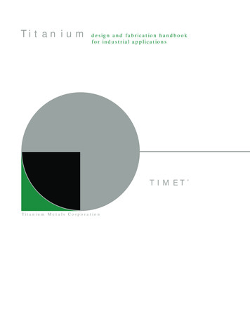
IntroductionZYGO corporation got contracted to build several EUV-L Micro-Field ExposureTools with 0.5NA, known as MET5.– Those tools are used for infrastructure development required for the EUVlithography industry to support printing at the 12nm node and below. Example: resist development. The lithography industry drive to print smaller feature sizes requires a shifttowards smaller wavelengths and higher NA and ultimately to tighteroptical surface specifications.Design Features:Modified Schwarzschild DesignM2 13.5nm wavelengthmirror 0.5NA 5X reduction Field dimension 30 x 200micronsReticle plane tilted by 6 degrees. Reticle (Mask) used in reflectionat EUV wavelengths 2016 Zygo Corporation.All rights reservedM1mirrorMask/ReticlewaferPerformance Requirements:Diffraction limited Imaging withTransmitted wavefront error: Center of the field 0.5nm RMS Edge of the field 1.0nm RMSAnd Flare 5%This is an upgrade to existing 0.3NA tools.Fitting the PO in existing platform volumeis a design and manufacturing challenge.3
Mirror Fabrication ZYGO Extreme Precision Optics (EPO) group in Richmond, California is a leaderin optical surfacing development.– 40 years of Computer Controlled Optical Surfacing (CCOS) use and development.– Over 15 years of Ion Beam Figuring (IBF) experience.– Over 20 years of EUV optics fabrication. During that period, EUV optics specs got tighter by a factor of 5– For all Ranges: Figure, MSFR, and HSFR CCOSIBF Technologies used infabrication of the EUVoptics for the MET5Projection Optic Box The M1 and M2 Mirrors are fabricated using a combination of conventionaland discrete computer controlled polishing techniques.– Aspheric departures of 46 and 51 microns.– Aspheric slopes of 8.6 microns/mm and 3.6 microns/mm 2016 Zygo Corporation.All rights reserved Extremely high for EUV optics4
Mirror Metrology Figure Metrology– Custom built, full aperture test station– Zygo Verifire MST– High precision computer generatedholograms (CGH’s)– Reproducibility of 20pm RMS Including mount deformations– Total Accuracy of both tests 0.2nm RMS Verified when first POB assembly wastested in our POB system test.M1 Mirror Test Station Full Spatial Range of metrology instruments– Figure test station– SASHIMI (custom built sub-apertureinterferometer)– Optical Profilometer 2.5x and 50x objectives– Atomic Force Microscope (AFM) 2016 Zygo Corporation.All rights reservedM2 Mirror Test Station5
Mirror Fabrication Results Average achieved RMS for 3 sets of mirrors (i.e. 3 complete systems)FigureM1 mirrorM2 mirrorRangesCA - 3mmMSFR3mm to 0.43mmResults0.050 nm RMS0.128 nm RMS0.088 nm RMSRangesCA - 8mm8mm to 1.2mm1mm - 10nmResults0.066 nm RMS0.123 nm RMS0.085 nm RMS– The MSFR and HSFR areevaluated by stitching thePSD curves from multiplemetrology instruments andintegrating under thecurve.HSFR1mm - 10nmEntire rangeCA - 10nm0.163 nm RMSCA - 10nm0.163 nm RMSThe PSD’s of various instruments are combined toget an integrated PSD for the entire surface Average Achieved Flare is:2.75% (spec is 5%)– System Flare is calculatedas total integrated scatter(TIS) from the MSFR rangesurface error. 2016 Zygo Corporation.All rights reservedMET5 M1 Mirror ID-1 PSD6
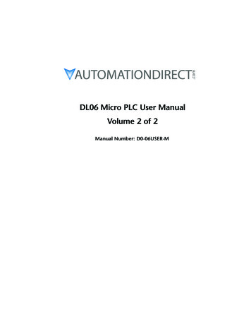
Opto-Mechanical Assembly and Alignment The POB structure is super Invar tomatch the low expansion material ofthe mirrors.M2mirrorBipodFlexures The bipod flexures rigidly constrain themirror positions, while allowing lowforce and moments, required toachieve low distortion of the opticalAdjustablesurface. The POB alignment is performed withthe hexapod legs and a softwarecontrol system.POBmountringHexapod LegsBipodFlexuresM1mirror Initial POB assembly is done with a Coordinate Measuring Machine (CMM) inorder to achieve initial alignment within the range of the hexapod legs.– Hexapod legs have super high accuracy (5nm) but limited range (100 microns)– CMM process yields wavefront errors 50nm RMS that can be corrected by usingless than 30 microns of hexapod leg adjustment. 2016 Zygo Corporation.All rights reserved7
Opto-Mechanical Assembly and Alignment The internally developed Hexapod Control software seamlessly convertswavefront data to mirror adjustments and finally to hexapod leg moves toadjust the wavefront.WavefrontError MapM1 MirroradjustmentHexapod legadjustmentPerform themove– The move executes in approximately 2 minutes with an M1 mirror positionaccuracy of 10nm laterally and 10nm axially. All 6 hexapod legs must move in a coordinated fashion even for thesimplest motion of the M1 mirror.POB initial alignment sequence showsthe WFE improving from 52nm RMSto approximately 1 nm RMS in onlyone adjustment cycle. Synthetic fringes shown, withwavefront map shown in lower rightframe 2016 Zygo Corporation.All rights reserved8
EUV Multilayer Coating The mirrors are coated at LawrenceLivermore National Laboratory (LLNL)with a graded EUV multilayer. The Mo/Si multilayers are optimized tomaximize reflectivity while minimizingresulting coating stress on the optic.EUV ML Coated M1 and M2 mirrors The Mo/Si coatings were measured atthe Advanced Light Source (ALS) atLawrence Berkeley National Laboratory(LBNL).Table of CoatingSpecificationsandAchievementsModeled reflectivity curves forindividual mirror and systemCoating MetricSpecAchievedSystem Transmission 25% 30%Centroid wavelength13.50nm /- 0.05nm 13.5BandwidthGoal 0.5nm0.59nm FWHM ALS MeasurementAdded Figure ErrorGoal 0.1nm RMS0.1nm RMS 2016 Zygo Corporation.All rights reservedMethod ALS Reflectivity measurementALS MeasurementSystem Wavefront Test9
Final Transmitted Wavefront performance The measured transmitted wavefront error of the 3 POBs is 0.25nm RMS.– This is less than half of the specification !!!Final Single Pass Transmitted Wavefront ErrorPOB 1POB 2POB 30.24nm RMS0.24nm RMS0.21nm RMS37 Term Zernike Fit of Transmitted Wavefront ErrorPOB 1POB 2POB 30.18nm RMS0.22nm RMS0.18nm RMS 2016 Zygo Corporation.All rights reservedThe Final ProjectionOptics system readyfor integration in avacuum system.10
POB System Wavefront Metrology and ReproducibilityThe POB system wavefront metrology isperformed with a Zygo Verifire MST, atvisible wavelength.Fold Mirror(common path)Transmission SphereM2MET5 POBM1Retro-Sphere 2016 Zygo Corporation.All rights reservedThe measured wavefront RMS hasreproducibility of better than 10picometers.Test IterationTest 1Test 2Test 3Test 4Test 5Test 6Test 7Test 8AverageRMS deviationP-V deviationWFE (nm .0020.00711
Final Transmitted Wavefront performanceAchieved Wavefront in greenSpecification in blackUnits: nm RMS Wavefront error over the field.– 0.15mm x 1.0mm field at thereticle (object side) 30 x 200 microns at wafer Largest Wavefront error over thefield is 0.48nm RMS for all 00.281.00.240.50.331.0 Less than half of the spec!!! Field aberrations include:astigmatism, field curvature andspherical aberration.– The Field aberrations areprescribed by the nominaloptical design 2016 Zygo Corporation.All rights reserved0.281.00.261.00.391.00.401.0Largest WFEover the field ofall 30.35POB’s1.00.481.012
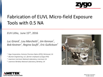
Final Transmitted Wavefront performance Due to the excellent wavefrontperformance achieved, the usable fielddimension that meets the specificationcan be increased.Reticle Field dimensionlimited by a 1nm RMSWavefronterror1– Allows the customer to use a larger areafor their printing tests.0.8 The increase in the useable areais 8x.– From(0.15mm x 1.0mm)– To 1.3mm2 (0.85mm x .40.60.81-0.4-0.6-0.8-1Field size from specification1nm limited field-1.2 2016 Zygo Corporation.All rights reserved13
SummaryThe fabrication of three 0.5NA EUV small field micro-exposure tools (MET) is complete.The results of all 3 systems are extremely good: The achieved single pass transmitted wavefront of 0.21 to 0.24nm RMS is less than halfof the 0.5nm specification at the center of the field. The maximum measured single pass transmitted wavefront across the specified field is0.48nm RMS, less than the 1.0nm specification.– This indicates that the dimension of the usable field may be larger than the 0.15mm x1.00mm specified field dimension by up to 8 times. The MSFR and HSFR are well in spec. The average achieved flare of 2.75% is close to half of the 5% specification The component test accuracy was confirmed by the POB system test measurement ofthe first assembly. The assembly process that was developed produces POBs that are close to finalalignment and the resulting POB assemblies have the conjugates near their targetpositions. The POB system test reproducibility is at the picometers level 2016 Zygo Corporation.All rights reserved14
mirror M2 mirror The POB structure is super Invar to match the low expansion material of the mirrors. The bipod flexures rigidly constrain the mirror positions, while allowing low force and moments, required to achieve low distortion of the optical surface. The POB alignment is p