Transcription
1994 by Alexander H. SlocumPrecision Machine DesignTopic 8Sensor systemsPurpose:Machine designers must be aware of the types of sensorsystems at their disposal. This lecture discusses selection ofsensors, and how they are used which can have a large impacton system performance.Outline: Sensors and Transducers Sensor performance characteristics Common analog output sensors Common optical sensors"Experience is the name everyone gives to their mistakes"Oscar Wilde8-1
1994 by Alexander H. SlocumSensors and Transducers A sensor is a device that responds to or detects a physicalquantity and transmits the resulting signal to a controller. A transducer is a sensor that converts (transduces) one formof energy to another form. Basic types of sensors: Absolute The output is always relative to a fixedreference, regardless of the initial conditions. Analog The output is continuous and proportional to thephysical quantity being measured. Digital The output can only change by an incrementalvalue given a change in the measured physical quantity. Incremental The output is a series of binary pulses. Each pulse represents a change in the physicalquantity by one resolution unit of the sensor. The pulses must be counted.8-2
1994 by Alexander H. SlocumSensor performance characteristics Accuracy All sensors are accurate in that an input causes anoutput. The trick is to figure out what the sensor is saying. Averaged output Random errors can be reduced by thesquare root of the number of averages taken. Frequency Response is the effect of the physical quantitybeing measured as it varies in time, on the output of thesensor. Hysteresis is the maximum difference in sensor outputbetween measurements made from 0-100% full scale output(FSO), and 100-0% FSO.8-3
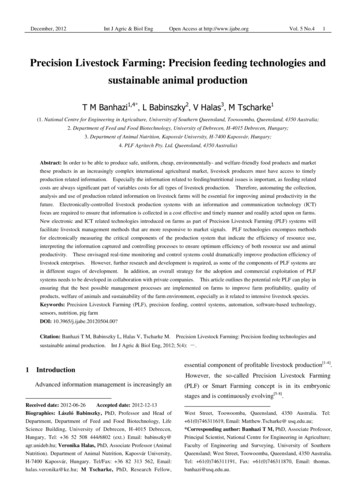
1994 by Alexander H. Slocum Linearity is the variation in the constant of proportionalitybetween the output signal and the measured physicalquantity. There are three different ways of fitting a straight line tothe sensor's output verses input graph: End point line. Best straight line. Least squares line.Best straight lineLeast squares LineOutputEndpoint LineMeasurand MeasurandMeasurand The end point line connects the endpoints of the sensor'sresponse curve. The best straight line is the line midway between the twoparallel lines that completely envelop the sensor'sresponse curve. The least squares line is the line drawn through thesensor's response curve such that the sum of the squaresof the deviations from the straight line is minimized.Mapping involves measuring the response of a sensor to aknown input under known conditions. The results are then expressed in tabular or analyticalform.8-4
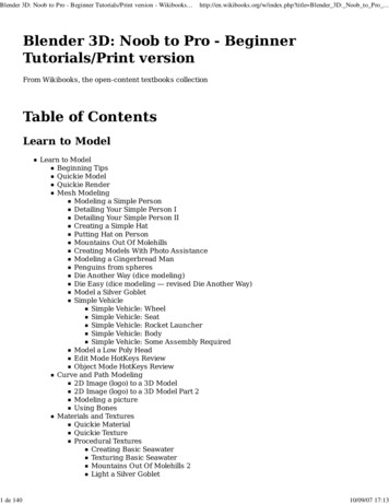
1994 by Alexander H. Slocum Most sensors' frequency responses are given in terms of the-3 db point. If a sensor detects motion of a part and the output from thesensor used to control an axis to correct for the error: The sensor should probably be operated well before its -3db frequency response point.The justification for this is:Decibels 915-3.0 The phase angle portion of the dynamic response: Error1 ppm10 ppm100 ppm1000 ppm1%10%30%Affects whether a sensor can be effectively used in acontrol system for a machine.If there is too much lag: It may not be possible for the mechanism to correct forerrors sensed . The error may have already irreversibly affected theprocess.8-5
1994 by Alexander H. SlocumCommon analog output sensors Capacitance sensors Hall effect sensors Inductive digital on/off proximity sensors Inductive distance measuring sensors Inductosyns Linear & rotary variable differential transformers Magnetic scales Magnetostrictive sensors Potentiometers Velocity sensors8-6
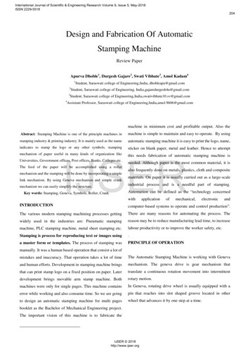
1994 by Alexander H. SlocumCapacitance sensors General constructionGrounded bodyGuardProbeSensorTarget GapEnd viewTargetField propertiesGuardBodySensor Generally regarded as the most accurate type of analoglimited range of motion sensor.8-7
1994 by Alexander H. Slocum Typical applications: Position sensor for micropositioners. Material thickness sensing:DielectricMaterialMetalProbeProbeMetal Metrology equipment (e.g. spindle error analyzers):Orbit tracing andshaft error motionsDiameterSheet thicknessConcentricityTwo-axisalignmentStatic and dynamicdisplacements8-8
1994 by Alexander H. SlocumInductive digital on/off proximity sensors General operating principle (Courtesy of Turck Inc.):Metal ectorActivated(Oscillatordamped)OutputCoil and coreOutput Typical applications: Industrial limit switches. "Coarse" home position sensor for machine tools (finehome position via encoder home pulse).8-9
1994 by Alexander H. SlocumInductosyns General operating principle:ScaleScaleSliderSliderTwo windings 90 out of phase Rotary Inductosyns operate on a similar principle. Inductosyns were used on machine tools before robustencoders and magnetic scales were developed. Typical applications: Rotary tables. linear motion machine tool axes.8-10
1994 by Alexander H. SlocumLinear and rotary variable differential transformers General operating principle(Courtesy of Lucas Schaevitz):VoutFerro-magnetic CoreX motionLinear operatingregionV reference Typical applications: Metrology equipment. Small range of motion servo controlled devices.8-11
1994 by Alexander H. SlocumMagnetic scales Operates on same principle that allows a disk drive to locatestored information. More robust then linear optical encoders. Magnetically encoded linear scale and sliding read head(Courtesy of Sony Magnescale Inc.): Becoming more and more common sensor for measuringlinear motion of machine tool axes.8-12
1994 by Alexander H. SlocumMagnetostrictive sensors General operating principle for position sensingSystems Corp.):Waveguide twistExternalmagnetic field(Courtesy of MTSStrain tapeMagnet1 of 4 magnetsinstalled 90 apartInteraction ofmagnetic fieldscauses waveguideto twistWaveguideSensing coilMagnetic field frominterrogating pulseConductingelement Externalmagnet assemblyTypical applications: Moderate accuracy linear position sensing. Position sensing of hydraulic pistons (sensor can beplaced inside the cylinder).8-13
1994 by Alexander H. SlocumPotentiometers General operating principle (Courtesy of Vernitech Corp.):Molded plastic wiper blockwith dovetail guideSpring loaded hemisphericalrod-to-wiper couplingExtrudedAluminumhousingFlexibleshaft sealConductive plastic filmStainless steel rodPrecious metalalloy wipers Typical applications: As a sensor in a high reliability all analog servo system. Short range of motion servo systems.8-14
1994 by Alexander H. SlocumVelocity sensors Linear velocity sensors tend to act like antennas, so theypick up EMI easily; thus their use should be avoided. Rotary velocity sensors (tachometers) are essentially drivenDC motors. Typical applications: Speed control. Analog velocity feedback.8-15
1994 by Alexander H. SlocumCommon optical sensors Autocollimators Optical encoders Fiber optic sensors Interferometric sensors Laser triangulation sensors Vision systems8-16
1994 by Alexander H. SlocumAutocollimators Used to measure the change in angle of a target mirror. General construction (Courtesy of Rank Taylor Hobson):Light sourceCondenserθMonochromatic filterTarget reticleOptical micrometerrefractor blockEyepieceEyepiecereticleBeamsplitterPhotocell ReferenceMirrorMeter oranalog to digital interfaceThe measured angle is independant of the distance of thetarget.8-17
1994 by Alexander H. SlocumTypical applications: Small angle servo systems. Straightness measurement (after Moore):AutocollimatorCorrectTargetIncorrect target steppingPosition(inches)61218243036Readingseconds of arc0.0-0.4-0.2-0.8-1.5-1.306Accumulatedseconds of arc0.0-0.4-0.6-1.4-2.9-4.21218Correctionseconds of arc 0.7 1.4 2.1 2.8 3.5 4.22430Actual errorseconds of arc 0.7 1.0 1.5 1.4 0.60.036 inches0Shaded section to be lapped-58-18Seconds of arc
1994 by Alexander H. SlocumAs with many optical systems, changes in the indexof refraction affect sensor output Edlen's equation:293 K(n-1) x 107 (nnominal - 1) x 107 x Pressure x760 mm T( K) Effect of an index of refraction gradient (e.g., caused by atemperature gradient) on the propagation of a plane of light:dyn n y dyYnX For small gradients dT/dy in airdθ K dTdx nT2 dy8-19
1994 by Alexander H. SlocumOptical encoders Common types: Incremental position encoders. Interpolation (E.G., Moire fringe) encoders. Absolute position encoders. Diffraction encoders. Quadrature logic. Typical characteristics of optical encoders.8-20
1994 by Alexander H. SlocumIncremental position encodersLight sourceHome positionmarkCollimating lensIncrementally encoded diskIndex plateFocusing lensEncoder shaftPhotodiodeIncrementallyencoded disk Most commonly used type. Reasonable resolution. Inexpensive and widely available. Quality is typically proportional to price. Poor gratings and poor electronics lead to outputsignal orthogonality errors. Quadrature signals are 90o N o , which causevelocity calculation errors in control loops.8-21
1994 by Alexander H. SlocumInterpolation encoders Output is a sine wave and a cosine wave: Can be used to interpolate (typically 25x) beyond theresolution provided by the slits. The resulting signal can still be used with quadrature logicto gain a 4x increase in resolution. Example, Moire fringes:Grid AGrid B8-22Grid B on top of Grid A
1994 by Alexander H. SlocumAbsolute position encodersLight sourceGray scale disclight detectorsEncoder shaftInterface electronicsAbsolute position output (e.g., 10 bits) Not commonly used on machine tools because most haveto be reset upon startup anyway. Moderate resolution for a price.8-23
1994 by Alexander H. SlocumDiffraction encoders With conventional encoders, slit width and henceresolution is limited by diffraction. Diffraction encoders use diffracted light to createinterference patterns. These are used to generate very high resolution sineand cosine waveforms for interpolation. Sine and cosine waveforms are assumed to be of equalamplitude. This is a spurce of error that limits accuracy.Typical construction (Courtesy of Canon USA Inc.):DiodesPolarizing platePolarizing PrismPolarizing plateBeam SplitterLaser DiodeCollimator lensQuarter wave plateMirrorMirrorQuarter wave plate1st orderdiffractedlightGrating disk1st orderdiffractedlightReflectorReflector8-24
1994 by Alexander H. SlocumFiber optic sensors Condition for low loss propagation of light through a fiber(Courtesy of 3M):n2θAcceptance coneCritical angle n1Construction of a fiber optic cable and typical defectsof 3M):(CourtesyKevlar braidDensity changemicrobendTight tubeIrregular end finishBufferCladdingOptical fiberPVC jacketBubbleImpurity8-25
1994 by Alexander H. Slocum Generalized performance characteristics for three types ofreflective fiber optic probes (Courtesy of 3M):Reflected Light Intensity1.00.8HemisphericalBack slope0.6RandomHemispherical0.4PCS pair0.2Front slope1.0PCS pairRandom3.02.0Distance (mm)4.05.0(Courtesy of 3M) Bifurcate probe used in a reflective scanning mode3M):Light source connectedto this cableDetector connected tothis cable Transmission leg(Courtesy ofTargetReceiving legTypical applications of fiber optics in precision machines: To carry light to or from a sensor (e.g. interferometer). To carry light to and from a surface for measuring theposition of the surface.8-26
1994 by Alexander H. SlocumOptical Heterodyne Interferometers Michelson interferometers count fringes which limits theresolution to about l/8. Heterodyne techniques can be used to achieve two orders ofmagnitude greater resolution:Reference and measurement tretroreflectorReceiverMeasurement andcomputationelectronics DisplaymachinetoolcontrollerConstruction of a laser head used with an Optical HeterodyneInterferometer (Courtesy of Zygo Corp.):Beam efringentcombiningprismFrequency shiftedorthogonally polarizedmeasurement andreference beamsApertureAperatureDetectorsThermal controllerHe:Ne LaserAcousto-opticfrequency shifterHeaterPolarizer8-27
1994 by Alexander H. Slocum One of many processes for determining optical path changeusing phase measurement (Courtesy of Zygo Corp.):Reference channel:Acousto-opticfrequency shifter2mlevelsMeasurement channel:Receiver8-28
1994 by Alexander H. SlocumBeam handling components Beambender: A plane mittor:25 mm cube Careful to make the bend 90o to avoid polarizationleakage problemsLinear retroreflectors: Return light parallel to its incomingpath:25 mm38 mm D28.5 mm D38 mm24 mm long Beamsplitter: Separates orthogonally polarized beams intotwo components:38 mm cube25 mm cube8-29
1994 by Alexander H. Slocum Linear displacement interferometer:beamsplitter and a retroreflector:38 mmRetroreflectorMeasurement andreference beams38 mmMeasurement beam38 mmPolarizationbeamsplitter Combines polarizationRetroreflectorPlane mirror interferometer (Courtesy of Zygo Corp.):38mm32 mm square2.5 mm 1/4 waveplates12.7 mmbeam spacingRetroreflector8-30
1994 by Alexander H. Slocum Differential plane mirror interferometer for linear orangular motion measurements (Courtesy of Zygo Corp.):Polarization beamsplitterHalf wave platePolarizationshear plate38 mm94 mmQuarterwave plate38 mmTargetmirrorRetroreflectorReference mirrorMeasurement beamReference Beam For linear measurements, the reference mirror lets beamspass through diagonally opposite holes. For angular measurements: The reference mirror lets beams pass through holesaligned on an axis parallel to the axis of rotation.8-31
1994 by Alexander H. SlocumStraightness interferometer and reflector(C
Precision Machine Design Topic 8 Sensor systems Purpose: Machine designers must be aware of the types of sensor systems at their disposal. This lecture discusses selection of sensors, and how they are used which can have a large impact on system performance. Outline: Sensors and Transducers Sensor performance characteristics