Transcription
Technical InformationStraumann Bone Level Prosthetic ProceduresBasic Information
Contents1. Straumann Bone Level Implant – Straumann expertise applied at bone level 32. General information 42.1 CrossFit Connection 42.2 Prosthetic options 62.3 Abutment Overview 2.4 Coding 3. Preoperative planning 810123.1 Wax-up/Set-up 123.2 X-ray template with reference spheres 123.3 Custom-made drill template 134. Soft tissue management 144.1 Soft tissue management solutions 144.2 Prefabricated healing abutment 154.3 Overview consistent emergence profiles 184.4 Customizable Healing Abutment 214.5 Temporary Abutment regular CrossFit (RC) – Polymer with titanium-alloy inlay 234.6 Temporary abutment – Titanium alloy (TAN) 305. Impression taking 335.1 Options for impression taking 335.2 Open-tray impression 345.3 Closed-tray impression 385.4 B ite registration 426. Restoration 446.1 CrossFit Plan SET/Plan abutment 446.2 Anatomic (and meso) Abutment 476.3 Gold Abutment for crown 546.4 Gold abutment for bridge 666.5 Cementable abutment 776.6 Straumann Screw-retained Abutments 926.7 Abutment for bars 1166.8 LOCATOR Abutment 1267. Aids and instruments 1427.1 SCS Screwdriver 1427.2 Polishing Aid 1427.3 Ratchet and Torque Control Device 1437.4 Assembling the Ratchet and the Torque Control Device 1457.5 Tightening an abutment to 35 Ncm 1478. About sterilization 1499. Important guidelines 150
Purpose of this guideThis guide describes the essential steps required for the fabrication and insertion ofprosthetic restorations for Straumann Bone Level Implants.For detailed information regarding implantation and soft tissue management, pleaserefer to the Basic information on the surgical procedures – Straumann Dental ImplantSystem, 152.754, or the DVD Surgical and prosthetic procedures with the Straumann Bone Level Implant, 150.760.Note: Procedures that apply for technicians in the dental lab are marked green.Procedures that apply for prosthodontists are marked grey: Lab procedureProsthetic procedureNot all products shown are available in all markets.All products shown in this guide are for single use only if not indicated otherwise.
1. Straumann Bone Level Implant – Straumannexpertise applied at bone levelThe Straumann Bone Level Implant provides you with a solution for all bone level treatments – Straumann expertise and quality built in.Its design is based on the latest technology and scientific know-how in implant dentistry. Moreover, it respects key biological principles,brings predictable esthetic results.Consistent Emergence Profiles Experience simplified soft tissue management fromstart to finishCrossFit connectionFeel the fit of the self-guiding connectionBone Control Design Optimize crestal bone preservationby adhering to biological principlesBone Control Design Consistent Emergence Profiles CrossFit connectionThe unique Bone Control Design isThe prosthetic components of theThe prosthetic connection is intuitive,based on key biological principles andStraumann Bone Level Implant line areself-guiding and easy to grasp. Thethorough scientific research to supportdesigned to facilitate highly estheticCrossFit connectioncrestal bone preservation and stable softrestorations that perfectly mimic natural Provides a clear-cut insertion throughtissue margins. It features the followingteeth. These implant line components,the guidance by 4 grooves and thestrengths:designed to match the abutment profiles,deep, conical connection. Fast osseointegration with theallow you to easily attain esthetic resultsSLActive surface technology Optimal transmission of forces intothe bone through the biomechanicalimplant design Consideration of the biologicalthrough soft tissue management. Ensures precision against rotationthrough orthogonal fit betweenimplant and abutment. Gives prosthetic flexibility withmechanical long-term stabilitythrough its conical connection.distance with a horizontal distance ofmicro gap to bone Reduction of micro movements whilecontrolling the micro gap through aconical connection3
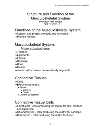
2. General information2.1 CrossFit ConnectionThe Straumann Bone Level Implant features an intuitive implantabutment connection that is self-guiding and enables simplepositioning. It allows clear-cut insertion with all components andprovides outstanding protection against rotation as well as longterm stability.Precision and simplicity: 4 groovesThe CrossFit connection features 4 grooves for the repositioning ofprosthetic components.This configuration is characterized by: Simple implant alignment Clear-cut and guided component insertion Flexibility in the placement of angled prosthetic components Optimal protection against rotation ensured byorthogonal implant-abutment fitInternal connection viewedfrom above, showing the4 internal grooves.Abutment insertion, step 1. The abutment is placed on the 4 grooves in the implant.4
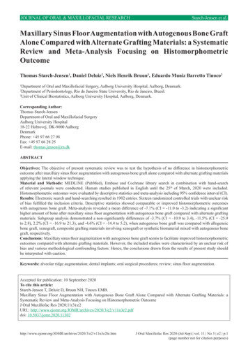
Abutment insertion, step 2.The abutment is turned in until it isaligned with the 4 implant grooves.Abutment insertion, step 3.The abutment then falls into the final position.Abutment in place, showing the precise orthogonal fitbetween implant and abutment.Reliability and flexibility: Conical connectionThe CrossFit connection features a cone with improved mechanical properties,providing more flexibility for prosthetic treatments.The conical prosthetic connection provides: Reduced micro movements and minimized microgap Outstanding mechanical long-term stability and optimized stress distribution Exact implant-abutment fit Simplified impression taking even with divergently positioned implants5
2.2 Prosthetic optionsGold Abutment, for crownScrew‑retainedStraumann CARES Ceramic AbutmentStraumann Variobase AbutmentStraumann Screw-retainedAbutmentSingle crownAnatomic AbutmentMeso AbutmentGold Abutment, for crownCement‑retainedStraumann CARES Ceramic AbutmentStraumann Variobase AbutmentStraumann CARES Titanium AbutmentCementable AbutmentGold Abutment, for bridgeScrew-retainedStraumann Screw-retainedAbutmentAnatomic AbutmentBridgeMeso AbutmentGold Abutment, for crownCement-retainedStraumann CARES Ceramic AbutmentStraumann CARES Titanium AbutmentStraumann Variobase AbutmentCementable Abutment6
Retentive AnchorLOCATOR AbutmentAbutment for Bars, GoldBarRemovable over-denturesAbutment for Bars, TitaniumStraumann Screw-retainedAbutmentCustomized barGold Abutment, for bridgeAnatomic AbutmentTelescopeMeso AbutmentGold Abutment, for crown7
2.3 Abutment OverviewAnatomic AbutmentMeso AbutmentSingle crownScrew-retainedCement-retained Gold Abutment, forcrown BridgeScrew-retainedCement-retainedRemovable overdenturesTelescopeGold Abutment, forbridge Retentive anchor Straumann CARES CeramicAbutmentStraumann CARES Titanium Abutment BarImpressionImplant level TitaniumTitaniumCeramicor Ceramicor ZirconiumdioxideTitanium6.26.26.36.41)1)Abutment levelMaterial*Chapter*See information on sterilization conditions in chapter 8.8
Straumann Variobase Abutment CementableAbutment Straumann Screwretained AbutmentAbutment forBars, GoldAbutment forBars, TitaniumLOCATOR Abutment Titanium alloyTitaniumTitanium alloyCeramicor TitaniumTitanium alloy2)6.76.86.96.96.10 1) For further information regarding CARES implant-borne prosthetics,please see the Basic information on the Straumann CARES implant-borneprosthetic procedures, 152.822/en.2) For further information regarding Variobase , please refer to thebrochure Basic information on Straumann Variobase , 490.062/en.9
2.4 CodingThe Straumann Bone Level Implant line has a simple and consistent color codingand laser markings for quick and precise identification of secondary parts, surgicalinstruments and auxiliaries. This concept simplifies the communication substantiallybetween the individuals involved in the treatment process.The following scheme illustrates the above mentioned color codings and laser markings:ConnectionImplant Narrow CrossFit (NC)3.3 mmRegular CrossFit (RC)4.1 mm4.8 mmLaser marked (NC/RC)Color-coded10InstrumentsImplant Closure screw
Healing abutmentImpression postImplant analogTemporary abutment,AbutmentVITA CAD-Temp Screw headScrew head11
3. Preoperative planningComprehensive pre-implantation diagnosis, evaluation and planningare prerequisites to ensure treatment success. The implant forms theapical extension of the restoration and is thus the planning basis forthe surgical procedure aiming at a specific prosthetic result.3.1 Wax-up/Set-upTo determine the topographical situation, axial orientation and theappropriate implants, making a wax-up/set up using the previouslyprepared study cast is recommended. Subsequently, the type ofsuperstructure can be defined.The wax-up/set-up can later be used as the basis for a custom-madeX-ray or drill template and for a temporary restoration.Abutments should always be loaded axially. Ideally, the long axis ofthe implant is aligned with the cusps of the opposing tooth. Extremecusp formation should be avoided as this can lead to unphysiologicalloading.3.2 X-ray template with reference spheresFor easier determination of bone availability, the use of an X-raytemplate with X-ray reference spheres is recommended. First, markthe selected implant positions on the study cast. Then fix the X-rayreference spheres at the marked points and make the vacuum-formedtemplate with the spheres. The subsequently taken X-ray or computertomography (CT) gives information on bone availability, quality andmucosal thickness. Based on these properties the number of implants,the exact implant positions, diameters and lengths can be determined.12The X-ray reference sphere has a diameter of 5 mm. Theimage of the sphere on the X-ray provides the referencevalue for the magnification scale.
3.3 Custom-made drill templateA custom-made drill template can facilitate planning and the preparation of theimplant bed and enables precise use of the cutting instruments. The basis of planningwhen making this surgical template should be the desired prosthetic result.With these components, a surgical drill template can be produced in the usual manner:Art. No.ArticleDimensions049.810V4Drill sleeve with collarheight 10 mmoutside 3.5 mminside 2.3 mm049.818V4Stepped pin for 049.810height 16 mm 2.2/3.5 mm049.816V4Pin for 049.810height 16 mm, 2.2 mm049.817V4Pin for 049.810height 10 mm, 2.2 mm049.819V4Pin for 049.810height 16 mm, 3.5 mmVacuum-formed template with integrated drillsleeve as drilling template.13
4. Soft tissue managementThe Straumann Bone Level Implant line puts a strong emphasis on estheticconsiderations. It offers tailor-made solutions that allow for natural soft tissue shapingand maintenance in all indications. A versatile portfolio of healing and temporaryabutments is available, including customizable products made of polymer for easy andfast processing.Healing abutmentTemporary restorationFinal restorationEsthetic results are determined by successful soft tissue management. To optimizethe soft tissue management process, various components with Consistent EmergenceProfiles are available in the prosthetic portfolio of the Straumann Bone Level Implant.This applies for all healing abutments, the temporary abutment and the abutmentsfor the final restoration. Thus, the emergence profiles are uniform throughout thetreatment process (for optimal healing abutment selection see chapter 4.3).4.1 Soft tissue management solutionsHealing AbutmentPrefabricated healing abutment(titanium)chapter 4.214Temporary AbutmentCustomizable healingabutment (polymer)chapter 4.4(titanium alloy (TAN))chapter 4.6(PMMA with titaniumalloy inlay)chapter 4.5
4.2 Prefabricated healing abutmentIntended use Soft tissue management Closure of implant connection for submerged and non-submergedhealingCharacteristicsSimple One-piece design Color-coded and laser-marked Anatomically shaped emergence profiles, matching impression postand final abutments (for optimal healing abutment selection seechapter 4.3)Reliable CrossFit connection Prosthetic procedure: pages 16–1715
4.2.1 Prefabricated Healing Abutment – Prosthetic procedureStep 1 – Insertion1 Insert the healing abutment with the SCS screwdriver. The friction fitsecures the healing abutment to the instrument during insertion andensures safe handling. Hand-tighten the healing abutment. The cone-in-cone designprovides a tight connection between the two components.Step 2 – Wound closure Adapt the soft tissue and suture it back tightly around the abutment.162
Prosthetic procedureOptional: Bottle-shaped and Customizable Healing AbutmentThe bottle-shaped healing abutment pre-shapes the soft tissueby allowing for a slight excess of mucosa during healing. Theinsertion of the final restoration pushes the formed tissueoutward, supports the creation of a naturally shaped periimplant soft tissue.The customizable healing abutment allows for individual softtissue management.Note: Do not use the customizable healing abutment for longerthan 6 months. Healing abutments are delivered non-sterile andcan be sterilized prior to use (for instructions see chapter 8).17
4.3 Overview consistent emergence profiles Which healing abutments suit which abutments?Cement-retained solutionsPlatformNCAnatomic AbutmentTypeCementable AbutmentMaterialTiTiTiTiAngle0 15 0 0 (mm)4.04.03.55.0GH (mm)2.03.5GH (mm)3.55.0 .03.03.55.04.8TypeConical healing AbutmentPlatformRCAnatomic AbutmentTypeMaterialTiCementable AbutmentTiTiTiAngle0 15 0 0 (mm)6.56.55.06.5GH (mm)2.03.5GH (mm)4.06.0 .06.05.0TypeConical Healing Abutment186.5
Screw-retained solutionsPlatformNCScrew-retained AbutmentTypeMaterialTANTANTANTANAngle0 0 17 30 (mm)3.54.64.6GH (mm)1.0GH (mm)2.0 .54.05.53.54.84.8TypeConical Healing AbutmentPlatformRCScrew-retained AbutmentTypeMaterialTANTANTANAngle0 17 30 (mm)4.64.64.6GH (mm)1.02.54.0GH (mm)2.04.06.0 (mm)2.54.05.52.54.05.54.05.05.0TypeConical Healing Abutment19
Hybrid solutionsPlatformNCScrew-retained AbutmentTypeMaterialLOCATOR TANTANTANTANAngle0 0 17 30 0 (mm)3.54.64.64.63.8GH (mm)1.0GH (mm)2.0 .0Ti nical Healing AbutmentPlatformRCScrew-retained AbutmentTypeMaterialAngle (mm)TANTANTANTi alloy0 17 30 0 4.64.6GH (mm)1.02.54.0GH (mm)2.04.04.0 (mm)LOCATOR 5.02.54.04.65.52.54.03.85.53.55.0TypeConical Healing Abutment201.02.02.03.04.04.05.05.06.06.0
4.4 Customizable Healing AbutmentIntended use Individual soft tissue management for esthetic cases Closure of implant connection during healing phaseCharacteristicsSimple Polymer material allows for easy and quick chair-side modification Easy-to-achieve esthetics due to gingiva-colored and modifiablepolymer material Reliable CrossFit connectionNote: Do not use for longer than 6 months.The customizable healing abutment can be shortened vertically nomore than 5 mm. Prosthetic procedure: page 2221
Prosthetic procedure4.4.1 Customizable Healing Abutment – Prosthetic procedureStep 1 – Customizing1a Individualize the healing abutment on an analog according tothe mouth situation. Heatless wheels and new cross-toothedmillers are recommended for grinding. To avoid smearing of the polymer, adjust the bur speedproperly (low rpm frequency, little pressure).Step 2 – Insertion Hand-tighten the healing abutment in the implant with theSCS screwdriver and temporarily seal the screw channel (e.g.with composite).221b
4.5 Temporary Abutment regular CrossFit (RC) – Polymer with titanium-alloy inlayIntended use Individual soft tissue management for esthetic cases Screw- or cement-retained temporary crowns Cement-retained temporary bridgesCharacteristicsSimple Polymer material allows for easy and quick chair-side modification Easy-to-achieve esthetics due to tooth-colored and modifiablepolymer materialReliable Precise fit and high stability due to reinforcement with titanium-alloyinlayCrossFit connectionNoteDo not use for longer than 6 months. Place temporary restoration outof occlusion. The devices are provided non-sterile and are for single use only. The abutment must be secured against aspiration. The abutmentscan be processed with cleaning/disinfecting agents such as Ethanol,Tego Cid 2 %, Micro 10 4 %, Cidex OPA pure and Grotanat 2 %. The abutment can be steam-sterilized (121 C / 250 F for 20 minutes).23
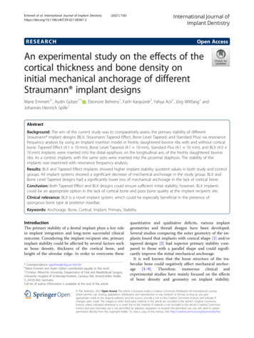
4.5.1 Prosthetic procedure for Temporary Abutment RCModification of abutments – How far to reduce the dimensionsNNCNCRNWNRC1 mm maxreduction1 mm maxreductionArea of possible reductionArea of possiblereductionArea of possiblereductionRed line indicates the area of maximum reductionNote: Please refer to the graphics above for details on modificationlimits.The temporary abutment height can be shortened with standard toolsand techniques, but should not be reduced beyond the metal core. Thewidth must not be reduced by more than 1 mm at the thickest part(NNC, NC) or further than the metal margin (RN, WN, RC).Option A: Screw-retained temporary crownStep 1 – Individualization – Removing materialIndividualize the temporary abutment on an analog according to themouth situation. Fine-cut tungsten-carbide tools are recommended forprocessing this polymer material.Insertion in master modelHand-tighten the temporary abutment in the implant/implant analogwith the SCS screwdriver and temporarily seal the screw channel (e.g.with cotton).24
Step 2 – Option A: Fabricating the temporaryrestoration – Direct veneeringDirectly add the veneering material in order to fabricate thetemporary restoration.Step 2 – Option B: Fabricating the temporaryrestoration – Vacuum stentsCreate the temporary restoration according to standard techniques (e.g. vacuum stents).Note: Before adding up any material or performing correctionswith veneering material (i.e. VITA VM LC materials, refer tothe manufacturer’s instructions), the surface of the temporaryrestorations must be cleaned and wetted with modeling liquid.Note: Clean the abutment with a steam jet.25
Step 3 – FinishingRemove excess acrylic, reopen the screw channel and finish thetemporary restoration.Note: Restorations made from VITA CAD-Temp can be pre-po-lishedwith a suitable silicone polisher and a small goat-hair brush. Standardacrylic polishing agents that are also suitable for intraoral use are usedfor high luster polishing.Avoid creating excessive heat.Important:Careful polishing is absolutely necessary to achieve a perfectresult and to avoid plaque accumulation and related negativeeffects on the shade.Use a polishing aid or implant analog to protect the implantconfiguration while polishing the temporary restoration.Step 4 – Final insertionClean and sterilize the polished temporary restoration(refer to the manufacturer’s instructions of the veneeringmaterial).Place the temporary restoration on the implant and tightenthe screw between 15 Ncm and 35 Ncm (depending on implantstability) using the SCS screwdriver along with the ratchet andthe torque control device.26
Option B: Cement-retained temporary crownStep 1 – Individualization – Removing materialIndividualize the temporary abutment on an analog according to themouth situation. Fine-cut tungsten-carbide tools are recommendedfor processing this polymer material.Step 2 – Fabricating the cement-retained temporary single crownUse a standard procedure to fabricate the cement-retained singlecrown (e.g. grind out a prefabricated plastic tooth).27
Step 3 – Final insertionClean and sterilize the polished temporary abutment.Place the customized temporary abutment on the implant and tightenthe screw between 15 Ncm and 35 Ncm (depending on implant stability)using the SCS screwdriver along with the ratchet and the torque controldevice.28
Lab procedureProsthetic procedureCover the screw head with absorbent cotton or gutta-percha and sealthe screw channel temporarily (e.g. with absorbent cotton).Step 4 – Cementing the temporary single crownCoat the internal configuration of the crown with temporary cementand cement it on the temporary abutment.29
4.6 Temporary abutment – Titanium alloy (TAN)Intended use Engaging abutments are used for– Screw- or cement-retained temporary crowns– Cement-retained temporary bridges Non-engaging abutments are used for– Screw-retained temporary bridgesCharacteristicsMore solutions Narrow diameter for narrow interdental spaces Crowns and bridges Screw- and cement-retained Anterior and posterior regionReliable Precise fit and high stability due to titanium alloy (TAN) material CrossFit connection for engaging abutmentsNote: Do not use for longer than 180 days.Place temporary restorations out of occlusion.The temporary abutment can be shortened vertically no more than6 mm with standard tools and procedures.The devices are provided non-sterile and are for single use only.The abutment must be secured against aspiration.Refer to the veneer material manufacturer for information regardingthe disinfectants that can be used.The abutments can be processed with cleaning/disinfecting agentssuch as Ethanol, Tego Cid 2 %, Micro 10 4 %, Cidex OPA pure andGrotanat 2 %.The abutment can be steam-sterilized (134 C/ 273 F for 5 min). 30Lab procedure: pages 31–32Prosthetic procedure: pages 31–32
Lab procedureProsthetic procedure4.6.1 Temporary Abutment – Procedure for a screw-retained bridge temporary restorationStep 1 – Preparation1a Mount the temporary abutment on the master cast or in patient’smouth. Mark the appropriate heights according to the individual situation. Remove the abutment from the patient’s mouth. Shorten the abutment as necessary using standard technique.1b The upper section of the abutment should be sandblasted beforeopaquing. Coat the temporary abutment with opaquer to prevent thetitanium alloy (TAN) from showing through. Screw the copings onto the implant in the patient’s mouth and1ctemporarily seal the screw channels (e.g. with cotton).Note: Repeat the procedure for screw- or cement-retained crownprovisional restoration by using the engaging temporary abutments.Use the SCS screwdriver 046.401 (short) or 046.402 (long). Dependingon implant stability, tighten with a torque between 15 Ncm and 35Ncm. Hand-tighten on the master cast. The abutment should notdiverge more than 30 for a screw-retained bridge. Manufacture ameso structure with a cemented restoration in order to compensatedivergences greater than 30 .31
Lab procedureProsthetic procedureStep 2 – Creating the provisional2a Use standard procedure to fabricate the provisional (e.g.prefabricated crown or bridge form or vacuum-formed sheettechnique as shown here). The retention elements ensure propermechanical bonding of the veneering material to the temporaryabutment. Remove excess acrylic, reopen the screw channel and finish thetemporary restoration.2bStep 3 – Inserting the provisional Clean and disinfect the polished temporary restoration, place it onthe implants and tighten the screw between 15 Ncm and 35 Ncm(depending on implant stability) using the SCS screwdriver alongwith the ratchet and the torque control device (for instructions seechapter 7.5). Cover the screw head with absorbent cotton or gutta-percha andseal the screw channel with temporary veneering material (e.g.composite).323
5. Impression taking5.1 Options for impression takingImpressions for the Straumann Bone Level Implant can be taken by either of the twofollowing procedures:Open-tray procedureClosed-tray procedurechapter 5.2chapter 5.3Straumann Bone Level ImplantThe procedure used depends on the user’s preference and the clinical situation. Bothprocedures are described in the following chapters.33
5.2 Open-tray impressionIntended use Open-tray impression procedureCharacteristicsSimple Color-coded components corresponding to prosthetic connection Slender emergence profile accommodates space limitations Guide screw can be tightened either by hand or with the SCSscrewdriverReliable High-precision impression components give an exact replica of theintraoral situation Clear-cut tactile response from the prosthetic connection verifiesproper seating of componentsNote: Open-tray impression procedure requires a custom-made traywith perforations.Impression posts are intended for single use only to ensure optimal fitand precise impression taking for each patient. 34Prosthetic procedure: pages 35–36Lab procedure: page 37
Prosthetic procedure5.2.1 Open-tray impression – Prosthetic procedureStep 1 – Positioning the impression post1 Ensure sufficient access to the implant site in order to avoid pinchingin the gingival tissue. Be aware that the sulcus may collapse rapidlyonce the healing components have been removed. Clean the internal configuration of the implant thoroughly fromblood, tissue, etc. prior to the impression procedure. Place the impression post accurately into the implant and handtighten the guide screw. In case of occlusal space limitation, the length of the impressionpost can be reduced by one retention ring after the guide screw hasbeen removed.35
Prosthetic procedureStep 2 – Impression taking2a Make perforations in the custom-made impression tray (light curedresin) according to the individual situation so that the positioningscrew of the impression post sticks out. Take the impression using an elastomeric impression material2b(polyvinyl siloxane or polyether rubber).Note: Due to its low tensile strength, hydrocolloid is not suitable forthis application. Uncover the screws before the material is cured.2c Once the material is cured, loosen the guide screws and removethe tray.2d36
Lab procedure5.2.2 Open-tray impression – Lab procedureStep 1 – Analog repositioning and fixing1a Reposition and fix the analog in the impression using the guidescrew. To avoid inaccuracies when connecting, the analog must bepositioned exactly in line with the grooves of the impression postbefore screwing in.1bNote: When tightening the screw, grasp the retentive section of the1canalog securely to prevent the impression post from rotating. This isespecially important with a shortened post.Step 2 – Fabricating the master cast2 Fabricate the master cast using standard procedure and type-4dental stone (DIN 6873). A gingival mask should always be usedto ensure that the emergence profile of the crown is optimallycontoured.37
5.3 Closed-tray impressionIntended use Closed-tray impression procedureCharacteristicsSimple Color-coded components corresponding to prosthetic connection Slender emergence profile to accommodate space limitations No additional preparation (i.e. perforation) of tray requiredReliable High-precision impression components give an exact replica of theintraoral situation Clear-cut tactile response from the prosthetic connection verifiesproper seating of componentsNote: Impression posts are intended for single use only to ensureoptimal fit and precise impression taking for each patient.A spare cap is provided with each package in case there is a need toretake the impression immediately. 38Prosthetic procedure: pages 39–40 and 42–43Lab procedure: page 41
Prosthetic procedure5.3.1 Closed-tray impression – Prosthetic procedureStep 1 – Positioning the impression post1a Ensure sufficient access to the implant site in order to avoid pinchingin the gingival tissue. Be aware that the sulcus may collapse rapidlyonce the healing components have been removed. Clean the internal configuration of the implant thoroughly fromblood, tissue, etc. prior to the impression procedure. Place the impression post accurately into the implant and tightenthe guide screw hand-tight (using the SCS screwdriver).Note: Ensure that the lateral planar areas of the post are facing mesialand distal. Place the polymer impression cap on top of the fixed impression1bpost. Ensure that the color of the cap corresponds to the color of thepositioning screw in the post and that the arrows are aligned withthe oral- vestibular direction. Push the impression cap in apical direction until it clicks. Theimpression cap is now firmly seated on the impression post.39
Prosthetic procedureStep 2 – Impression taking2a Take the impression using an elastomeric impression material(polyvinyl siloxane or polyether rubber).Note: Due to its low tensile strength, hydrocolloid is not suitable forthis application. Once the material is cured, carefully remove the tray. The impression2bcap remains in the impression material and therefore isautomatically pulled off from the impression post with the removalof the tray. Unscrew and remove the impression post and send it together withthe impression tray to the dental technician.402c
Lab procedure5.3.2 Closed-tray impression – Lab procedureStep 1 – Analog fixing and impression post repositioning1a Mount the impression post on the analog using the guide screw. Toavoid inaccuracies when connecting, the analog must be positionedexactly in line with the grooves of the impression post beforescrewing it in.Note: Ensure that the color code of the guide screw corresponds1bto the color code of the analog and that the color code of the analogcorresponds to the color code of the polymer cap in the impressionmaterial. Reposition the impression post in the tray.1c Smoothly push the impression post until you feel the tactileresponse of engagement. It is now firmly seated on the impressioncap in the impression tray.Step 2 – Fabricating the master cast2 Fabricate the master cast using standard procedure and a type-4dental stone (DIN 6873). A gingiva mask should always be usedto ensure that the emergence profile of the crown is optimallycontoured.41
Prosthetic procedure5.4 B ite registrationTo simplify bite
4.2 Prefabricated healing abutment 15 4.3 Overview consistent emergence profiles 18 4.4 Customizable Healing Abutment 21 4.5 Temporary Abutment regular CrossFit (RC) – Polymer with titanium-alloy inlay 23 4.6 Temporary abutment – Titanium alloy (TAN) 30 5.