Transcription
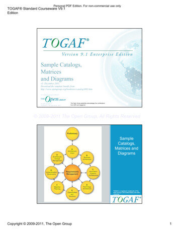
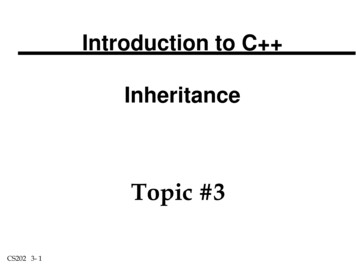
UML Tutorial for C - Windows PlatfoormGDPro 5.0Chapter 6: Class DiagramThe Class DiagramUsing the Class Diagram model, you describe the static structure of the symbols in your new system. Thismodel allows you to graphically represent symbol diagrams containing classes. Classes are arranged inhierarchies sharing common structure and behavior and are associated with other classes.Drawing ClassesClasses define the attribute values carried by each symbol instance and the operations that each symbolperforms or undergoes. When representing a class, you:Draw a class symbolName the classesEnter class attributesEnter class operationsAdd links and associationsAdd notationsAfter you have completed the step-by-step procedure outlined in the tutorial, your class diagram shouldlook similar to the following example.Note: The diagram shown above is for reference only. Use the instructions beginning on the nextpage to draw your Class diagram.-1 2000 Advanced Software Technologies, Inc.
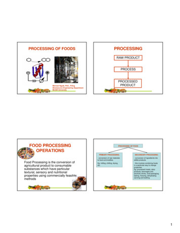
UML Tutorial for C - Windows PlatfoormGDPro 5.0Creating a Class Diagram from the Package DiagramThe class diagram can be automatically created from the package diagram.1.Make sure the package diagram called "CLD 1 - Banking" is the current diagram.2.Right-click on the Member Institutions package (do not right-click on the diagram background) andthe Package background menu opens.3.Choose CREATE ASSOCIATED DIAGRAM- MANUAL- CLASS DIAGRAM. The Class DiagramName dialog box opens. This diagram box shows the diagram type (class), the default diagramname (CLD #1 - MemberInstitutions). You can edit this name but for purposes of the tutorial we willleave it CLD #1 - Member Institutions. You can also edit the description of the diagram.4.Click. The Class Diagram Name dialog box closes and Diagram Window opens with aClass Diagram labeled CLD 1 - MemberInstitutions. The Diagram Window is empty.-2 2000 Advanced Software Technologies, Inc.
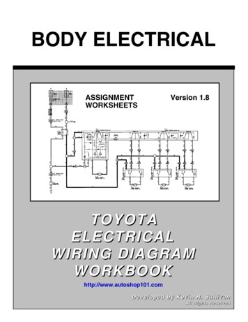
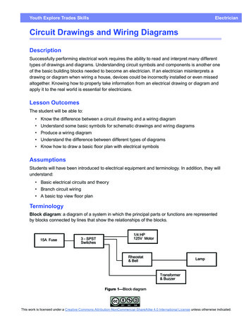
UML Tutorial for C - Windows PlatfoormGDPro 5.0Note: The diagram you just created is now the active design model. When the Class model iscreated, the Diagram Window displays a palette with icon symbols used to create classdiagrams.The Class Diagram PaletteEach icon on this palette represents a notation used to create a class diagram. Some of the objects haverelated symbols. This is indicated by a triangle located in the lower right corner of the symbol icon. Clickon the triangle and hold down the mouse button; a pull-right menu appears showing the available symbol.Slide the cursor to the symbol you want to use and the selected icon now appears on the diagram palette.IconNotationClassDefinitionA “type” of objectInstantiated into an objectDescriptor for a set of objects with thesame structure, behavior andrelationships-3 2000 Advanced Software Technologies, Inc.
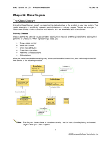
UML Tutorial for C - Windows PlatfoormTemplate ClassGDPro 5.0Template is an abstract Class that iscommonly used to define a collection typeof object.contains the same information as aClassrequires an attached TemplateParameter Labelprovides the names and possible typeof the parameters used by theTemplateUtility ClassA utility class is set of global variablesand procedures that have beengrouped in the form of a classdeclaration.It is a named collection of non-memberattributes and operations scoped bythe class.A utility class represents a type thathas no instances.The attributes and operations of theutility become global variables andprocedures.InterfaceAn interface is a specifier for the externallyvisible operations of a class, component, orother entities such as packages. Eachinterface often specifies only a limited partof the behavior of an actual class. Aninterface is formally equivalent to anabstract class with no attributes and nomethods and only abstract operations.Characteristics of interfaces:the internal structure is not specifieddo not have implementationlack attributes, states, or associationsonly have operationsmay have generalization relationshipsIconix BoundaryClassActors use boundary objects incommunicating with a system.-4 2000 Advanced Software Technologies, Inc.
UML Tutorial for C - Windows PlatfoormGDPro 5.0Iconix ControlClassControl objects serve as the glue betweenboundary objects and entity objects. Theseobjects connect the user to the stored data.Iconix EntityClassEntity objects are usually objects from thedomain model. These objects often map todatabase tables and files.ObjectAn object represents a particularinstance of a class.You name the object, the name of theclass of the object, and if applicable,the name of the package in which theobject element can reside.If the class of the object is scoped, thescope name of the class is required,an example of this would be,Package1 ClassA.You can define object attributes andset the multiplicity of the object(single/multiple).InstantiatedTemplate ClassTemplate classes are models of classes.They correspond to the generic classes ofEiffel, and to the templates of C . Atemplate class must be instantiated before itcan be used. You must instantiate it inorder to obtain a real class that must in turnbe instantiated to produce objects. Duringinstantiation, actual parameters customizethe real class based on the template class.Template classes facilitate the constructionof universal collections typed byparameters.Template classes are most often used indetailed design, to incorporate reusablecomponents, for example, beforeinstantiation the formal parameter appearsin the dotted rectangle of the templateclass, afterwards, the actual parameter isjoined to the name of class obtained byinstantiation.PackageA package scopes the name of all of itsmembers. A namespace package willimplement a true name space in thegenerated code. Otherwise, the package isused for organization and name scoping.The Package symbol is used in the UseCase, Class, and Component diagrams. Apackage is a grouping of model elements.Packages themselves may be nested within-5 2000 Advanced Software Technologies, Inc.
UML Tutorial for C - Windows PlatfoormGDPro 5.0other packages. A package may containboth subordinate packages and ordinarymodel elements. Some packages may beSubsystems of Models. The entire systemdescription can be thought of as a singlehigh-level subsystem package witheverything else in it.Design PatternPatterns describe small, recurring entities,reusable on a day to day basis in order toresolve specific problems. These patternsdo not express the general form of anapplication.This symbol is available in the followingdiagrams: Use Case, Class, Collaboration,Deployment, and Component.GeneralizationLinkGeneralization is the taxonomic relationshipbetween a more general element and amore specific element that is fully consistentwith the first element and that addsadditional information. This link is alsoknown as a specialization or tionDrawing a line between the associatedclasses represents associations.Associations represent structuralrelationships between classes and can benamed to facilitate model understanding.An association symbolizes a piece of-6 2000 Advanced Software Technologies, Inc.
UML Tutorial for C - Windows PlatfoormGDPro 5.0information with a life cycle that is nonnegligible in comparison to the generaldynamics of object instances of theassociated ciationA ternary (n-ary) association is anassociation among 3 or more classes (asingle class may appear more than once).Each instance of the association is an ntuple of values from the respective classes.A binary association is a special case withits own notation.Characteristics:Multiplicity for ternary associations canbe specified but is less obvious thanbinary multiplicityThe name of the association (if any) isshown near the diamondRole adornments can appear on eachpath as with a binary associationThe multiplicity on a role representsthe potential number of instance tuplesin the association when the other N-1values are fixedQualifiers and aggregation are notpermittedAn association class symbol may beattached to the diamond by a dashedline. This indicates a ternaryassociation that has attributes,operations, and/or associations-7 2000 Advanced Software Technologies, Inc.
UML Tutorial for C - Windows PlatfoormQualifierGDPro 5.0A qualifier is an attribute or list of attributeswhose values serve to partition the set ofobjects associated with an object across anassociation. The qualifiers are attributes ofthe association.Characteristics:is shown as a small rectangle attachedto the end of an association pathbetween the final path segment andthe symbol of the class that it connectstoqualifier rectangle is part of theassociation path, not part of the classqualifier is attached to the source endof the association -- every target fallsinto exactly one partitionthe multiplicity attached to the targetrole denotes the possible cardinalitiesof the set of target symbols selected bythe pairing of a source symbol and aqualifier valueCommon values:“0.1” -- a unique value may beselected, but every possible qualifiervalue does not necessarily select avalue“1” -- every possible qualifier valueselects a unique target symbol,therefore the domain of qualifier valuesmust be finite“*” -- the qualifier value is an index thatpartitions the target symbols intosubsetsthe qualifier attributes are drawn withinthe qualifier box. There may be one ormore attributes shown one to a linequalifier attributes have the samenotation as class attributes, except thatinitial value expressions are notmeaningfulYou can have a qualifier on each endof a single association-8 2000 Advanced Software Technologies, Inc.
UML Tutorial for C - Windows PlatfoormGDPro 5.0RealizeA realization is a semantic relationshipbetween classifiers - one classifier specifiesa contract that another classifier guaranteesto carry out. These relationships are usedin two places: between interfaces and theclasses that realize them, and between usecases and the collaboration that realizethem.ObjectAssociationJust as associations relate classes,symbols are related by links. A link is aninstantiation of an association.Dependency LinkThe dependency link is a semantic relationbetween the source and target elements. Itindicates that when there is a change to thetarget element there may be a changenecessary to the source element. You canlabel the dependency link and set thestereotype.AssociationClass LinkAn Association Link usually helps furtherdefine a many to many relationship.Association that has attributes,operations and other associationsLink is shown as a dashed linebetween the association and the Classdefining the attributes and operationsThere are no specific properties for thelinkPattern MemberLinkUsed to show the member classes orsymbols participating in a pattern.Binary ConstraintThe binary constraint notation is availableon all diagram palettes. A constraint is asemantic relationship among modelelements that specifies conditions andpropositions that must be maintained astrue. Otherwise the system described by themodel is invalid. Certain kinds of constraints(such as association "or" constraint) arepredefined in UML, others can be userdefined. A constraint represents semanticinformation attached to a model element,not just a view of it.A binary constraint allows a constraint to bedefined between any symbols on thediagram. The binary constraint allows theconstraint to be defined on the link ratherthan in a note symbol. If there is a need fora single constraint or three or more wayconstraint, then a note symbol is used to-9 2000 Advanced Software Technologies, Inc.
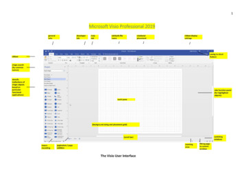
UML Tutorial for C - Windows PlatfoormGDPro 5.0explain the constraint and the note symbolis linked to the constrained symbols using anote link.Note LinkThe note link notation is available on alldiagram palettes. Use this link to connectthe note to the symbolNote PadThe note pad notation is available on alldiagram palettes. The note pad can beused to record information for a symbol orlink in a diagram. This information is notincluded in generated code but is forinformation only. Each note pad cancontain unlimited text, and be numbered.You can also define a stereotype, and entera noted element.The EntryStation ClassThe first class you will draw in the current diagram is the "EntryStation" class.1.From the Class Diagram palette select the Class symbol icon.2.Position the cursor in the top middle portion of the drawing area and click. The class symbol isplaced on the design area. When you first place the symbol, it is drawn at its default size. Thesymbol expands or shrinks to fit any inserted text.Entering Data in a SymbolThere are three methods that can be used to name the symbol. The first method is outlined below:1.Once you place the class symbol you can begin typing immediately without opening a dialog box or apop-up editor. When you do this the ClassIdentifier pop-up editor opens with the cursor in theClassName text box.2.Type the name "EntryStation" and press Enter. The Class Identifier pop-up editor closes and the unnamed text is replaced with the label "EntryStation". This is the fastest, most efficient methodof entering data and can be used on any symbol.Note: Depending on the symbol, a text box may open instead of a pop-up editor. Enter the text andclick anywhere outside the text box.-10 2000 Advanced Software Technologies, Inc.
UML Tutorial for C - Windows PlatfoormGDPro 5.0We will demonstrate the other method for naming the class symbols later.To Represent the Attributes of the EntryStation ClassNow that you have drawn the EntryStation symbol and named it, you need to describe its attributes. Theattributes for this class are Station id, and interface. There are no operations for this class.1.Click in the Attributes section (center section) of the "EntryStation" class symbol to select the classsymbol.2.Click once again in the Attributes section and an Attributes pop-up editor opens.3.Type “StationID” in the Name text field.4.Tab to the Type text field and click the drop-down arrow. A drop-down menu opens.5.Select "int" from the drop down list. The drop-down list closes and "int" appears in the Type text box.6.Press the Enter key. An empty pop-up editor is displayed.-11 2000 Advanced Software Technologies, Inc.
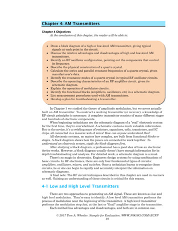
UML Tutorial for C - Windows PlatfoormGDPro 5.07.Type “isOperating” in the Name text field.8.Type “boolean” in the Type text field and click anywhere on the drawing area to close the pop-upeditor. The attributes appear in the class symbol.This method of entering attributes is called direct entry.The Remaining ClassesThe next classes you will draw are the ATM, Consortium, CashierStation, Branch and User classes. Wewill use the other two methods to name these classes.To represent the Classes:1.Double-click on the Class iconto place multiple symbols.2.Using the cursor, click your drawing area five times to place the other five class symbols as shown inthe following diagram.Note: All of the symbols can be rearranged in the drawing area if required.3.Deselect the class symbol icon by clicking the cursor iconor pressing ESC.located by the Class Diagram paletteUsing the Properties EditorsUsing the dialog box is the second method for entering attributes. However, you will probably use thedirect entry method most of the time.1.Double-click in the top section of the class symbol that will become the "ATM" class. The PropertiesEditor for Class dialog box opens.-12 2000 Advanced Software Technologies, Inc.
UML Tutorial for C - Windows PlatfoormGDPro 5.02.Enter the name “ATM” in the ClassName text field.3.Click the Attributes tab and the Properties Editor for Class dialog box opens.4.Clickand the Details portion of the properties editor opens.-13 2000 Advanced Software Technologies, Inc.
UML Tutorial for C - Windows PlatfoormGDPro 5.05.Enter “cashOnHand” in the Name text field.6.Enter “float” in the Type text field7.The default setting for Visibility is "internal" which appears as a minus sign in front of the attribute inthe class symbol. We will not change this default setting for this tutorial.8.Click. The Details properties dialog box closes and the information you enteredappears in the Attributes dialog box.Note: Do not close the Properties Editor dialog box. We will make one more entry.Continue Entering Attributes1.Clickonce again in the Attributes section. Another New Attributes dialog box opens.2.Enter “dispensed” in the Name text field.3.Click the drop-down arrow located to the right of the Type text box and a drop down menu opens.Select “float” from the list and the drop down menu closes.-14 2000 Advanced Software Technologies, Inc.
UML Tutorial for C - Windows PlatfoormGDPro 5.04.Leave the default setting of "internal" for Visibility.5.Click. The New Attributes properties dialog box closes and the information you enteredappears in the Attributes dialog box.6.Click the Documentation Tab in the same properties editor dialog box and the related dialog boxopens.7.Enter the text "Describes the actions of the ATM cash dispensing machine" in the Description textbox.8.Clickto close the Properties Editor dialog box. The attributes appear in the ATM classsymbol. However note that the description you entered does not appear in the class symbol itself. Itdoes appear in the Documentation Pane located in the bottom left corner of the GDPro window.Note: Notice that the size of the class symbol adjusts to fit the text entry.Using the Documentation PaneAs you create diagrams, the symbol you are working on appears in the Documentation Pane. This paneallows you to view the operations and attributes of the symbol. You can also view and/or modify thedescription of the model element.-15 2000 Advanced Software Technologies, Inc.
UML Tutorial for C - Windows PlatfoormGDPro 5.0The description you entered for the ATM class symbol appears in the lower portion of the DocumentationPane. You can edit or add additional information in this text box.1.Enter the text "These are stand-alone ATMs." in the Documentation Pane Description text box.2.Double-click on the ATM class symbol to open the Properties Editor for Class ATM dialog box. Clickthe Documentation Tab. The text that you entered in the Documentation Pane also appears in theProperties Editor dialog box.3.Click OK to close the Properties Editor dialog box.All attributes and operations that you add to the class symbol appear in the upper portion of theDocumentation Pane. The attributes are represented by an attribute symbol. The operations arerepresented by.1.Click on the attribute "cash on hand" in the Documentation Pane to select it. The description portionof the pane is now labeled "cash on hand".2.Enter the text "maintains a balance of available cash".3.Double click the ATM symbol to open the Properties Editor. Click the Attributes Tab and then selectthe "cash on hand" attribute in the list box.4.Click the Edit button and the Attribute Editors for cash on hand dialog box opens.5.Click the Documentation Tab and the description you entered in the Documentation Pane appears inthis description text box.-16 2000 Advanced Software Technologies, Inc.
UML Tutorial for C - Windows Platfoorm6.Clickmain dialog box.GDPro 5.0twice, once to close the New Properties Editor dialog box, and once to close theUsing the Background Menu to Enter DataYou can use the background menus as a third method of entering data in a symbol.1.Right-click the class symbol that will become the "Consortium" class. The Class background menu isdisplayed.2.Choose Properties from the menu. The Properties Editor for Class dialog box opens.3.Enter the name “Consortium” in the ClassName text field.4.Click the Operations tab and the Name portion of the dialog box opens.-17 2000 Advanced Software Technologies, Inc.
UML Tutorial for C - Windows PlatfoormGDPro 5.05.Clickand the Details portion of the Properties Editor dialog box opens.6.Enter the text "validateAccountInfo" in the Name text box. There is no Return Type for thisoperation.7.The default setting for Visibility is "public" which appears as a plus sign in front of the operation in theclass symbol. We will not change this default setting for this tutorial.8.Click9.Clickin the Operations dialog box. The dialog box closes and text is entered into the"Consortium" class symbol. The Details dialog box closes and the text appears in the Name dialog box.Note: There are no attributes for the "Consortium" class symbol.To Complete the Remaining Class SymbolsWe will use the “direct entry” method to complete the remaining Class symbols but you may use any ofthe methods you prefer.1.Position the cursor over the text unnamed in the Class symbol that will become the"CashierStation" class and click once to select the symbol. Click once again and the Class Identifierpop-up editor opens.-18 2000 Advanced Software Technologies, Inc.
UML Tutorial for C - Windows Platfoorm2.GDPro 5.0Enter the name "CashierStation" and click anywhere outside the pop-up editor. The pop-up editorcloses and the name “CashierStation” is entered in the top section of the Class symbol.Enter Operations Attributes1.Click in the operations section (bottom section) of the "CashierStation" class symbol. AClassOperations pop up window opens.2.Enter “verifyCard” in the Name text field.3.Tab to the ReturnType text field and enter “int” in the text field. Press Enter and a new Operationspop-up editor opens.4.Enter “verifyAmountAvailable” in the Name text field.5.Enter “float” in the ReturnType text field and click anywhere outside the pop-up editor. The pop-upeditor closes and the operation appears in the bottom section of the class symbol.Enter Name for the Branch and User Classes1.Position the cursor over the text unnamed in the Class symbol that will become the "Branch" classand click once to select the symbol. Click again and a pop-up editor opens.2.Enter the name “Branch” and press Enter. The name “Branch” is entered in the top (name) sectionof the Class symbol.3.Click in the attributes section (center section) of the Branch class symbol. An Attributes pop-upeditor is displayed.4.Enter “String” in the Name text field.5.Enter “char” in the Type text field and click anywhere outside the pop-up editor. The pop-up editorcloses and text is entered into the Branch class symbol. There are no operations for this classsymbol.-19 2000 Advanced Software Technologies, Inc.
UML Tutorial for C - Windows Platfoorm6.GDPro 5.0Following steps 1 through 2, enter the class name "User" for the last unlabeled class symbol. Thisclass has no attributes or operations.Depicting a Qualified AssociationA qualified association relates two symbol classes and a qualifier. The qualifier is a special attribute thatreduces the effective multiplicity of an association. You depict a qualified association as a small box onthe end of the association line near the class it qualifies.The qualified association you are about to depict is between the "ATM" class and the Consortium class.To depict a qualified association:1.From the Class Diagram palette select the Qualifier icon. Note that this icon is located on thepull-down menu located under the Class Association Icon2.Position the cursor near the top edge of the "Consortium" class symbol and click. The qualifiersymbol appears and is attached to the "Consortium" class symbol.Note:You know the qualifier symbol is attached to the class symbolbecause the "handles" around the qualifier symbol are blue onceyou place it on the diagram. If there is no relationship, thehandles are black-20 2000 Advanced Software Technologies, Inc.
UML Tutorial for C - Windows PlatfoormGDPro 5.0Naming a Qualified Association1.Double-click the Qualifier. The Properties Editor for Qualifier dialog box opens.2.Double-click in the Label portion of the text box. Enter “Stationed” in the text box and click. The dialog box closes and the text is entered in the Qualifier box attached to theConsortium class symbol.Identify AssociationsAn association describes a group of links with common structure and common semantics. All the links inan association connect symbols from the same classes.GDPro not only allows for associations but also multiplicity of associations. Multiplicity specifies howmany instances of one class may relate to a single instance of an associated class. Multiplicity constrainsthe number of related symbols.Role names are also supported and provide a way of traversing associations from an symbol at one end,without explicitly mentioning the association. Role names are often used for associations between twosymbols of the same class.-21 2000 Advanced Software Technologies, Inc.
UML Tutorial for C - Windows PlatfoormGDPro 5.0Class Associations1.Select the Class Assocation-Aggregationfrom the Class palette pull-down menuKey: Because LAYOUT- ORTHOGONAL LINKS is selected from the menu the links automaticallyadjust to right angles when completed.Note: If you did not select Orthogonal Links command before drawing the link you can square thelink after it is drawn as well. Select the link to be squared and choose LAYOUT- CHANGELINE STYLE- ORTHOGONAL LINK MODE from the menu. The selected link adjusts to rightangles.2.Click inside the bottom of the "ATM" class symbol. Drag the cursor down inside the top portion ofthe Station Code Association Qualifier symbol and click once again. A valid link is drawn betweenthe two classes.-22 2000 Advanced Software Technologies, Inc.
UML Tutorial for C - Windows Platfoorm3.GDPro 5.0Select the AssociationLinkfrom the draw-down menu and draw an association link from theCashierStation class to the Branch class.Note: You can also change the Association by using the Enumerated Values commandLabeling the Class Association1.To label the class association between the ATM and Consortium classes, double-click theassociation link. The Properties Editor dialog box opens.-23 2000 Advanced Software Technologies, Inc.
UML Tutorial for C - Windows PlatfoormGDPro 5.02.Enter the name "AccountVerification" in the Name text box.3.Leave the Properties Editor dialog box open to set the Role Multiplicity for this association.Role Multiplicity for the First Association1.Under the Role 1 tab, enter a "1" in the LowerBound text box.2.Enter an "*" in the UpperBound text box.3.Under the Role 2 tab enter a "1" in both the LowerBound and UpperBround text boxes.4.Click, the Association dialog box closes and the association symbol is labeled.-24 2000 Advanced Software Technologies, Inc.
UML Tutorial for C - Windows PlatfoormGDPro 5.0Note: You can reposition the AccountVerification label by placing the cursor on the label and whileholding down the mouse button, move the label. Release the mouse button when the label isin place.Setting the Role Multiplicity for the Second Association1.Double-click on the Association symbol between the "CashierStation" class and the "Branch" classsymbol. The Properties Editor for Association dialog box opens.2.Under the Role 1 tab, enter an "*" in the UpperBound text box.3.Under the Role 2 tab, enter "1" in the LowerBound and UpperBound text boxes.4.Click. The Properties Editor dialog box closes and the ClassAssociation link is labeled.-25 2000 Advanced Software Technologies, Inc.
UML Tutorial for C - Windows PlatfoormGDPro 5.0Depicting Generalization and InheritanceGeneralization is the relationship between a class and one or more refined versions of this class. Theclass being refined is called the superclass and each refined version is called a subclass. The attributesand operations of the superclass can be exhibited in its subclasses; as a result, each subclass is said toinherit the features of the superclass. Organize classes by using inheritance to share common structure.When representing a generalization, you draw the generalization links, attaching them to the desiredsubclasses.The generalizations you are about to depict are between the EntryStation class (superclass) and the"ATM" and "CashierStation" classes (subclasses).Draw Generalization Links1.From the Class Diagram palette, double-click the Generalization Link symbol icon.2.Click in the ATM class symbol and drag the cursor up to the lower portion of the EntryStation classsymbol and click again. A generalization link snaps in place between the two class symbols.3.Click in the CashierStation class symbol and drag the cursor up to the EntryStation class symbol andclick again. The second generalization link symbol is drawn.Note: Because the Orthogonal Links command is selected from the Layout menu, thegeneralization links will be squared automatically.4.Deselect the Generalization Link symbol icon by clicking the cursor iconDiagram palette or press the ESC key.located by the Class-26 2000 Advanced Software Technologies, Inc.
UML Tutorial for C - Windows PlatfoormGDPro 5.0Adding Notes to the Diagram1.Click the Note Pad iconin the Class Diagram Palette.2.Place the cursor to the right and just above the CashierStation class symbol. Click once and a notepad symbol is placed on the diagram.3.Double-click the note symbol and the Properties Editor for Note Pad dialog box opens.4.Enter the number "1" in the Number text box.5.We will leave the Stereotype setting as "Notation" for this tutorial.6.Click inside the Text box and enter the following text: "Cashier stations have" and press the Enterkey. The cursor advances to the next line in the text box.7.Enter the text "limited funds" and clickNote pad is populated. The Properties Editor dialog box closes and the-27 2000 Advanced Software Technologies, Inc.
UML Tutorial for C - Windows PlatfoormGDPro 5.08.Click the NoteLink iconin the Class Diagram palette.9.Click once inside the NotePad symbol, drag the cursor to inside the Cashier Station symbol and clickagain. The link snaps in place betw
UML Tutorial for C - Windows Platfoorm GDPro 5.0-3- 2000 Advanced Software Technologies, Inc. Note: The diagram you just created is now the active design model. When the Class model is created, the Diagram Window displays a palette with icon symbols used to