Transcription
Project Number: JMS – 010AThermal Design of a Fire GrateA Major Qualifying Project:Submitted to the Faculty of theWORCESTER POLYTECHNIC INSTITUTEIn partial fulfillment of the requirements for theDegree of Bachelor of ScienceBy:Alexander P. TutoneDate: April 29, 2010Approved By:Professor John M. Sullivan, Jr., Advisor
AbstractConventional wood burning fireplaces make inefficient space heating elements forresidential use. The addition of some commercial fire grates claim to increase the heatingefficiency. The purpose of this project is to test the validity of these claims using theoreticalmodels as well as experimental analysis of heat transfer. Heat transfer and fluid dynamicequations were used to model the theoretical air flow through the fire grate. A test structure wasfabricated and instrumented to gather experimental data. This data was used to compute the heatadded by the fire grate and the results were compared to the theoretical model. Thesecalculations yielded roughly 625 Watts added to the room from one, four-piped insert. This isequivalent to a 40% increase in heat production from a similar fireplace without an insert. Fromthis it is concluded that the addition of a fireplace insert similar to the one used in this projectwith a blower attachment is beneficial for space heating.2
AcknowledgmentsI would like to thank Professor John M. Sullivan for all of the guidance andpatience he provided throughout this project. I would also like to extend my thanks to NeilWhitehouse for use of his lab as well as his guidance with the design. Finally I would like tothank Randall K. Harris, and Toby Bergstrom without whom the testing could not have beencompleted.3
Table of ContentsAbstract . 2Acknowledgments. 3Table of Figures . 5Table of Equations . 6Introduction . 7Methodology. 23Results . 35Conclusions . 41Works Cited . 434
Table of FiguresFigure 1: Schematic of U.S. Patent 4,010,729 ‐ Example of a Horizontal Fireplace Grate with Blower (Egli,1975) . 8Figure 2: Side View Schematic of U.S. Patent 4,129,113 ‐ Example of a Vertical Fireplace Grate with GlassDoor Faceplate (Bergstrom, 1977). 9Figure 3 : SolidWorks Rendering of Fireplace Grate "C Pipe" . 12Figure 4 : SolidWorks Rendering of Pipe Securing Clamp . 13Figure 5 : SolidWorks Rendering of Fire Grate Support Legs Concept . 13Figure 6 : Thermocouple Schematic . 16Figure 7 : Cross Section View of Test Rig with Thermocouple Placement . 24Figure 8 : Outer Thermocouple Configuration Close Up . 25Figure 9 : Inner Pipe Thermocouple Layout . 26Figure 10 : Inner Pipe Midflow Thermocouples Located Near Pipe Entrance . 26Figure 11 : Midflow Thermocouples Located Near Pipe Exit . 27Figure 12 : Upper Midflow Thermocouples Secured via Furnace Paste . 27Figure 13 : Entire Test Rig . 28Figure 14 : Testing Configuration . 29Figure 15 : Data Acquisition Board Used During Testing . 29Figure 16 : Labeled BNC Cables Attached to DAQ Board . 30Figure 17 : Screw Terminal Thermocouple Wiring . 31Figure 18 : VI Front Panel . 32Figure 19 : VI Block Panel . 34Figure 20 : 250C Test Temperature vs. Time . 36Figure 21 : 300C Test Temperature vs. Time . 37Figure 22 : 400C Test Temperature vs. Time . 375
Table of EquationsEquation 1 : Rate of Net Radiation Heat Transfer Per Unit Area Between Two Surfaces (Cengel, Turner,& Cimbala, 2008). 15Equation 2 : Relationship between Reynolds Number and Flow Velocity (Cengel, Turner, & Cimbala,2008) . 18Equation 3 : Estimated Heat Loss up Chimney Flue (Part 1) . 19Equation 4 : Estimated Heat Loss up Chimney Flue (Part 2) . 20Equation 5 : Estimated Heat Loss up Chimney Flue (Part 3) . 21Equation 6 : Estimated Heat Loss up Chimney Flue (Part 4) . 22Equation 7 : Estimated Heat Loss up Chimney Flue (Part 5) . 23Equation 8 : Heat Transfer Equations (Kreith & Black, 1980) . 39Equation 9 : Heat Transfer Calculations (Peacock, 1987) . 406
IntroductionFireplaces are a common commodity in residential American homes, and are used bothfor aesthetic purposes and as a source of space heating. Unfortunately, a fireplace can be a veryinefficient source of heat since large quantities of heat and residential air exit via the chimney.While fireplace inserts are readily available to the general public, the claims that they provide asignificant increase in the heat output of the fire are not supported with quantitative, publiclyavailable data. The purpose of this project is to model the heat and fluid flow of a fireplace,construct and instrument a fireplace grate, and analyze the data collected to measure the quantityof mass flow and heat being exchanged. These results are compared to simplified theoreticalestimates of the fireplace system.The background research included benchmarking research of fireplace inserts, typicaldimensions of fireplaces, and typical costs for space heating in New England. The results aresummarized subsequently.Fireplaces are a common commodity in American homes. In 1997 it was estimated thatthere were 27 million fireplaces nationwide that were used as a primary space heating source(Kochera, 1997). More than 7 million of these installations utilized a fireplace insert to increasethe efficiency of heat output (Bucklin Smith & Associates, Inc., 1989-1996). This is due to thefact that a fireplace alone is a very inefficient source of heat since all or most of the heatgenerated by the burning of the wood flows out via the chimney. Fire grates are designed tomitigate this loss in heat using various techniques.Fire grates are readily available for purchase to the general public. A patent review wasconducted to better understand their function as well as their advantages and disadvantages. Afire grate is typically a series of metallic tubes that lie within close proximity to a fire's logs and7
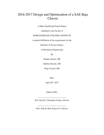
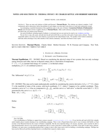
have inlets and outlets that allow for air exchange with the room containing the fireplace.The two main types of fire grates consist of vertical and horizontal grates. Horizontalgrates, like the one described in U.S. Patent 4,010,729 places the inlet and outlet of the gratehorizontal with respect to each other. A schematic of this patent is provided in Figure 1: Schematicof U.S. Patent 4,010,729 ‐ Example of a Horizontal Fireplace Grate with BlowerFigure 1. The logs sit atop thepiping, heating the air which, in this case, is being pumped through via a small squirrel cageblower.Figure 1: Schematic of U.S. Patent 4,010,729 ‐ Example of a Horizontal Fireplace Grate with Blower (Egli, 1975)One advantage of a horizontal blower is its shape does not need to be changed for variousfireplaces. By adding variable length piping for inlet and outlet sections, as done in patent4,010,729, the grate compensates for fireplaces that have varying depths. However, horizontalgrates receive all or most of their heat transfer from the conduction between the logs and the8
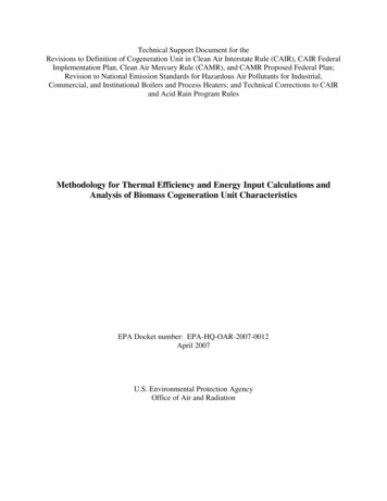
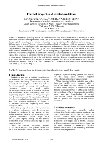
piping. A disadvantage to a horizontal grate is the requirement of a blower to induce air flowthrough the grate. While squirrel cage blowers are small, they are not as aesthetically pleasingdue to noise generation. This design also requires electricity to operate which iscounterproductive to increasing heating efficiencies.The second common fireplace insert orients the inlet and outlets vertically with respect toone another. These vertical fire grates tend to be shaped roughly like a "C" and typically consistof several pipes configured parallel to each other. They are arranged in such a way that theyextend back into the fireplace then climb quasi-parallel to the back wall, then angle back towardthe room. Patent 4,129,113 clearly displays the typical layout of a vertical fireplace grate inFigure 2.9
Figure 2: Side View Schematic of U.S. Patent 4,129,113 ‐ Example of a Vertical Fireplace Grate with Glass Door Faceplate(Bergstrom, 1977)The grate seen in Figure 2 features a glass door facade for aesthetic and heat conservationpurposes. Vertical grates offer many advantages over horizontal inserts. One advantage is thatvertical grates receive heating not only from conduction between the logs and the piping but alsosignificant radiation heating since the piping surrounds the fire more completely. Anotheradvantage vertical grates have over horizontal ones is that natural convection helps drive the airflow through the piping eliminating the need for a blower. A blower can still be attached toattain greater flow velocities if desired. The major disadvantage of vertical fireplace grates istheir restricting shape. The back wall of most fireplaces are not strictly vertical but rather angleout toward the room halfway up the wall. This requires the piping to be angled similarly in orderto fit within the fireplace. This can cause the shape to vary slightly for each fireplace.10
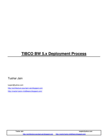
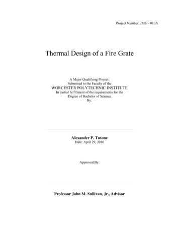
Masonry fireplaces come in a variety of sizes from about 0.64 meters to as much as 1.2mwide, by roughly 0.61m to 0.91m high, and 0.20m to 0.56m deep. For our considerations, thefirebox dimensions are assumed to be 0.61 m wide, by 0.76m tall, by 0.45m deep. Fire wood thatis burned in such fireplaces is typically sold in 16 inch long pieces. However, while a fire isburning, the outer portion of the logs is not burning as hot as the center of the fire. Therefore, forcalculation purposes, the heat source dimensions will be assumed 0.23 m long by 0.15 m tall.For this project, a vertical fireplace grate was designed similar to the one depicted inFigure 2. This was chosen because of the natural air flow produced removed the requirement fora blower to produce flow through the pipes. This fire grate consists of several metallic pipesfitted together such that they fit within a fireplace and will function as a stand for logs to situpon. These pipes are open to the room in such a manner that the air within them can be heatedvia the burning logs. This heated air, through natural or forced convection, flows out into theadjacent room supplying additional heating to the room.This grate was fabricated out of black galvanized steel malleable iron piping purchased ata local Home Depot store. The ends of the individual pieces are threaded in such a way thatassembly simply consists of screwing together adjacent pieces together. This allows for easyaccess to the interior of the piping for placement of temperature reading devices.A Computer Aided Design (CAD) model was built to visually represent the design for thefire grate. This was done in SolidWorks Education Edition. The piping that makes up the Cshape is shown in Figure 3. The lengths of each segment are suitable such that it would fitwithin a standard fireplace. The bottom portion of the tubes is divided into segments to provideaccess to the interior for test instrumentation. The 90 degree elbow would likely be placed such11
that is touching the back of the firebox of the fireplace. A 45 degree elbow is placed above the90 degree elbow to accommodate for the slanted back walls of fireplaces. A second 45 elbow isintroduced to redirect the air flow back out into the room. The design is built such that theentrance and exit pipes extrude out into the room roughly 0.05 m so as to avoid mixing of thedesired heated air with toxic fumes from the fire. The overall assembly would consist of four ofthese pipes placed next to each other.Figure 3 : SolidWorks Rendering of Fireplace Grate "C Pipe"These pipes were designed to be held up by a bracket device that is bolted together usingbolts similar to those shown in Figure 4. These clamps will be bolted into a plate of metal toconnect adjacent tubes together. The end clamps in turn will be bolted onto legs as can be seen12
in Figure 5. These legs would keep the logs elevated above the floor to promote increased airflow as well as keep the unburned logs from being smothered by the ash that collects below thefire.Figure 4 : SolidWorks Rendering of Pipe Securing ClampFigure 5 : SolidWorks Rendering of Fire Grate Support Legs ConceptThis assembly is meant to be inserted into the fireplace such that the logs to be burntwould be placed on top of the C-shaped pipes. The burning of the logs provides heating to theair contained within the tubes thus producing a flow.13
There are three basic methods of heat transfer: convection, conduction, and radiation.Convection heat transfer occurs whenever fluids flow over a solid of a different temperature thanthat of the fluid. In all cases heat will transfer from the hotter entity to the cooler one accordingto the second law of thermodynamics. Similarly, conduction heat transfer refers to the flow ofheat from a hot surface to that of a cooler surface that is touching the heated surface. In this wayconduction only applies when there is physical contact between two surfaces and a temperaturegradient exists. Radiation, the third mode of heat transfer, occurs at all times between all objectsthat are of differing temperatures. Any hot surface radiates heat based on the temperaturegradient between the hot surface and its surroundings.There is no air flow from an open fire into a room and those enjoying its warmth so wecan reason that the heat transfer due to convection is negligible. Indeed, if there were significantflow from the fire into the room, it would be filled with toxic chemicals contain within the smokeand as such air usually flows from the room and into the fireplace. Similarly, open fires havenegligible effects on heating a room via conduction since the on physical contact is betweenmolecules of air which are so fleeting and random they are practically zero. It can thus bereasoned that the only significant heat transfer that occurs between an open fire and the adjacentroom is due to radiation.With this knowledge of heat transfer and its corresponding equations we can predict thebehavior of a fireplace grate quantitatively. This allowed us to quantitatively estimate the heattransfer of a grate system using well established governing physics.A fire puts out a significant amount of heat per second when burning at full force. It canbe assumed that the amount of heat felt by a human standing three feet away from a fire is14
comparable to the amount of heat felt if that person was standing three feet away from a 1500watt resistance heater. If we take this comparison to be true, we can assume that a fire radiatesroughly 1500 watts of heat out into a room. The fire radiates heat in all directions at all times,however we assume that the portion of heat radiated felt by the human is within a 45 degreeangle. With these assumptions we can calculate the expected temperature at which the fire burnswithin the fireplace if the ambient temperature of the room is 21 degrees Celsius.15
Equation 1 : Rate of Net Radiation Heat Transfer Per Unit Area Between Two Surfaces (Cengel, Turner, & Cimbala, 2008)This value of how hot the fire burned gave a temperature to aim for when performingtests. This value is also backed by findings of masonry fireplace studies (Peacock, 1987). It alsoallowed for a thermocouple to be chosen for temperature data collection when testing the gratesystem.16
Thermocouples are one of the most of common means of measuring the temperature ofspecific points in a system because they are compact, durable, repeatable and have a fasttemperature response time. They utilize the Seebeck effect which converts thermal energy toelectrical energy. The thermal energy is in the form of a change in temperature at one nodewhich creates a voltage within the loop. The setup used in my project consists of a thermocouplemade of two different metals that are joined by a third metal to create a junction. This junction isplaced in the environment where temperature is to be measured. The two metals are joined at asecond junction, typically copper which connects the thermocouple to a digital data reader. Aslong as the two metals making up the thermocouple remain at the same temperature at the copperjunction, there will be no interference with the reading. This setup is illustrated in Figure 6obtained from the Maxim website on thermocouple basics (Maxim Integrated Products, 2007).Figure 6 : Thermocouple SchematicThe copper junction is known as the cold junction while the measured junction is calledthe hot junction. The voltage read by the digital data reader is found by multiplying thetemperature difference between the two junctions by a scaling factor α, called the Seebeckcoefficient. This value can be looked up using reference tables. According to the equation at thebottom of Figure 6, the only way of finding the voltage change is to know the temperature at thecold junction. An easy way to know this reference temperature is to create an ice bath. However17
since ice baths are not practical in most environments, one can use the ambient temperature atthe cold junction. Unfortunately this introduces another voltage into the loop which must becompensated. This compensation is called the cold junction compensation or CJC. Without thiscompensation, there would be an inherent error in all readings because the voltage being readconsists not only of the voltage change from the hot junction but from the cold junction as well.The two different metals that make up the thermocouple wires are typically chosen basedon the temperatures they will be subjected to. Thermocouples come in a variety of types basedon their temperature range of operation as well as their sensitivity. Based on the predictedtemperature of a fire, a type K thermocouple was chosen. A type K thermocouple is one of themost commonly used thermocouple types because of its wide temperature range and low cost.Type K thermocouples are made of chromel (90% Ni, 10% Cr) and alumel (95% Ni, 2% Mn, 2%Al, 1% Si), can operate in environments ranging from about -200 C - 1200 C, and have asensitivity of about 41 μV/ C (Pico Technology).Using basic assumptions and simplified fluids equations, the expected velocity of the airflow exiting the room via the chimney flue can be estimated. The flow of a fluid can beclassified as either laminar, turbulent, or a mixture of the two. The flow type is determined bythe value of the Reynolds number (Re). Laminar flow is generally a very smooth flow with nodisruption or mixing motions. On the other hand, turbulent flow is very choppy with veryrandom motion of individual particles within the fluid. The Reynolds number is a function of thevelocity of the fluid flow, the geometry of the pipe/duct through which the fluid is flowing, andthe viscosity of the fluid, in such a way as subsequently defined. If the fluid velocity is assumedto have a constant profile throughout the pipe (or chimney flue) then the velocity can be depictedby the constant “u”.18
Equation 2 : Relationship between Reynolds Number and Flow Velocity (Cengel, Turner, & Cimbala, 2008)In Equation 2 dh is the hydraulic diameter of the flue, μ is the absolute dynamic viscosityof the air, and δ is the density of the air at an assumed temperature. Natural convection flows areassumed to be both turbulent and laminar in nature which corresponds to a Reynolds number ofaround 2300 (Cengel, Turner, & Cimbala, 2008). This is the point at which most viscous flowsenter the transition stage between laminar and turbulent. Therefore, by assuming a value of 2300for the Reynolds number, we can calculate the expected flow velocities of heated air up thechimney. The chimney flue diameter was estimated to be about 0.254m (10 inches) (TheEngineering Toolbox, 2005). In a study performed by Richard Peacock on masonry fireplaces,log fires were burned at steady state around 400 C with the use of a fireplace insert. Thetemperature of the air flowing through the chimney was found to be roughly 100 degrees C.Using this as an assumed temperature of the flue gasses and the Reynolds number, we canestimate the amount of heat flowing up the chimney over a period of time.19
Equation 3 : Estimated Heat Loss up Chimney Flue (Part 1)20
Equation 4 : Estimated Heat Loss up Chimney Flue (Part 2)21
Equation 5 : Estimated Heat Loss up Chimney Flue (Part 3)22
Equation 6 : Estimated Heat Loss up Chimney Flue (Part 4)23
Equation 7 : Estimated Heat Loss up Chimney Flue (Part 5)According to the previous calculations a fireplace alone might add heat to a house oreven loose heat based on damper positioning. Instead of constantly adjusting the glass doors toincrease fireplace efficiency the use of fireplace inserts can be used.MethodologyIn order to estimate the performance of commercial, convection based fire grates,physical tests were run in addition to the theoretical calculations. To this end, an individual24
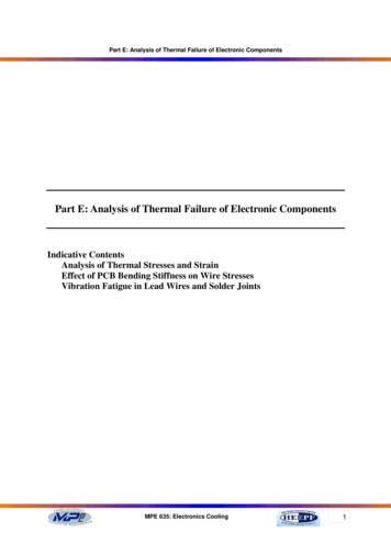
vertical grate component was constructed and tested. For time and efficiency only one C pipewas built since the results could simply be multiplied by the number of pipes. A section view ofthe C pipe built is shown in Figure 7. This figure also shows the placement of type Kthermocouples (TCs) used in testing.Figure 7 : Cross Section View of Test Rig with Thermocouple PlacementThese thermocouples were placed such that temperature readings could be taken at keylocations within the rig. Three thermocouples were attached to the outside of the piping usingIDEAL stainless steel SAE size #12 pipe clamps purchased at Home Depot. These clamps had arange of 0.5 inches to 1.25 inches. The three thermocouples were secured by using two clampsin tandem. The thermocouples were placed on the top of the pipe where the logs would sit andwere used to measure the temperature of the fire. A photo of this is available in Figure 8.25
Figure 8 : Outer Thermocouple Configuration Close UpThree more thermocouples were secured inside the piping by spot welding the hotjunctions to a smaller diameter pipe than the C pipe. This smaller pipe was then inserted untilthe thermocouples welded to it were approximately below the outer TCs. Additionally three TCswere secured such that their hot junction lied approximately in the center of the inner pipe.There were three small holes drilled into the outside of the inner pipe to provide access to thecenter. These TCs were used to take the temperature of the air midflow within the pipe. Thesemidflow thermocouples were secured to the inner pipe by use of Hercules Regular Body HighHeat Furnace Cement purchased at Home Depot. Figure 9 and Figure 10 illustrate thethermocouple placement on the inner pipe.26
Figure 9 : Inner Pipe Thermocouple LayoutFigure 10 : Inner Pipe Midflow Thermocouples Located Near Pipe Entrance27
Finally, three similar holes were drilled into the top of the rig and thermocouples wereplaced such that they could record the midflow exit temperature of the air. These TCs were alsosecured using the furnace paste. The following two figures display this setup.Figure 11 : Midflow Thermocouples Located Near Pipe ExitFigure 12 : Upper Midflow Thermocouples Secured via Furnace Paste28
This arrangement of thermocouples allowed for data to be gathered in several keylocations: the fire’s temperature (outer TCs), the approximate inner surface temperature of therig, and the entrance and exit air flow temperatures. With these temperatures known, the heattransferred to the air from the fire could be calculated.Since only one C pipe was fabricated, a propane torch was used as a heat source insteadof burning logs when running tests. The C pipe was constrained by using a table vice. Theoverall setup can be seen in Figure 13.Figure 13 : Entire Test Rig29
Figure 14 : Testing ConfigurationData was gathered using a National Instruments NI USB-6229 Data Acquisition Board(DAQ). This board can be seen in Figure 15.Figure 15 : Data Acquisition Board Used During Testing30
This board is capable of reading 16 independent sources of data at 16 bit resolution and250,000 samples per second. The thermocouples were fed into this board using BNC cables.Figure 16 : Labeled BNC Cables Attached to DAQ BoardThese cables were labeled from 1-12 according to which DAQ Board channel they usedduring testing as determined by the VI’s programming. These BNC cables were attached to thethermocouples via screw terminals and alligator clips as seen in Figure 17.31
Figure 17 : Screw Terminal Thermocouple WiringA virtual instrument (VI) was created using Lab View 8.6 to read and record the TCreadings to a Microsoft Office Excel 2007 spreadsheet. This VI was also programmed to use theTC readings and user supplied constants to calculate the amount of heat being added to the airflowing through the pipe. A screen shot of the front panel of the VI is shown below in Figure 18.32
Figure 18 : VI Front PanelThe Thermocouple Constant Controls located in the blue section of the front panelinclude user input controls such as the minimum and maximum expected temperature values, the33
cold junction reference, the thermocouple type and the units of the TC readings. The greensection contains Data Acquisition Controls such as the record to disk button, the milliseconds towait button, the STOP button as well as the file path controls. The yellow section displays theTC readings graphically and are grouped together according to the TC's location on the testingrig. For example, the left graph plots the outer TC readings as a function of time as well as theinner TC readings. Finally, the purple section contains the constants and dimensions controlsrequired to calculate the heat added to the air during testing. The accompanying graph plots thecalculated heat transfer versus time. This portion of the VI is contained within its own triggeredloop so the computer does not waste time and resources computing the heat transfer while thesystem is still heating to steady state.The block diagram in Figure 19 shows how the VI was programmed. The instrument isset up to read 12 separate channels from the data acquisition board. These readings are thenaveraged before being plotted on the front panel. These averages are also fed to the record todisk node
Masonry fireplaces come in a variety of sizes from about 0.64 meters to as much as 1.2m wide, by roughly 0.61m to 0.91m high, and 0.20m to 0.56m deep. For our considerations, the firebox dimensions are assumed to be 0.61 m wide, by 0.76m tall, by 0.45m deep. Fire wood that is burned in