Transcription
Baja SAE 2016-20172016-2017 Design and Optimization of a SAE BajaChassisA Major Qualifying Project Reportsubmitted to the Faculty ofWORCESTER POLYTECHNIC INSTITUTEin partial fulfillment of the requirements for theBachelor of Science Degreein Mechanical EngineeringByHeather Selmer, MESabbrin Shweiki, MEPaige Tencati, MEDate:April 20th, 2017Approved By:Prof. David C. Planchard, Project AdvisorProf. John R. Hall, Project Co-Advisor
Baja SAE 2016-2017Table of ContentsTable of Figures1List of Tables2List of ntroduction6Project Overview6SAE Overview7What is a Baja vehicle?8Background Research9Vehicle Subsystems9Frame9Suspension10Wheel Alignment12Methods and Procedure18Design Specifications18Design Analysis19Suspension System19Front Suspension Design21Rear Suspension Design21Transmission22Torque GoalFrameDesign Iterations222424Conclusion41Future Work and Suggestions43
Baja SAE 2016-2017Appendices44Appendix A: Baja SAE Vehicle with Subsystems44Appendix B: Elongated Design Simulations45Appendix C: Final Design Simulation Reports59C1: Frontal Impact 159C2: Frontal Impact 268C3: Rear Impact76C4: Rollover84C5: Drop Impact92C6: Side Impact100C7: Top Impact108C8: Driver and Engine Drop116Works Cited124
Baja SAE 2016-2017Table of FiguresFigure 1 Primary and Secondary Member Classification . 10Figure 2 Coil Over Shock Absorber . 11Figure 3 Air Shock Absorber . 12Figure 4 Camber angle . 13Figure 5 Caster . 14Figure 6 Toe configuration (as viewed from the top) . 15Figure 7 SAI / KPI . 16Figure 8 RIT’s 2016 Vehicle Showing Double A-Arm in the Front Suspension . 20Figure 9 Front suspension design. 21Figure 10 Rear Suspension Design . 22Figure 11 Free Body Diagram of Baja for Hill Climb Event . 23Figure 12 Rounded Square Nose Model of First Frame Design . 24Figure 13 Rounded Square Nose Model Front Impact Four Points Static Force Simulation and StressKey . 26Figure 14 Square Nose Model Close-up of Front Impact Four Points Static Force Simulation . 27Figure 15 Rounded Bottom Nose Frame Design . 27Figure 16 Rounded Bottom Nose Model Front Impact Four Points Static Force Simulation andStress Key . 28Figure 17 Rounded Bottom Model Close-up of Front Impact Four Points Static Force Simulation . 28Figure 18 Welded Square Nose Model Frame Design . 29Figure 19 Welded Square Nose Model Front Impact Four Points Static Force Simulation and StressKey . 30Figure 20 Welded Square Nose Model Front Impact Two Points Static Force Simulation and StressKey . 30Figure 21 Welded Square Nose Model Modified . 31Figure 22 Elongated Welded Square Nose Model . 31Figure 23 Elongated Welded Square Nose Model Front Impact Four Points Static Force Simulationand Stress Key . 32Figure 24 Elongated Welded Square Nose Model Front Impact Two Points Static Force Simulationand Stress Key . 32Figure 25 Elongated Frame Design with Front Tabs. 33Figure 26 Percy and C10 . 34Figure 27 Front Impact Simulation . 35Figure 28 Front Bottom Impact Simulation. 35Figure 29 Rollover Simulation. 36Figure 30 Rear Impact Simulation . 36Figure 31 Top Impact simulation . 37Figure 32 Drop Impact Simulation . 37Figure 33 Northeastern Baja tabs . 39Figure 34 Initial tab models . 40Figure 35 MQP's Northeastern style tab . 40Figure 36 Variable tab model . 41Page 1 of 125
Baja SAE 2016-2017List of TablesTable 1 Nomenclature . 3Table 2 Male/Female Driver Parameters . 19List of EquationsEquation 1 Torque . 23Equation 2 Maximum force . 25Equation 3 Factor of safety and applied force . 25Page 2 of 125
Baja SAE 2016-2017NomenclatureTable 1 NomenclatureSymbolNameUnitCenter of massmMasskggGravitational accelerationm/s2 (9.81 m/s2)gxGravitational acceleration in the x (horizontal)m/s2componentgyGravitational acceleration in the y (vertical)componentm/s2aAccelerationm/s2tTimes, secondsWWeightN (Newtons)TTorque (rotational force in mechanics)N·mDDiameterm, meterrRadiusmFfForce of frictionNFNNormal forceNFwForce of work (force put by the engine, etc.)NθAngle (degrees)hpHorsepowerhp 746 W (Watts)Page 3 of 125
Baja SAE 2016-2017AbstractThe purpose of the Society of Automotive Engineers (SAE) Baja Major Qualifying Project(MQP) was to analyze the pre-existing Baja SAE (BSAE) vehicles to determine flaws and designa new chassis that improved upon the previous designs. This MQP identified particular problemswith the size of the engine compartment, the overall suspension alignment and attachment points,as well as the visibly crooked nature of the vehicle. After consideration of possible solutions, theMQP created various preliminary designs utilizing the Baja SAE Rules as a guide for designdecisions. Basic Finite Element Analysis (FEA) was conducted on the preliminary designs todetermine which performed best in a head-on collision. Stress and deflection analyses in multiplescenarios were conducted on a design similar to the final design and changes were madeaccordingly until the frame could withstand the many rigors that a vehicle would endure during aBaja SAE competition. When designing the suspension, the MQP determined that a double A-armwould be suitable in the front and a trailing A-arm would be best in the rear. Each was designedusing specific constraints. A quote to manufacture and weld the frame was requested from VR3and all documentation needed was created so that the manufacturing process could be completedduring the upcoming summer. Sound engineering design and analysis allowed this MQP toproduce a chassis that will give an exceptional performance in future competitions.Page 4 of 125
Baja SAE 2016-2017AcknowledgementsOur team would like to express our sincere gratitude to the following individuals andorganizations for their invaluable help and support throughout our project: Professor David C. Planchard from the Mechanical Engineering Department at WPIfor serving as our main project advisor. His guidance and continuous involvement,from its initial stages to its full completion, was indispensable to the project’sdevelopment and success. Professor John R. Hall from the Mechanical Engineering Department at WPI forserving as our co-advisor. He challenged our thought process and helped us betterunderstand the reasoning behind certain assumptions and calculations. Members of the SAE chapter at WPI VR3 Engineering Ltd., Cartesian Tube Technology; they provided a quote for themanufacture and welding of the frame. Members, especially Dan Polnerow, from the SAE club at Northeastern University 2016-2017 Formula MQP members, especially Jonathan Ross and Christian Strobel Previous 2015-2016 SAE Baja MQP members. They particularly helped with thetransfer of knowledge, which allowed for a smooth transition into the project. Bertan Atamer, team member of the 2013-2014 SAE Baja MQP Zachary Sears and James Waldo, team members of the 2015-2016 SAE Formula MQP Steven Murphy, WPI ME student and Solidworks Expert consultant Patrick Bemben, former team member and WPI studentPage 5 of 125
Baja SAE 2016-2017IntroductionProject OverviewStudents of Worcester Polytechnic Institute (WPI) for the past many years have developeda vehicle for the Society of Automotive Engineers (SAE) Baja competition as part of their MajorQualifying Project (MQP). WPI students try to go to the Baja SAE competition every two years,however, continuous MQP changes have impeded WPI’s participation in the competition. Everyyear the MQP team conducts various modifications in order to optimize the vehicle.The Baja SAE competition consists of many dynamic events, including a 100 footacceleration, a hill climb or traction challenge, maneuverability, endurance, and specialty events(dependent on chosen course) such as a rock crawl, mud bog, or suspension challenge. The carmust be designed to be rugged enough to compete in and satisfactorily complete all dynamicevents. The Baja SAE competition expects the car to be designed and built using properengineering practices, and there are many things to be done to ensure the car is safe to drive. Theteam must ensure that all rules are followed without exception so that the car is able to competeand the driver remains safe while doing so.This MQP, in collaboration and partnership with the project advisor and co-advisor,industry experts, and WPI collegiate SAE Chapter, heavily focused on redesigning the frame ofthe vehicle. Previous MQPs have used a frame already built by the year before them, the lastversion being the one designed by the MQP in the academic year of 2013-2014. Due to theextensive modifications that would be needed to ensure that the existing frame was competitionworthy, the team decided that it was more practical to create a new frame. The team conductedresearch to determine what the frame needed to be able to accomplish and withstand, along withmethods and design components that other BSAE teams have used in past years. The design wasPage 6 of 125
Baja SAE 2016-2017created in Solidworks and was completed during C term, allowing for some time to communicatewith VR3 to receive a quote for the cost of a tube set and welding of the frame.Beginning this year, the car must use a Briggs & Stratton 10 hp OHV Intek, Model 19engine, a change from the engine used last year. This change also influenced the need for a newframe design that could adequately hold this required engine. The car should be designed to handlewell and be able to maneuver easily. It should also be designed so that it is capable of withstandingthe stresses that the events will put on the car. This vehicle will be utilized in SAE Bajacompetitions in the near future and provides students as well as SAE WPI chapter members withan opportunity to develop and practice important engineering principles outside of the classroomthrough a hands on application.SAE OverviewSAE International, initially established as the Society of Automotive Engineers, is a U.S.based, globally active professional association of more than 128,000 engineers and relatedtechnical experts in the aerospace, automotive, and commercial-vehicle industries. SAEInternational's charitable arm is the SAE Foundation, which supports many programs, including AWorld In Motion and the Collegiate Design Series [1]. The Collegiate Design Series is in chargeof creating a series of competitions for students with the sole purpose of going beyond theory bydesigning, building, and testing the performance of a real vehicle. This highlights WPI's motto"Lehr und Kunst" which is German for "Theory and Practice". That is why SAE International andits Collegiate Design Series program is so welcomed at this Institution. One of the CollegiateDesign Series' very well-known competitions is the Baja SAE.Baja SAE is an intercollegiate engineering design competition open to both undergraduatePage 7 of 125
Baja SAE 2016-2017and graduate students. Each team has to design, engineer, build, test, promote, and compete witha vehicle within the limits of the rules and follow good engineering practices [2]. The overallobjective of the competition is to simulate real-world engineering design projects and their relatedchallenges. Baja SAE consists of seven competitions: Three competitions are held in NorthAmerica under the sponsorship of SAE International.What is a Baja vehicle?The Baja vehicle is a single-seat, all-terrain, sporting vehicle that can withstand the harshestelements of rough terrain. The vehicle should aim for top performance in terms of speed, handling,ride, and ruggedness in off-road conditions. Performance is measured by success in the dynamicevents which are described in the Baja SAE Rules, including event-site weather and specific courseconditions.Page 8 of 125
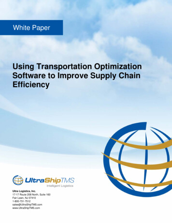
Baja SAE 2016-2017Background ResearchVehicle SubsystemsBefore engaging into modifying any of the components of the vehicle, the team needed tobecome familiar with all the parts that compose a vehicle. A diagram was created which shows allthe subsystems of the Baja vehicle. These systems include the steering, suspension, brakes, engine,drivetrain, and frame. See Appendix A.FrameWhen designing the frame, the SAE Rules require that minimum diameter and thicknesstubes are used for both the primary and secondary members of the frame. Both types of tube mustbe at least one inch in diameter. Primary members are the major structural members and had to beat least 3mm. They are denoted by the red members in Figure 1. The secondary members must beat least 0.089mm and are denoted in Figure 1 by all colors but red. All the tubes must also be madeof steel with at least 18% carbon. Previous MQP groups have used AISI 4130 Steel, also knownas chromoly steel. It has a carbon content anywhere from 28%-33%. It also has a high Young'sModulus at 460.0 MN/m2, so the material would be very strong and could take a lot of force beforeit begins to deform.Page 9 of 125
Baja SAE 2016-2017Figure 1 Primary and Secondary Member ClassificationSuspensionSuspension is defined as a system of tires, tire air, springs, shock absorbers, and linkagesthat connects a vehicle to its wheels and allows relative motion between the two [3]. Thesuspension system of a vehicle provides shock absorption. It dampens and absorbs the verticalforces that a vehicle might run into [4]. It also maintains contact between the tire and the drivingsurface [5]. If a vehicle does not have a suspension system, then an upward force could lift the tireoff of the ground if it were to come in contact with an obstacle in the road. The suspension systemwould allow tires to move up or down with a road surface while maintaining the frame height [5].There are generally different suspension types used for the front and rear of a vehicle. Since thefront and rear are two independent systems —two wheels connected by the front axle and twowheels connected by the rear axle— it is common to have a different type of suspension on thefront and rear. This is greatly determined by whether a rigid axle binds the wheels (dependentsystem) or if the wheels are permitted to move independently (independent system) [6]. Dependentfront suspensions are more common on trucks and have not been used on mainstream cars foryears [6]. The MacPherson strut, developed by Earle S. MacPherson of General Motors in 1947,is the most widely used independent front suspension system, especially in cars of European originPage 10 of 125
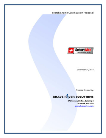
Baja SAE 2016-2017[6]. The MacPherson strut combines a shock absorber and a coil spring into a single unit. Thisprovides a more compact and lighter suspension system. Another common type of independentsystem is the double-wishbone, also known as double A-arm, suspension. Double-wishbonesuspensions allow for more control over the camber angle of the wheel, which describes the degreeto which the wheels tilt in and out. They also help minimize roll or sway and provide for a moreconsistent steering feel. Because of these characteristics, the double-wishbone suspension iscommon on the front wheels of larger cars.Shock AbsorberThe two main types of force dampening used in suspension systems are 1) the use ofsprings, and 2) the use of oil and nitrogen. Examples of springs used in force dampening includecoil-over springs, leaf springs, and torsion bars combined with a piston to provide fluid frictiondampening. Examples of oil and nitrogen used in force dampening includes various valvescontained in fluid shock [4]. Both of these force dampening types use the concepts of compressionand decompression. A coil over shock is shown in Figure 2 and an air shock is shown in.Figure 2 Coil Over Shock AbsorberPage 11 of 125
Baja SAE 2016-2017Figure 3 Air Shock AbsorberWheel AlignmentWhen designing a suspension, it is very important to consider certain parameters that willgreatly affect the wheel path of a vehicle. Those are: camber, caster, toe, and steering axisinclination (SAI). A correct alignment of these parameters will make the tires roll without scuffing,slipping, or dragging under all operating conditions.CamberCamber is defined as the inward or outward tilt of the wheel at the top relative to the verticalat the centerline of the wheel in the lateral plane. If the top of the tire is leaning inward toward thecenter of the car, the wheel has a negative camber. Inversely, if the top of the tire is leaningoutward, then the wheel has a positive camber. This can be visually conceptualized in Figure 4 [7].Camber, at a high angle, will wear the inside or outside tread of the tire. In terms of design, camberis changed by moving the control arm in or out without moving the ball joint.Page 12 of 125
Baja SAE 2016-2017Figure 4 Camber angleCasterCaster is the inclination of the steering axis Figure 5. Positive caster is achieved when thesteering axis is inclined towards the rear of the vehicle. Inversely, negative camber is when thesteering axis is inclined towards the front of the vehicle. Negative caster is rare, only used in heavyduty applications, as the wheel tends to swivel and follow the imperfections of the road. Positivecaster is common as it provides greater road feel and helps steering wheel returnability and stability[8]. In terms of design, caster is adjusted by moving the control arm so that the ball joint movestoward the front or rear of the vehicle.Page 13 of 125
Baja SAE 2016-2017Figure 5 CasterToeToe is determined by the difference in the distance between the front and rear of the leftand right-hand wheels [8]. Toe controls whether the wheels roll in the direction of steering ortravel. Toe-out is when the wheels are farther apart at the front than in the rear. Inversely, toe-in iswhen the wheels are closer at the front than at the rear (see Figure 6). Toe-in can give greaterstraight-line stability but will reduce the turning response and increase tire wear. Generally, frontwheels propel the vehicle, since they tend to push forward due to the engine torque. This pushcauses the wheels to point inward (toe-in) hence, to compensate this, the wheels are usually set tohave a toe-out at the front (approximately 1/16” or -5 degrees) [8]. Additionally, toe-out is a staticalignment made to minimize tire scrub and rolling resistance, which develop when a vehicle iscornering. In terms of design, toe is adjusted by lengthening or shortening the tie-rods.Page 14 of 125
Baja SAE 2016-2017Figure 6 Toe configuration (as viewed from the top)Steering Axis Inclination (SAI) or King Pin Inclination (KPI)The steering axis is the axis around which the wheel assembly swivels as it turns to theright or left. It is formed by drawing a line through the upper and lower ball joint pivots. SteeringAxis Inclination (SAI) is the angle in degrees between the steering axis and the vertical, as it canbe seen in Figure 7. SAI causes both front wheels to gain positive camber as they steer away fromcenter [9]—small amount but not to be neglected, especially for a vehicle making tight high speedturns such as the Baja. This acts with caster to provide self-centering of the front wheels. Thisgives the car straight line stability. SAI is usually kept below 8 since too much SAI causes a lotof rising of the front axle when steering [9].Page 15 of 125
Baja SAE 2016-2017Figure 7 SAI / KPIAnother important parameter, within steering, is the scrub radius (also seen in Figure 7).Scrub or pivot angle radius is the distance at the road surface between the steering axis line andthe centerline of the wheel, where the tread contacts the road. If these lines intersect at the roadsurface, a zero scrub radius would be present. When the intersection is below the surface of theroad, this is a positive scrub radius. Conversely, when the lines intersect above the road, negativescrub radius is present. This distance must be exactly the same from side to side or the vehicle willpull strongly [ ]. In terms of design, the scrub radius is changed whenever there is a change inwheel offset. For example, when the wheels are pushed out from the body of the vehicle the scrubradius becomes more positive. Ideally, on the front suspension, a small positive scrub radius givesstability because it causes toe out when braking and toe in when accelerating, in addition to easiersteering. A negative scrub radius is suitable for vehicles with high power engine [http://www.car-Page 16 of 125
Baja SAE s-and-effects-on-vehicle-behavior/]. In this case, forthe Baja vehicle, a small positive scrub radius is ideal as it is powered by a small engine. Thegreater the scrub radius (positive or negative), the greater the steering effort and the more roadshock and pivot binding that takes place. If the scrub radius is exactly zero, this causes scrubbingaction in opposite directions when the wheels are turned, thus tire wear and some instability incorners is the result.Page 17 of 125
Baja SAE 2016-2017Methods and ProcedureDesign SpecificationsThe following specifications were established with the intention of optimizing the SAE Bajavehicle and ensuring compliance of the Baja SAE competition requirements as regulated in theSAE International 2017 Collegiate Design Series Baja SAE Rules.Vehicle performance specifications: Must be able to withstand all obstructions or a combination of any:oRocksoSand jumpsoLogsoSteep inclines, climb hills of 40 degreesoMudoShallow water, showersoWeather: rain, snow, and ice Able to fall from a 15 ft jump and not break Able to reverse Adequate ground clearance and traction Contain four or more wheels not in a straight line Overall size oLess than 108 in. (274 cm) longoLess than 64 in. (162 cm) wideLimit weight of vehicle without person to approx. 400-450 lbsPage 18 of 125
Baja SAE 2016-2017 Hold a person of specific size - 95th percentile male / 5th percentile female:Table 2 Male/Female Driver ParametersParametersMaleFemaleWeight102kg/ 225lb49kg/ 108lbStanding height186.5cm/ 73.4in.151cm/ 59.6in.Hip height100.0cm/39.4in.74cm/29.1in.Erect sitting height97.0cm/38.2in.79.5cm/31.3in.Sitting shoulder height64.5cm/25.4in.50.5cm/19.9in.Sitting shoulder width50.5cm/91.9in37.5cm/14.8in.Hip width40.5cm/15.9in.31.0cm/12.2in.Shoulder grip length71.5cm/28.1in.55.5cm/21.9in.Foot length - bare28.5cm/11.2in22.0cm/8.7in.Foot width - bare11.0cm/4.3in.8.5cm/3.3in.o3in. Buffer space for 95th percentile male bodyo6in. Buffer space for 95th percentile male head/helmetDesign AnalysisSuspension SystemFormer MQP teams recommended that this MQP team optimize both the front and rearsuspension. After reading the former MQP team's recommendations, this MQP decided tocompletely redesign both the front and rear suspension. Research into suspension systemsindicated that it would be beneficial for competition to have a double A-arm for the frontsuspension and a single semi-trailing A-arm for the rear suspension. An example of a double APage 19 of 125
Baja SAE 2016-2017arm used in the front suspension is shown by RIT’s Baja vehicle in Figure 8.Looking at previous MQP data, it was determined that the vehicle would weigh roughly600 lbs fully loaded. The team assumed a 40% weight distribution in the front and 60% weightdistribution in the rear. This led to approximately 240 lbs and 360 lbs in the front and rear,respectively. [4] Based on the criteria, it was decided that the best option was the coil over shocks.When discussing the suspension with members of the Formula SAE MQP, the teamdecided on welding the tabs and suspension with weld cups to include spherical joints. Sphericaljoints will allow for angular rotation in two directions about the central point. This will beadvantageous to withstand obstacles during competition.Figure 8 RIT’s 2016 Vehicle Showing Double A-Arm in the Front SuspensionWe are ideally designing the suspension with front control arms with a length of 0.254 m(10 in.). The ideal rear control arms will be a little longer than the front control arms because ofthe fact that they will be trailing.Page 20 of 125
Baja SAE 2016-2017Figure 9 Front suspension designFront Suspension DesignRear Suspension DesignThe rear suspension was designed by using the recommendations from previous MQPteams and researching what other SAE Baja teams are currently designing for their rear suspensionsystem. The single semi-trailing A-arm proved to be the collective design option for the rearsuspension system. In designing the back of the vehicle, the team determined there was 14 incheson each side of the back of the vehicle that the suspension could extend outwards. The teamdetermined the correct geometry for the semi-trailing A-arm in SolidWorks. The team’s rearsuspension design is shown in Figure 10.Page 21 of 125
Baja SAE 2016-2017Figure 10 Rear Suspension DesignSteeringIn talking with members of the SAE club and observing the previous Baja vehicle, it wasdecided that the tie rods should be as perpendicular to the side of the vehicle as possible. Theyshould be angled just slightly down and back to give it negative caster, which will make it lessdifficult for the driver to steer the vehicle.TransmissionTorque GoalHill climb is one of the highly expected obstacles during competition. The Baja vehiclewill be expected to go over an incline of significant difficulty. The team assumed the incline to beapproximately 40 degrees. Through the inspection of previous courses, the group felt this wouldbe the maximum angle in any hill climb that the team might encounter. In order to successfully goPage 22 of 125
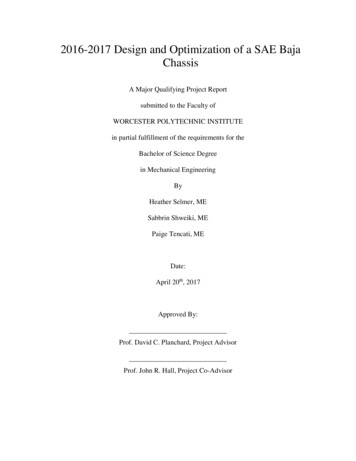
Baja SAE 2016-2017over the incline, the force on the two wheels will need to be greater than the force of gravity alongthe incline and the torque needs to be taken into account:Taking the body and wheels as a whole system:FN1 FN2WG2FfG1FN1FN2 Figure 11 Free Body Diagram of Baja for Hill Climb Event𝑚W 272kg (9.81 𝑠2 ) 2.668 kNgx Ff W · sin 2.668 𝑘𝑁 · 𝑠𝑖𝑛(40) 1.715 kNForce per wheel 𝑔𝑥2 1.715 𝑘𝑁2 0.858 kNAssuming a 23 in. diameter wheel:Torque per wheel:Equation 1 TorquePage 23 of 125
Baja SAE 2016-2017Twheel
Previous 2015-2016 SAE Baja MQP members. They particularly helped with the transfer of knowledge, which allowed for a smooth transition into the project. Bertan Atamer, team member of the 2013-2014 SAE Baja MQP Zachary Sears and James Waldo, team