Transcription
Innovative fine particulate measurement systems for the Wood StoveDesign ChallengeR. Trojanowski1, T. Butcher1, C. Brown1, G. Wei1, Y. Ahn2 , and J. Wong21.Energy Conversion Group, Brookhaven National Laboratory, Upton, New York, USAChemical and Molecular Engineering Department, Stony Brook University, Stony Brook, New York,USA2.ABSTRACTThe rising price of fossil resources has contributed to the increase in the amount of wood-firedresidential heating appliances. Wood stoves are often overlooked by the public as a clean andrenewable source due to concerns about particulate (PM) emissions. In order to gain acceptancein the market the Alliance for Green Heat and Popular Mechanics magazine initiated a WoodStove Design Challenge (WSDC). The selected teams designed stoves that incorporated the bestpractices in design and operation to maximize efficiency and minimize PM and carbon monoxide(CO) emissions since most often high emissions are seen as a result of incomplete combustion.Further, a testing protocol for the challenge was developed specifically to measure the emissionsin a non-laboratory setting. Standard testing procedures may not be representative of in-use fueland operational practices and, due to the competition venue and schedule contstraints, could notbe used for the WSDC. New portable PM sampling technology released in the European marketrecently was adopted for the competition and evaluated to current U.S. PM measurementmethods to build a correlation.INTRODUCTIONAs the price of heating oil has increased, more residents in the northeastern region of the UnitedStates have returned to heating with wood. Most existing wood stoves date from before theEnvironmental Protection Agency (EPA) implemented emission certification requirements forthese devices. These less efficient wood stoves often cause high amounts of smoke, yieldingparticulates known to trigger coughs, throat and mucosal irritation, acute respiratory infections,occurrence of asthma and other diseases over prolonged exposure1. A review from Bølling et al.reported residential wood combustion has also been reported to contribute significantly to raisedlevels of air pollution locally, both with respect to increased levels of fine particles (particulatematter with an equivalent aerodynamic diameter 2.5 µm; PM2.5), the organic particle fraction,particle bound polycyclic aromatic hydrocarbons (PAH) and volatile organic compounds2. Eventhose wood stoves that do meet EPA’s Phase II requirements may have unacceptably highemissions once in use. This is due to several factors including the design of the appliance,1Riddervold et al., “Effects of wood smoke particles from wood-burning stoves on the respiratory health of atopichumans”, Particle and Fibre Toxicology., 9:12, 2012.2Bølling et al., “Health effects of residential wood smoke particles: the importance of combustion conditions andphysicochemical particle properties”, Particle and Fibre Toxicology., 6:9, 2009.
weather patterns and location, combustion activity, wood species and quality, and operatorhabits. While the EPA is developing new regulations, the test method used for certification is notrepresentative of in-use fueling and operational practices.Designs that improve combustion and emission performance, thermal efficiency, and operationalvariability are needed in the U.S. heating market. Modern wood stoves have shown reducedreported emission factors compared to conventional wood stoves, 34-330 mg/MJ from 50-2100mg/MJ, respectively3. However, if the modern stoves are not operated correctly the combustionperformance can be compromised yielding higher emissions. The Alliance for Green Heat andPopular Mechanics Magazine initiated the Wood Stove Design Challenge (WSDC), aninternational competition modeled after the Department of Energy’s (DOE) Solar Decathlon, toaddress these needs by developing a competition for manufacturers, innovators, and universityteams. The WSDC challenged teams to design and build wood stoves that were low-emission,high efficiency, extremely innovative, affordable and marketable.This event showcased advanced technologies that could help address the problem of increasedparticulate emissions and enable the continued use of wood as a renewable fuel. The teamsselected came from various backgrounds, ranging from established wood stove companies toindependent inventors and engineering student teams. Some of the stoves selected for the WSDCwere controlled by microprocessors and connected to smartphones while others were ultraefficient stoves based on 17th century Scandinavian designs. Several state-of-the-art hybridstoves that are already on the market were also included 4. Six of the 12 finalists were fromEurope.Teams were judged on their innovation, emission and efficiency performance, affordability andconsumer ease. In November 2013 on the National Mall in Washington D.C., ten judges (madeup of leading experts from Popular Mechanics, the New York State Energy and ResearchDevelopment Authority (NYSERDA), the U.S. Forest Service, Washington State Department ofEcology, DOE’s Brookhaven National Laboratory (BNL), The Biomass Thermal Energy Council(BTEC), the Osprey Foundation, the Masonry Heater Association and UC Berkeley) tested andassessed the 12 stove finalists and announced an overall winner as well as winners in specificcategories.A key challenge in this competition was measuring the particulate emissions accurately in a fieldenvironment. This project sought to develop an energy efficiency and emissions testing protocolfor the WSDC which reduces the variability due to fuel and operations. The current standard testmethod (EPA Method 28) involves testing stoves using a dilution tunnel. Since the WSDC washeld at the mall in Washington D.C., this test method would not suit and so there was the3Bølling et al., “Health effects of residential wood smoke particles: the importance of combustion conditions andphysicochemical particle properties”, Particle and Fibre Toxicology., 6:9, 2009.4Bollman, Melissa., “Finalists Announced for International Competition to Build Cleaner Wood Stove”, Alliance forGreen Heat., January 2013. Web.
challenge of measuring the emissions in a repeatable real-time way, in a non-laboratoryenvironment. Recently, new portable particulate measurement systems have been introduced inEurope for field inspection of biomass heating systems. Two specific products were selected foruse in this project the Testo 380 and Wöhler SM 500. Both analyzers are a low cost option andoffer the advantage of ease and portability.To determine the accuracy, precision, instrument range, and applicability for use in the WSDCfor thermal efficiency and emissions of these portable direct measure analyzers, an evaluationwas conducted while simultaneously following the standard methods for determining theemissions. From laboratory testing, BNL developed a testing protocol implementing theanalyzers for the competition.INSTRUMENTSThe technology of the portable PM measurement systems includes near real-time, sub-miligramsensitivity, and is the only mass monitoring technology which has these properties and does notdepend on surrogate measurements for mass5. Each system utilizes the principles of oscillatingmicrobalances, using an inertial mass weighing principle. To begin, the system oscillates at itsnatural frequency exactly; as an air stream is drawn through the system, particles deposit on afilter or plate resulting in a loss of frequency oscillation. By measuring the change in frequency,the total mass of the particulate matter collected is found. Combining this number with thevolume of air drawn through the system provides the particle mass concentration (mg/m3). Thechange in mass may be determined from the following equation:()Where, Δm change in mass of particulates, fi initial oscillation frequency, ff oscillationfrequency after the collection of particulates, K0 system constant of the oscillator system, Kcor error correction function, and T temperature of the oscillator system.Both systems measure the PM in flue gas, O2, CO, draft, and stack temperature. One of thesystems uses a filter for particulate collection. The other uses an inertial impaction techniqueand, in this case, a correlation correction for the expected low collection efficiency of the veryfine particles is also used. Both systems report live measurements with a resolution down to 0.1mg.5H. Patashnick, M. Meyer, and B. Rogers., “Tapered element oscillating microbalance technology”., Proceedings ofthe North American/Ninth U.S. Mine Ventilation Symposium, p. 625-631., Kingston, Ontario, Canada., 8-12. June2002.
TRADITIONAL TEST METHODSThe current standard test procedure for wood stoves (EPA Method 28) provides a fueling andoperating procedure for wood heater emission and efficiency testing. Fuel properties, loadconfiguration, pre-test conditions, charcoal bed, loading and start-up time, allowable air supply,fuel adjustments, and other parameters are all specified by Method 28 in order to provide astandardized test for stove certification. Particulates are measured using a dilution tunnelapproach. Method 28 uses various measurement procedures to collect the particulate matter.These methods include 5H, G-1, 5G-2, and 5G-3. For the purpose of this study only EPAMethod 5G-3 will be discussed in detail.
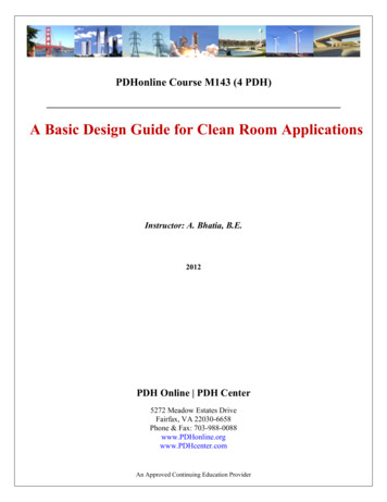
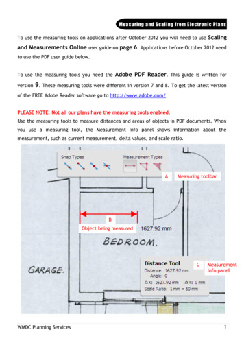
LABORATORY SET UPTo provide a basis for comparison, the traditional sampling method along with the portableanalyzers were operated in side-by-side laboratory tests over various phases of a wood stoveburn cycle. Traditional test methods require crib wood fuel (dimensional lumber; 2 X 4’s) as anattempt to maximize the consistency and reproducibility from test to test. However, cord woodwas used as it was more representative of field use and practices to follow in the WSDC. AnEPA certified wood stove (Woodstock Soapstone Co. Fireview model) was provided for thisproject. The standard catalytic stove had a maximum output 55,000 Btu/hr with a manual draftcontrol.The traditional EPA Method 5G-3 was used as the sampling procedure for capturing particulates.This filter-based, time-integrated system involved two 47 mm filters in series and sampled froma dilution tunnel which collected all the effluent from the stove’s chimney and drew it, withambient dilution air, through a straight duct at a constant velocity (measured with a pitot tubeand digital pressure gauge). The sampled air stream was monitored to maintain a constant flowrate as it was pulled through the filter media, depositing the PM on the filter. The filters werepre- and post-desiccated, following Method 5G-3 to remove all moisture and assure the changein weight was only associated with the particulates collected. With a known volume of air passedthrough the filter media and weight change, the particle mass concentration (mg/m3) wasdetermined. Following method 5G-3, it is required that two identical sampling trains be usedsimultaneously and the results from each train agreed with each other within 7.5% of the mean inorder to validate the results. The laboratory experimental set-up may be seen in Figure 1.Gaseous emissions (CO and O2) were also measured from the dilution tunnel continuously overthe full combustion period. Carbon monoxide was measured in the dilution tunnel using aRosemount Analytical model 880 non-dispersive infrared sensor (NDIR) CO analyzer. Theanalyzer has a maximum capacity of 5000 ppm, therefore any data above that goes unmeasured.Oxygen measured in the dilution tunnel used a Beckman model 755 oxygen analyzer.Temperature data was also collected using thermocouples, situated at precise locations, loggedon a continuous basis over the burn period.
Figure 1: Laboratory set-upBoth of the portable PM analyzers sampled particulate concentration, CO and O2 concurrentlywith the traditional test method. However, a disadvantage seen with the portable analyzers isthat they are intended and designed for sampling directly from the stack and not from a dilutiondevice. As a result of this, and the temperature of the instrument’s head of the sampling probe,the semivolatile (condensable) hydrocarbons are not fully captured and therefore the yieldedmeasurements are not expected to be the same as the dilution tunnel-based method. Bothanalyzers were situated in the stack perpendicular to each other.Aside from the scope of this project but used for additional data, in some tests, was an opticalPM measurement. The Thermo pDR-1500 is designed to measure the concentration of PM usinga light-scattering photometer (nephelometer). The intensity of the light scattered is proportionalto the concentration of particles passing through the sensors. The Thermo pDR-1500, similar tothe Testo and Wöhler, is a real time PM monitor. Humidity, temperature, and pressure are somefactors that may affect emission measures; the pDR compensates for these factors and allows fora nominal accuracy to within 5% of the reading6. The pDR sampled in the dilution tunnel.RESULTS AND DISCUSSIONTesting the portable analyzers against laboratory-based test methods and in some cases opticalmeasurements demonstrated the analyzers abilities to produce repeatable, accurate results sincethere was no opportunity to test each stove to the traditional standard protocols.All measurement processes have an inherent element of variability of result if the process hassufficiently fine resolution7. In combustion systems especially, it is expected to obtain a widerdispersion of results for the experiment if it is repeated under a wide range of ambient67Thermo Fisher Scientific., “pDR-1500”, 00.htmlCurkeet, Rick and Ferguson, Robert., “EPA Wood Heater Test Method Variability Study”., October 2010.
conditions, such as different temperature, wind, and or humidity condition. EPA’s Method 28has a tremendous amount of variability, which is not unique to only this method. Curkeet andFerguson8 [7] summarized the sources of variability which include: Fuel density variation from approximately 30 to 40 lb/ft3 (dry weight basis).Fuel moisture content variation from 19 to 25% dry basis (varies in uniformity as well asaverage).Fuel load configuration details.Coal bed size (20-25% of fuel load weight) and pre-burn temperature conditions.Loading time and start-up procedure.Ambient temperature, barometric pressure and humidity.Variations in control settings and resulting burn rates.Random uncontrollable variables such as when and how the fuel load settles, falls andcollapses.Most notably is the impact these factors have on the appliances’ burn rate, which to some degreeis related to the emissions performance. With higher burn rates generally producing morecomplete combustion emissions are ultimately lowered. It is important to note Method 28 strivesto reduce the variability within the test method by placing tolerances on the operational andfueling parameters however, variability still exists.Operating protocols themselves are not the only source of variability; other variability comesfrom the sampling methods themselves. The variability in Method 5G-3 PM measurements existsin the accuracy of the dilution tunnel gas flow and sample flow measurement and the resultingconsistency of proportionality. Weighting errors for weights of filters, probes including frontfilter housings and filter seals also exist. The measurement uncertainty of method 5G-3 has beendetermined to be approximately /- 2.5% of the emission value measured for a typical passingwood stove test8. Method 5G-3 was chosen as it demonstrates the lowest uncertainty of the fourmethods.There is also variability associated with portable analyzers. Each analyzer builds in anuncertainty value that accounts for the uncertainty of the fueling protocol, stove operation, andmeasurement. This is the value used for certification in Germany; however numbers recorded forthis report were the actual yielded values. In Europe, these analyzers are used to demonstrate thata field installation is operating with PM emissions below a set level (expressed simply asmg/m3). The measured values are corrected for the uncertainty to evaluate compliance. Theuncertainty assigned, for these analyzers, is rather large, 30-50%.As the dilution tunnel mixes exhaust gases with ambient air, and sampling was done in both thestack and dilution tunnel, a dilution ratio must be calculated and applied to the filter-based andpDR methods in order to compare the each method to the next. To determine a dilution ratio, a8Curkeet, Rick and Ferguson, Robert., “EPA Wood Heater Test Method Variability Study”., October 2010.
heat balance approach was used. A correlation between CO values of the portable analyzers tothe NDIR analyzer in the dilution tunnel was attempted, but was unsuccessful. The followingcalculations show the steps taken to determine a dilution ratio based on temperature.̇̇̇Where subscripts A, R, S, and DT are ambient, reference, stack and dilution tunnel, nowing the temperatures of the room, dilution tunnel and stack (at the top, right beforedilution), the dilution ratio can be calculated. In all cases, the dilution ratio was approximately7.25 during the stoves operation. Knowing this value, the PM concentration determined by thefilter-based method and the pDR was multiplied by 7.25 in order to more accurately compare thePM concentrations captured by the portable analyzers sampling in the stack.The results from three different days and six different tests are shown below. Tests 1 and 2 wererun back to back on the given day. The fueling protocol followed for the November 11th testinvolved a pre-burn to establish a coal bed (described in detail below). Once the coal bed wasestablished, a fuel charge of 11 lb/ft3 was added (roughly 24lbs for this particular stove). The fuelwas red oak (for laboratory experiments only) and had an average moisture content of 20%.Thirty minutes after the addition of this fuel charge, the first steady state burn period was
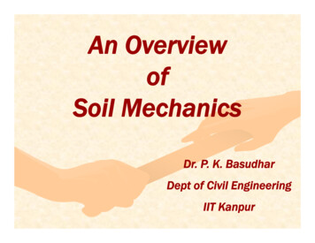
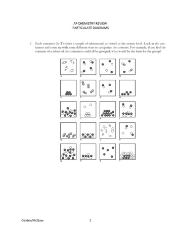
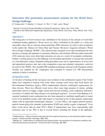
established (Test 1). Sampling for both Tests 1 and 2 had a duration of 15 minutes. After Test 1’s15 minute sampling period was complete, the fuel charge was left to burn out. Once the coal bedwas re-established (20% of the fuel charges weight), a second full fuel charge was addedsignifying Test 2. Again, after 30 minutes of the fuel charge addition, sampling begun for Test 2.For both tests, the catalyst was engaged and the air damper was set at position two of four.The formal operational procedure was only followed for the first day; however it was notnecessary for the comparison of sampling instruments. Therefore, the latter two days followedmuch less formal fueling procedures. What was most important was all sampling procedureswere followed (i.e. Method 5G-3) and all sampling methods were captured simultaneously. Tests1 and 2 from the December 16th and 17th were still run back to back but this time sampled fromone fuel charge only (approximately 24lbs of fuel) throughout the course of the burn. Therefore,these 15 minute tests captured a mix of steady state periods and end of burn periods- a cleanertime period. From the results it can be seen traditional test methods in the dilution tunnel (withthe applied dilution ratio) yielded different results than those of the portable analyzers, asexpected, but not to a large degree. PM emissions comparisons are provided in Figures 2, 3, and4. In these figures Train 1 and Train 2 refer to the direct mass measurement using Method 5G-3.PM (mg/m3)200150100500pDRTrain 1Train 2Analyzer 1Analyzer 2Test 2pDR24.7Train 169.6Train 274.0Analyzer 180.5Analyzer 2126.0Test 1127.6193.6195.0196.3172.0Test 2Test 1Figure 2: PM concentration on 11/11/2013
PM (mg/m3)200150100500Train 1Train 2Analyzer 1Analyzer 2Test 2Train 157.6Train 252.4Analyzer 120.6Analyzer 24.0Test 1177.3187.4121.4127.0Test 2Test 1Figure 3: PM concentration on 12/16/2013250PM (mg/m3)200150100500Train 1Train 2Analyzer 1Analyzer 2Test 1Train 1210.1Train 2184.0Analyzer 1161.6Analyzer 2201.0Test 2168.4176.0240.6245.0Test 1Test 2Figure 4: PM concentration on 12/17/2013
Dilution sampling better represents what is emitted into the environment and allows morevariables to be measured. The dilution tunnel mixes the stack effluent with clean ambient air,simulating what happens in the plume as emissions exit the appliance’s chimney. Sampling viathe dilution tunnel captures particulate matter (elements, ions, organic and elemental carbon),semi-volatile organic compounds (SVOCs), and volatile organic compounds (VOCs). Thedilution tunnel should capture all of the filterable matter plus any aerosols that condense undersimulated plume conditions9. This may in turn be the reason for the higher PM concentrationscaptured via Method 5G-3.Another thought is the portable analyzers heat their probes and sampling lines to either 80 C or120 C and are modeled after European test methods such as EN 303-5. Method EN 303-5samples directly in the stack, maintains the filters temperature at an elevated temperature duringsampling, and bakes the filter both pre and post test. Previous studies at BNL comparing EN303-5 to EPA’s Method 28 indicated differences in PM concentration between the two. This toorelates back to the fact of lower temperatures in the dilution tunnel lead to capturing thecondensable particles missed in the hot stack. Another disadvantage seen in test 2 of December16th, 2013 was analyzer 2 actually lost weight as the sampling period went on. This may due towater interference and this test should be considered invalid.The pDR was eliminated after the first day of testing due to its results. The pDR is a useful toolto get an idea of the amount of particulates and has the ability to capture very high PMconcentrations such as start up unlike other sampling tools. However, the pDR’s accuracyseemed to degrade as the burn got cleaner; when the particle size distribution was very small.Application to the WSDC in D.C.As the objective was not to certify each unit, but evaluate each stove in terms of its emission andefficiency performance relative to the other stoves in the competition, results from the portableanalyzers prior to DC were promising. The competition’s venue and time did not allow for adilution tunnel to be constructed and scale under each stove, therefore traditional test methodswere not an option. Data collected from the portable analyzers was repeatable and comparable toone another. Results from prior testing illustrated the analyzers were able to sample directly fromthe stack and offer good comparative numbers to those attained by traditional test methods. Fromthe testing done at BNL prior to the competition, a test procedure was established which servedas a fair basis to compare each stove in terms of its emissions and efficiency during operation.Twelve stoves competed in the WSDC, each unique to the next. The stoves varied in terms ofmaterials, combustion chamber designs, and controls. Two of the five categories judged included9Wien, S., England, G. C., Loos, K., Ritter, K., Gurney, D., McCarthy, J., Liebowitz, B., Joseph, J. and Franco, G. 2001.PM2.5 Speciation Profiles and Emission Factors From Petroleum Industry Gas-Fired Sources. ProceedingsInternational Emission Inventory Conference, “One atmosphere, One inventory, Many challenges.”. May1–32001,Denver, CO.
efficiency and emissions (made up of carbon monoxide and PM). These values were provided bythe portable analyzers. To ensure fair and representative data, each stove was tested two times(once which each analyzer) over the course of the competition and during the same part of theburn.Fueling protocolThe fueling protocol was created by Ben Myren of Myren Consulting. Ben has years ofexperience in wood burning as Myren Laboratories serves as one of the few EPA certificationlaboratories. The fueling protocol involved a pre-burn to establish a coal bed. This pre burnincluded kindling and two ricks (small bundles of wood), each with a specified amount based onthe stove’s firebox dimensions. Once the coal bed was established, a fuel charge of 11 lb/ft3 wasadded. The fuel was a mixed species and average moisture content of 20%. To reduce thevariability of the fueling protocol from stove to stove, each piece of fuel has to meet the criteriaestablished; weight and moisture content from the moisture meter was all recorded.After the first day of testing it was noted the 11 lb/ft3 was too large of a loading for some stovescausing them to choke, and perform poorly and in a manner unrepresentative of field operation.Therefore, the second day of testing yielded a fueling proposal to stove manufactures’; as low as8 lbs/ft3 would be acceptable. Another adjustment made was to the masonry heaters in thecompetition. The masonry heaters did not have a pre-burn period and simply had the kindlingand fuel charge all in one load.Testing procedureA test protocol was developed at BNL prior to the competition which was repeatable,representative of the stove’s performance, and mindful of time. Due to time constraints eachstove was tested two times (once with each analyzer to account for any variability from analyzerto analyzer), both during the steady state burn cycle. The steady state burn period was chosen tostart after 30 minutes of the fuel charge addition. Based on European standards that the analyzersfollow, a 15 minute window was selected as the measurement time. Both analyzers did have thecapability of testing longer, e.g. 30 minutes if desired, however mindful of the time to clean andprep the analyzers and stoves between testing cemented the decision for a 15 minutemeasurement. Quality control measures were also taken to guarantee each test was executed tothe test method.After the first day or testing, it was noted the 30 minute start time after the fuel charge was addedwas not always the steady state period of the stove, therefore adjustments were made. Inaddition, smaller stoves and masonry heaters began testing after 15 minutes as their burns wereoften short and quick, achieving steady state sooner than 30 minutes.Initially desired was to test the stoves during their dirtiest burn phase, start up. However, tests atBNL prior to the competition, sampling during the start up period were problematic. Often theanalyzers overloaded with PM, generating errors and were unable to sample for the full 15
minutes. The data also showed poor repeatability and at times were ill-matched to each other.Having no emission data and little information on each stove prior, it was difficult to anticipate ifthe analyzers could sample start up for a minimum of 15 minutes and so, start up testing waseliminated. If time had permitted, those top competing stoves which had the lowest emissionswould have had the ability to be tested during their start up.RESULTSValues for the efficiency and emissions (made up of carbon monoxide and PM) categories wereprovided by the portable analyzers. The PM concentration in mg/m3 was generated directly bythe analyzers. Carbon monoxide emissions reported by the analyzers were corrected to 13%based on German standards (Austrian standards differ); therefore CO numbers had to be adjustedbefore reported. The calculation was as follows:()From the O2, temperature (stack and ambient), and CO values obtained, the stack loss efficiencyof each stove was determined. The efficiency calculation used for the competition was a stackloss method following CSA B415. The reported values were not an overall efficiency and areonly representative of the 15 minute window. The efficiency calculation also did not includejacket losses or wood consumption and only served as a comparative value from stove to stove inthe competition; outside the competition this value has little meaning.The stack loss efficiency calculation is an indirect efficiency test method and often used todetermine the efficiency of gas- and oil-fired appliances; however it can be related to solid-fuelsbut is more complicated. Since ample time did not exist and neither did a scale under each stoveat the competition, this method was used as an approximation. The stack loss efficiencycalculation took into account the sensible heat loss, latent heat loss and chemical heat loss. Thefuel composition in terms of carbon, hydrogen, and oxygen percentages, higher heating value,and moisture content is therefore needed. Ambient temperatures were also needed. Method 28and CSA B415.1 may be referenced for a more detailed explanation of the calculation. Asimplemented for the competition, the stack loss method considered the chemical energy in COemissions but did not consider the chemical energy in hydrocarbon emissions. This parameterwas simply not measured. For this reason the reported efficiencies may be slightly higher thanactual.It is well known burning wood is never steady and therefore measured values are constantlychanging but the 15 minute window sought to capture the most steady state so the efficiencycalculation could be compared to each of the stoves at the competition. The fact that theanalyzers were able to measure values every five seconds certainly helped to provide a moreaccurate result.
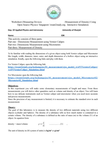
Figures 5 to 7 below depict the PM, CO and efficiency results from the WSDC. It is important tonote stoves were tested only once a day over the course of four days. Analyzers chosen for aparticular stove on a given day were unbiased; for example analyzer one was not run only on dayone and three while analyzer two was only run on days two and four.250PM (mg/m3)200150Analyzer 1100Analyzer 250012345678910StoveFigure 5: PM emissions of wood stoves at WSDC1112
3000025000CO (ppm)2000015000Analyzer 1Analyzer 21000050000123456789101112StoveFigure 6: CO emissions of wood stoves at WSDC80Efficiency7060ɳ (%)5040Analyzer 1Analyzer 23020100123456789101112StoveFigure 7: E
Designs that improve combustion and emission performance, thermal efficiency, and operational . (BTEC), the Osprey Foundation, the Masonry Heater Association and UC Berkeley) tested and assessed the 12 stove finalists and a