Transcription
Data Communications andNetworking byForouzan fourth editionChapter 12Multiple AccessMcGraw-Hill12.1 The McGraw-Hill Companies, Inc., 2000
Multiple AccessIn Chapter 11 we discussed data link control, a mechanismwhich provides a link with reliable communication. In theprotocols we described, we assumed that there is anavailable dedicated link (or channel) between the senderand the receiver. This assumption may or may not be true.If, indeed, we have a dedicated link, as when we connectto the Internet using PPP as the data link control protocol,then the assumption is true and we do not need anythingelse.PPP: point-to-point protocol(byte oriented ) which providesconnections over multiple links and has a very simplemechanism for error control. 12.2
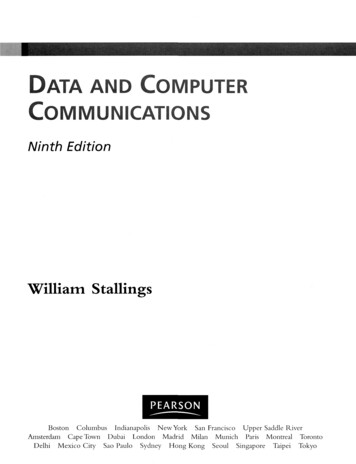
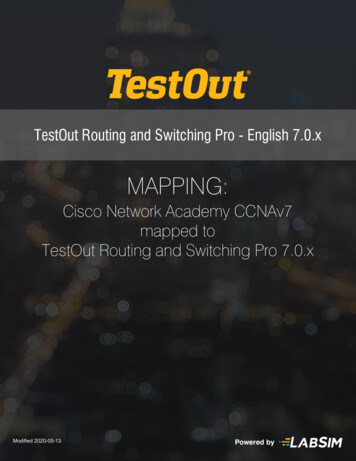
We can consider the data link layer as two sublayers. The upper sublayer is responsible for data link controland error control is called the logical link control (LLC)layer . The lower sublayer is responsible for resolving access tothe shared media is called the media access control(MAC) layer . If the channel is dedicated, we do notneed the lower sublayer. Figure 12.1 shows these two sublayers in the data linklayer. When nodes or stations are connected and use acommon link, called a multipoint or broadcast link, weneed a multiple-access protocol to coordinate access tothe link.12.3
Figure 12.1 Data link layer divided into two functionality-oriented sublayersUpper sublayer – responsible for data link control Called LLC – for flow and error controlLower sublayer - responsible for resolving access the shared media Called MAC – for multiple acceess resolution12.4
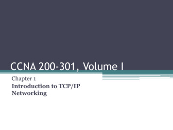
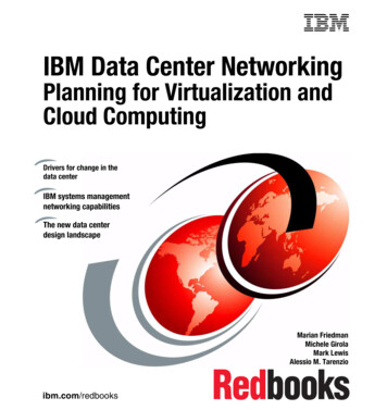
The problem of controlling the access to the mediumis similar to the rules of speaking in an assembly. Theprocedures guarantee that the right to speak is up heldand ensure that two people do not speak at the sametime, do not interrupt each other. The situation is similar for multipoint networks.Many formal protocols have been devised to handleaccess to a shared link. We categorize them into threegroups. Protocols belonging to each group are shownin Figure 12.2.12.5
Figure 12.2 Taxonomy of multiple-access protocols discussed in this chapter12.6
12-1 RANDOM ACCESSIn random access or contention methods, no stationis superior to another station and none is assignedthe control over another. No station permits, or doesnot permit, another station to send. At each instance,a station that has data to send uses a proceduredefined by the protocol to make a decision onwhether or not to send. The decision depends on thestate of the medium (idle or busy).Topics discussed in this section:ALOHACarrier Sense Multiple AccessCarrier Sense Multiple Access with Collision DetectionCarrier Sense Multiple Access with Collision Avoidance12.7
12.8Two features give this method its name. First, there is noscheduled time for a station to transmit. Transmission is randomamong the stations. That is why these methods are called randomaccess. Second, no rules specify which station should send next.Stations compete with one another to access the medium. That iswhy these methods are also called contention methods.In a random access method, each station has the right to themedium without being controlled by any other station. However,if more than one station tries to send, there is an access conflictcollision-and the frames will be either destroyed or modified.The random access methods we study a very interesting protocolknown as ALOHA, which used a very simple procedure calledmultiple access(MA), that forces the station to sense the mediumbefore transmitting.
ALOHA 12.9It was designed for a radio (wireless) LAN, but it can be used onany shared medium. The medium is shared between the stations.When a station sends data, another station may attempt to do soat the same time. The data from the two stations collide .The original ALOHA protocol is a simple, but elegant protocol.The idea is that each station sends a frame whenever it has aframe to send. Figure 12.3 shows an example of frame collisionsin pure ALOHA. Some of these frames collide becausemultiple frames are in contention for the shared channel.
Figure 12.3 Frames in a pure ALOHA networkPure ALOHA:1. Each station sends a frame whenever is has a frame to send2. One channel to share, possibility of collision between frames from different stations12.10
Figure 12.4 Procedure for pure ALOHA protocol12.11
Figure 12.5 Vulnerable time for pure ALOHA protocol12.12
Figure 12.6 Frames in a slotted ALOHA networkSlotted ALOHA:1. We divide the time into slots and force the station to send only at the beginning ofthe time slot12.13
Figure 12.7 Vulnerable time for slotted ALOHA protocol12.14
Carrier Sense Multiple Access (CSMA) 12.15To minimize the chance of collision and, therefore, increasethe performance, the CSMA method was developed. Thechance of collision can be reduced if a station senses themedium before trying to use it. CSMA requires that each stationfirst listen to the medium (or check the state of the medium)before sending. it is based on the principle "sense beforetransmit“.CSMA can reduce the possibility of collision, but it cannoteliminate it. The possibility of collision still exists because ofpropagation delay.
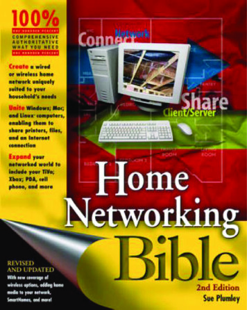
What should a station do if the channel is busy or idle? Three methodshave been devised are:I-Persistent The I-persistent method is simple and straightforward. Inthis method, after the station finds the line idle, it sends its frameimmediately (with probability I).This method has the highest chance of collision because two or morestations may find the line idle and send their frames immediately,Ethernet uses this method.Nonpersistent In the nonpersistent method, a station that has a frameto send senses the line. If the line is idle, it sends immediately. If theline is not idle, it waits a random amount of time and then senses theline again. The nonpersistent approach reduces the chance of collisionbecause it is unlikely that two or more stations will wait the sameamount of time and retry to send simultaneously. However, thismethod reduces the efficiency of the network because the mediumremains idle when there may be stations with frames to send.12.16
p-Persistent The p-persistent method is used if thechannel has time slots with a slot duration equal to orgreater than the maximum propagation time. The p-persistent approach combines the advantagesof the other two strategies. It reduces the chance ofcollision and improves efficiency.12.17
Figure 12.10 Behavior of three persistence methods1-Persistent-after stationfinds the line idle, sendits frameNonpersistent-senses theline; idle: sendsimmediately; not idle:waits random amount oftime and senses againp-Persistent-the channelhas time slots withduration equal to orgreater than maxpropagation time12.18
Figure 12.11 Flow diagram for three persistence methods12.19
Carrier Sense Multiple Access with CollisionDetection (CSMA/CD) 12.20In this method, a station monitors the mediumafter it sends a frame to see if the transmissionwas successful. If so, the station is finished. If,however, there is a collision, the frame is sentagain.
Example 12.5 (Minimum frame size)A network using CSMA/CD has a bandwidth of 10Mbps. If the maximum propagation time (including thedelays in the devices and ignoring the time needed tosend a jamming signal, as we see later) is 25.6 μs, whatis the minimum size of the frame?SolutionThe frame transmission time is Tfr 2 Tp 51.2 μs.This means, in the worst case, a station needs totransmit for a period of 51.2 μs to detect the collision.The minimum size of the frame is 10 Mbps 51.2 μs 512 bits or 64 bytes. This is actually the minimum sizeof the frame for Standard Ethernet.12.21
Figure 12.14 Flow diagram for the CSMA/CD (Page 375)12.22
12-2 CONTROLLED ACCESSIn controlled access, the stations consult one anotherto find which station has the right to send. A stationcannot send unless it has been authorized by otherstations. We discuss three popular controlled-accessmethods.Topics discussed in this section:ReservationPollingToken Passing12.23
Reservation In the registration method, a station needs to make aregistration before sending data. Time is divided into intervals. In each interval, areservation frame precedes the data frames sent inthat interval. Figure 12.18 shows a situation with five stations anda five-minislot reservation frame.12.24
Figure 12.18 Reservation access methodReservation-station needs to make a reservation before sending data12.25
polling 12.26Polling works with topologies in which one device isdesignated as a primary station and the other devices aresecondary stations. All data exchanges must be made throughthe primary device even when the ultimate destination is asecondary device.The primary device controls the link; the secondary devicesfollow its instructions. It is up to the primary device todetermine which device is allowed to use the channel at agiven time. The primary device, therefore, is always theinitiator of a session (see Figure 12-19).
Figure 12.19 Select and poll functions in polling access methodPolling – one device as primary station and the other device as secondary stationSelect – primary device wants to send data to secondary device, secondary devicegets ready to receivePoll – primary device solicits (ask) transmissions from secondary devices12.27
The poll function is used by the primary device to solicittransmissions from the secondary devices. When the primary isready to receive data, it must ask (poll) each device in turn if ithas anything to send. When the first secondary is approached, itresponds either with a NAK frame if it has nothing to send orwith data (in the form of a data frame) if it does. If the response is negative (a NAK frame), then the primarypolls the next secondary in the same manner until it finds onewith data to send. When the response is positive (a data frame),the primary reads the frame and returns an acknowledgment(ACK frame), verifying its receipt12.28
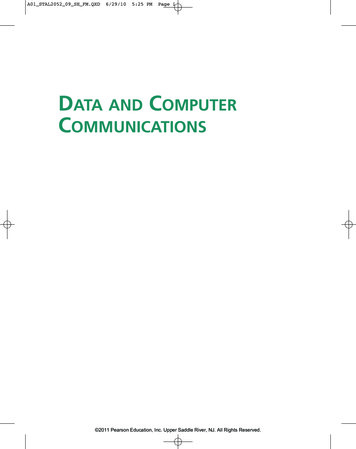
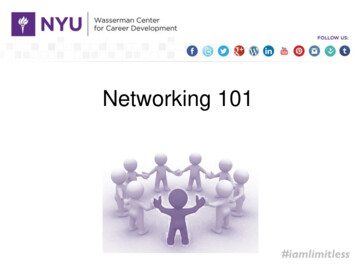
Token passing – stations in network organized in a logical ring –predecessor and successorToken – gives station right to access the channel; needs tokenmanagementPhysical ring – station sends the token to successorDual ring – uses second ring which operates in reverse directionBus ring (token bus) - stations are connected to single cable called bus,but make logical ringStar ring - physical topology star, wiring inside hub makes the ring12.29
Figure 12.20 Logical ring and physical topology in token-passing access method12.30
12-3 CHANNELIZATION (Beyond class scope)Channelization is a multiple-access method in whichthe available bandwidth of a link is shared in time,frequency, or through code, between differentstations.Examples of Channelization:Frequency-Division Multiple Access (FDMA)Time-Division Multiple Access (TDMA)Code-Division Multiple Access (CDMA)12.31
Frequency-Division Multiple Access (FDMA) 12.32In frequency-division multiple access (FDMA), the availablebandwidth is divided into frequency bands. Each station isallocated a band to send its data. In other words, each band isreserved for a specific station, and it belongs to the station allthe time.Each station also uses a bandpass filter to confine thetransmitter frequencies. To prevent station interferences, theallocated bands are separated from one another by small guardbands. FDMA, on the other hand, is an access method in thedata link layer. The data link layer in each station tells itsphysical layer to make a bandpass signal from the datapassed to it. The signal must be created in the allocated band.
Time-Division Multiple Access (TDMA) 12.33In time-division multiple access (TDMA), the stations sharethe bandwidth of the channel in time. Each station is allocateda time slot during which it can send data.Each station transmits its data in is assigned time slot.The main problem with TDMA lies in achievingsynchronization between the different stations. Each stationneeds to know the beginning of its slot and the location of itsslot.This may be difficult because of propagation delays introducedin the system if the stations are spread over a large area.
12.34In TDMA, the bandwidth is just onechannel that is timeshared betweendifferent stations.
Code-Division Multiple Access (CDMA) 12.35Code-division multiple access (CDMA) was conceived severaldecades ago. Recent advances in electronic technology havefinally made its implementation possible.CDMA differs from FDMA because only one channeloccupies the entire bandwidth of the link. It differs fromTDMA because all stations can send data simultaneously;there is no timesharing. CDMA simply means communicationwith different codes.For example, in a large room with many people, two people can talk inEnglish if nobody else understands English. Another two people can talk inChinese if they are the only ones who understand Chinese, and so on. Inother words, the common channel, the space of the room in this case, caneasily allow communication between several couples, but in differentlanguages (codes).
McGraw-Hill The McGraw-Hill Companies, Inc., 2000 Data Communications and Networking