Transcription
WORKING DRAWINGS HANDBOOK
This page intentionally left blank
WORKING DRAWINGSHANDBOOKFourth EditionKeith Styles and Andrew Bichard
Architectural PressAn imprint of ElsevierLinacre House, Jordan Hill, Oxford OX2 8DP30 Corporate Drive, Burlington, MA 01803First published 1982Second edition 1986Third edition 1995Reprinted 1998, 2000, 2002, 2003Fourth edition 2004Copyright 2004, Keith Styles and Andrew Bichard. All rights reservedThe right of Keith Styles and Andrew Bichard to be identified as the authors ofthis work has been asserted in accordance with the Copyright, Designs andPatents Act 1988No part of this publication may be reproduced in any material form (includingphotocopying or storing in any medium by electronic means and whetheror not transiently or incidentally to some other use of this publication) withoutthe written permission of the copyright holder except in accordance with theprovisions of the Copyright, Designs and Patents Act 1988 or under the terms ofa licence issued by the Copyright Licensing Agency Ltd, 90 Tottenham Court Road,London, England W1T 4LP. Applications for the copyright holder’s writtenpermission to reproduce any part of this publication should be addressedto the publisherPermissions may be sought directly from Elsevier’s Science & Technology RightsDepartment in Oxford, UK: phone: ( 44) 1865 843830, fax: ( 44) 1865 853333,e-mail: permissions@elsevier.co.uk. You may also complete your request on-line viathe Elsevier homepage (http://www.elsevier.com), by selecting ‘Customer Support’and then ‘Obtaining Permissions’British Library Cataloguing in Publication DataA catalogue record for this book is available from the British LibraryLibrary of Congress Cataloguing in Publication DataA catalogue record for this book is available from the Library of CongressISBN 0 7506 6372 3For information on all Architectural Press publicationsvisit our website at www.architecturalpress.comTypeset by Newgen Imaging Systems (P) Ltd., Chennai, IndiaPrinted and bound in Great Britain byBiddles Ltd, King's Lynn, NorfolkWorking together to growlibraries in developing countrieswww.elsevier.com www.bookaid.org www.sabre.org
ContentsIntroduction11 The structure of information22 The general arrangement drawing353 Component, sub-component and assembly drawings614 Drawing the set885 Working drawing management113Appendix 1 Building elements and external features145Appendix 2 Conventions for doors and windows148Appendix 3 Symbols indicating materials150Appendix 4 Electrical, telecommunications and fire protection symbols152Appendix 5 Non-active lines and symbols156Appendix 6 Glossary of CAD terms158Index161v
This page intentionally left blank
IntroductionThis book had its origins in the series of articles of theIt had been hoped at the outset to illustrate the book withsame name published in the Architects’ Journal in 1976actual drawings taken from live projects, but for variousand 1977. My thanks are due therefore to my fellowreasons this proved to be impracticable. Invariably thecontributors to that series, Patricia Tutt, Chris Daltryscale was wrong, or the drawing was too big, or was tooand David Crawshaw, for many stimulating discussionsprofusely covered with detail irrelevant to the immediateduring its production, and to the Architects’ Journal forpurpose. In the event the drawings in the book haveallowing me to reproduce material from it. The text ofbeen drawn for it especially, or have been redrawn for itthe first edition, however, was completely rewritten,from source material provided by others. My thanks forand responsibility for the views expressed andproviding such material are due to Messrs Oscar Garryrecommendations made therein were mineand Partners, the Department of Health and Socialalone.Security, Messrs Kenchington Little and Partners,Autodesk Ltd and the Property Services Agency. ThanksThe development of CAD since publication of theare also due to The British Standards Institution, Thethird edition has led to a major revision and up-datingRoyal Institute of British Architects, and the Constructionto include details of the application of the latestProject Information Committee for permission to useCAD techniques to the whole field of productionmaterial for which they hold the copyright.drawings. This has led to the introduction ascollaborator of Andrew Bichard, the well-knownA final caveat: the illustrations have been selected –architect and writer on CAD topics, who is anindeed, in many instances devised – solely for theiracknowledged leader in the field. He has written thefunction in illustrating points made in the text, and aresections on CAD, and in particular all the CADnot presented as working details to be used for anydrawings have been produced by him.other purpose.1
CHAPTERThe structure ofinformationNo one who has delivered drawings to site and overhead1 the foreman’s jocular reference to a ‘fresh set of comicshaving arrived’ will deny that the quality of architects’working drawings in general is capable of improvement.omissions—items of information accidentallymissing poor presentation—(i.e. the drawing or set ofdrawings was complete but confusing to read).In some measure we have all of us suffered more or lessjustifiable accusations of inaccuracy, inadequacy andincomprehensibility; and yet drawings are prepared andissued with the best of intentions. Few offices deliberatelyskimp the job, despite economic pressures and timeconstraints, for the consequences of inadequate orincorrect information being passed to the builder loomfrighteningly behind every contract. We do our genuinebest, and still things go wrong which might have beenavoided; still information is found to be missing, or vague,or incorrect (1.1).The UK Building Research Establishment paper‘Working Drawings in use’ lists a depressing number ofdefects which the authors found giving rise to sitequeries. Those defects included:Analysis of this list suggests that the defects spring fromdifferent causes—some from an inadequateunderstanding of the user’s needs, some from anundisciplined approach to the problems of presenting acomplex package of information, and some from faultyproject management procedures. That the problemsseem to arise more frequently in relation to architects’drawings than to those of other disciplines merelyillustrates how the difficulty is compounded bythe complicated nature of the architect’s work and thediversity of the information they have to provide. Thestructural engineer need only adopt a simple crossreferencing system to enable him to link any structuralmember back to a general arrangement drawing; but foran architect economically to give precise and simplyuncoordinated drawings—(i.e. information fromunderstood directions about, say, a door set—involving adifferent sources found to be in conflict)range of variables which include door, frame, architrave, errors—items of information incorrectfinishes, materials and ironmongery—a communications failures in transmission—(i.e. information producedmethod of some complexity will be required. Where isand available but not put in the right hands)such a method to be found (1.2)? 2
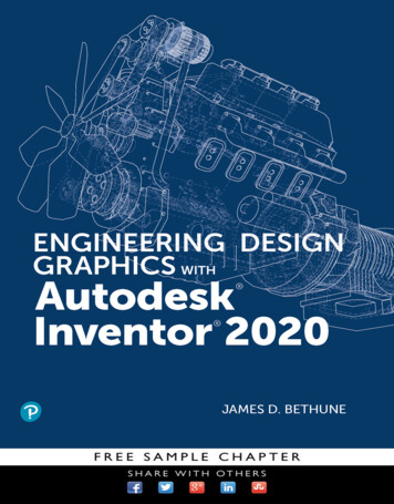
The structure of information1.1Hellman’s view of the problemProblems of communication comprehensive and sufficiently detailed for itspurposeThe Handbook of Architectural Practice andManagement (published by the Royal Institute of British easily retrievable from the mass of other informationwith which, inevitably, it will be combined.Architects) points out, ‘As with all technicalcommunication, the user’s needs are the primaryIt is the purpose of this book to consider these fourconsideration’. Whoever the user is—and the users of arequirements in detail and hopefully to proposeset of drawings will be many and various—he has thetechniques for satisfying them.right to expect that the information given to him will be:There is a fifth and fundamental requirement, of course. an accurate record of the designer’s intentionsThe information conveyed must be technically sound; clearly expressed and easily understoodif this is not the case then all the careful draughting and3
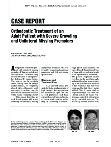
Working Drawings Handbook1.2House at Gerrards Cross by A. Jessop Hardwick, c. 1905. A typical working drawing of its era, inboth its draughting techniques and its obsessive use of every inch of the drawing sheet(RIBA Drawings Collection)4
The structure of informationcross-referencing will not be sufficient to prevent disaster. a source for the preparation of other documentsThis aspect, however, lies outside the scope of the present a statement of intent for the purpose of obtainingstatutory consentsbook which must concern itself only with the adequatedocumentation of technical decisions made at an earlier stage. In RIBA Plan of Work terminology, the decisionsbelong to stage E; their documentation belongs to stage F.The plan of worka framework for establishing nominated subcontractors or suppliers a source for the preparation of shop drawings a shopping list for the ordering of materials a construction manual a model for developing the construction programme a supervising documentSince what we shall be looking at is in effect a series of a record of variations from the contractdisciplines, and since the plan of work is the overriding a base document for measurement of the completeddiscipline into which the working drawing process isworks and preparation of the final accountsintegrated, it is probably worthwhile reminding ourselves a base document for defects liability inspectionof it at the outset. Table I of the outline plan of work is a record of the completed structuregiven here in its entirety. a source of feedback.Frequent reference to the plan of work will be made inthis book, for it is important that stage F productiondrawings should be seen in the context of the wholearchitectural process, forming the vital link between thedesigner’s intention and the builder’s execution of it. Thesuccessful implementation of many of the techniques tobe dealt with here will depend upon proper proceduresIt will be noted that the majority of these uses involvethe contractor and clearly his needs are paramount, ifonly for the purely legal reason that it is he who will becontractually committed to the employer to build whatthe architect tells him to. They may be separated intothree main activities and any drawing method mustsatisfy all three if it is to prove viable.having been carried out at earlier stages, whilst thewhole raison d’ être of the drawing set lies in the stagesfollowing its production.Activity 1: The procurement of all necessary materialsand components. For this the contractor will needthe following information in a form in which it can beThe usersThere are many users of a set of drawings and eachmay put it to more than one use. Unless the set is to beredrawn expensively to suit the ideal requirements ofeach, priorities must be established and compromisesaccepted. Consider the following functions of a set ofdrawings (the list is by no means exhaustive).identified readily and extracted for ordering purposes:A specification of the materials to be used, which can bereferred back simply to the drawings and the bills ofquantities.Drawings and schedules of all components which he is toprovide (doors, windows, etc.) and which constitutemeasured items in the bills of quantities.Drawings and schedules from which outsideIt forms for different people and at different times:manufacturers’ products may be ordered and whichprovide design criteria against which manufacturers’ a basis for tendering (‘bidding’ in USA) a contractual commitmentshop drawings may be checked.5
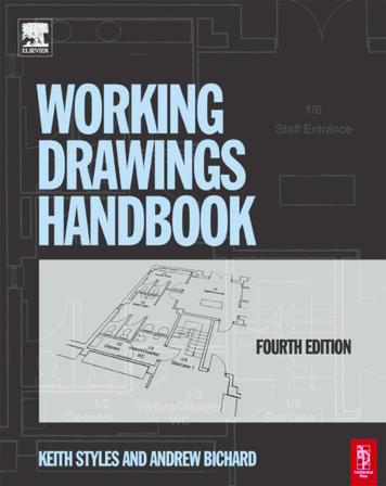
Working Drawings HandbookTable I The RIBA Plan of WorkFeasibilityAAppraisalIdentification of client’s requirements and of possible constraints on development. Preparation of studiesto enable the client to decide whether to proceed and to select the probable procurement method.BStrategic BriefingPreparation of Strategic Brief by or on behalf of the client confirming key requirements and constraints.Identification of procedures, organisational structure and range of consultants and others to be engagedfor the project.Pre-construction periodCOutline ProposalsCommence development of Strategic Brief into full Project Brief.Preparation of Outline Proposals and estimate of cost.Review of procurement route.DDetailed ProposalsComplete development of the Project Brief.Preparation of Detailed Proposals.Application for full Development Control approval.EFinal ProposalsPreparation of Final Proposals for the project sufficient for coordination of all components and elementsof the project.FProduction InformationF1 Preparation of production information in sufficient detail to enable a tender or tenders to be obtained.Application for statutory approvals.F2 Preparation of further production information required under the building contract.GTender documentationPreparation and collation of tender documentation in sufficient detail to enable a tender or tenders to beobtained for the construction of the project.HTender ActionIdentification and evaluation of potential contractors and/or specialists for the construction of the project.Obtaining and appraising tenders and submission of recommendations to the client.Construction periodJMobilisationLetting the building contract, appointing the contractor.Issuing of production information to the contractor. Arranging site hand-over to the contractor.KConstruction to Practical CompletionAdministration of the building contract up to and including practical completion.Provision to the contractor of further information as and when reasonably required.LAfter Practical CompletionAdministration of the building contract after practical completion.Making final inspections and settling the final account.The Work Stages into which the process of designing building projects and administering building contracts may be divided. (Some variations to the Work Stagesapply for design and build procurement.)Published by RIBA 1998. By permission of RIBA6
The structure of informationActivity 2: The deployment of plant and labour. For thismoving between different offices. Nothing is morehe will need:disruptive for architect, estimator and contract manageralike than to have to switch constantly from one workingDrawings showing the extent of each trade’s involvement.method to another.A ‘construction manual’ describing, by means of annotateddrawings, the way in which each trade is to operate andIt was with this in mind that the Project Informationwhich is explicit enough to ensure that no local queryingGroup (commonly known by its somewhat unfortunateor decision-making will be necessary.acronym) was set up to identify more precisely theAn objective and realistic description of the qualitystandards required and the methods to be employed.Activity 3: The preparation of a programme and decisionon a method of operation. For this he will need:reasons for the inadequacies in building informationpreviously noted.In the course of time the Group became transmuted intothe Construction Project Information Committee, uponwhich the main building professional and contractingorganisations are represented and which in 2003Drawings giving an overall picture of his commitment.published a sequence of Co-ordinated Project InformationComprehensive information about the constraints of site,(CPI) documents. These represent what is to date theaccess and programme.A summary of his contractual obligations.most comprehensive statement of intent regarding theachievement of better production information.Among other aspects they acknowledge the concept ofThe need for a unified systemdrawings, specifications and bills of quantities, togetherforming the complete information package, and despiteWhat we are looking for is a complete informationthe existence of ingenious alternative methods whichsystem which will satisfy these different userhave been devised for particular situations it is not therequirements and which will be at the same time:intention of this book to disturb that long-standingtripartite relationship. reasonably simple and economical to produce simple to understand and to use at all levelsConsideration will be given in a later chapter to what flexible enough to embrace information produced byinformation sometimes given on drawings may be morevarious offices—structural, M & E, etc.appropriate to the specification; but other than that thiscapable of application to both small and largebook will concern itself solely with drawings, regardingprojectsthem as the base documents in the information packageappropriate for use in both small and large producingwhich it is the role of the specification to amplify, the billsoffices.to quantify (1.3). The importance of the two latter points tends to beunderestimated. Given a standard method of procedureThe structure of working drawingsa common experience is gradually built up, not onlyamong contractors but among assistants moving fromEvery set of working drawings consisting of more thanone project to another within the office, or indeedone sheet is structured, for it represents a more or7
Working Drawings Handbook1.3 Drawings, specification and bills of quantities. Each has a clearly defined role in the building packageless conscious decision on the part of theRegulations for the erection of a garage is likely todraughtsman to put certain information on one sheetcontain a small-scale plan showing the site in relation toof paper and certain other information on others.the surrounding neighbourhood as well as aEven were the reason for doing so simply that theredimensioned plan of the building itself. This in effectis insufficient space on a single sheet of paper, aacknowledges the existence of some informationalselection has still to be made of what to put on eachhierarchy within which certain different aspects ofsheet and a sensible basis for that division has to beinstruction about the building may sensibly be given indetermined.different places and in different ways (1.4).Indeed, the simplest of single sheet applications to aIn the following pages we shall be not so much seekinglocal authority for approval under the Buildingto impose a method of doing this as seeking out the8
The structure of information1.4 Detail from an early example of elementalisation. Drainage plan byJames Adam, c.1775 (RIBA Drawing Collection)structure inherent in the whole concept of buildinginformation, and trying to reflect it in the form that theinformation package will take.What, where and how?The information that an operative needs to know abouteach element of the building he is called upon toconstruct may be classified into three distinct types:Let us start our search at the point where the ultimateend product of the entire communications exercise is tobe found—the building site.1 He needs to know what it is that he has to install orerect. Whether it be a window frame, brick or cubic9
Working Drawings Handbookmetre of concrete, he needs to know certain informa-The amount of information required so that the descriptiontion about its nature and physical dimensions.of any aspect of the building will be unambiguous must2 He needs to know where it is to be placed. Thisalways be a matter for intelligent consideration. Thedemands pictorial and dimensional informationstrength and density of bricks forming footings belowregarding its relationship to the building as a whole.ground level, for instance, will be fit subjects for precise3 He needs to know how it is to be placed or fixed indescription, whereas their colour will not.relation to its immediate neighbouring elements.But two fundamental principles emerge which will beClearly, these three questions—what, where and how—found to hold good at all times.are fundamental to the business of buildingcommunications, and demand a variety of replies inpractice if they are to be answered satisfactorily andwithout ambiguity. It may be useful to reflect for amoment on the degree of depth and comprehensivenessthat may be required of these answers.1 All building information may be classified into threebasic categories, depending upon which of the threebasic questions—how, where and what—it purports toanswer.2 All building information is hierarchic in its nature andproceeds from the general to the particular.If the designer has devised a precise solution to thebuilding problem set him by his client, then theinformation to be conveyed to the builder must be ofsufficient detail to enable the unique nature of thatsolution to be appreciated and converted into physicalbuilding terms by a variety of people, most of whom willbe unfamiliar with the original problem and unaware ofthe chain of thought processes which has given rise toits solution.This latter observation requires some discussion,because the sequence in which the three questionswhich were posed at the start of this section emergemay suggest that the seeker after information starts withthe component and its nature and then works outwardsto a consideration of where and how to install it. Thissequence is in fact occasionally true—the windowmanufacturer, for example, would tend to consider thetype of window he was being called upon to makebefore determining how many of them were in theSo if we are dealing with a window, the single question—building and how they were distributed throughout it.What window?—may proliferate into a large and variedseries: what are its overall dimensions; what does it lookBut in general terms the reverse is true. Almost every userlike; what material is it made from; what is its glassof the information package will wish to know that there is athickness; what furniture does it have; what are itswall of finite dimensions with windows in it which forms thefinishes? These and many other questions will ariseouter boundary of the building, before seeking tofrom consideration of the nature of a single component.determine the various forms that the windows might takeor the precise nature of the bricks and their pointing.Similarly we need to know where in the building it is tobe installed, implying the need for dimensionalSince this is also the manner in which the designer willinformation in three planes; and how it is to belogically work, there is little difficulty, and everyinstalled—how it sits in relation to the lintel above it, howadvantage, in devising a system in which the search forit relates to the vertical DPCs in the adjacent wallinformation starts with the question Where? The answercavities, how many fixing points are required and what isto this question indicates where the answers may bethe nature of their fixing. And so on.found to the supplementary questions What? and How?10
The structure of informationPrimary structuring—byinformation typeWhat has been outlined is a method of primary Component information, answering the question:what is the component like? Assembly information, answering the question: howstructuring of information according to its type, andare the various components to be related one towhich may be summarised and named as follows:another—how are they to be assembled?This type of structure and the search pattern it Location information, answering the questions: wheregenerates is illustrated in (1.5). It is to be noted that theare components to be built or installed and whereCPI recommendations adopt a similar method offurther information about them may be found?classification, the only difference being that location1.5 The fundamental search pattern generated by the questions What?, Where? and How?11
Working Drawings Handbookdrawings are termed ‘general arrangement drawings’.Nevertheless, they have a role to play and used sensiblyThe term ‘location drawing’ has long been establishedand with forethought they form an essential element inwithin the architectural profession and the mnemonicthe information package.SLAC (schedule, location, assembly, component) is incommon use. Nevertheless, it seems likely that the CPISome principles affecting schedulingterminology will become increasingly known and used.The term ‘general arrangement’ has in any case longTheir primary function is to identify and list componentsbeen used in the engineering disciplines and haspossessing common characteristics—e.g. windows,therefore been used throughout the remainder ofdoors, manhole covers, etc.this book.They should not attempt to provide comprehensiveinformation about the component; they should serveInto this neatly classified system must now berather as an index to where the relevant informationintroduced that somewhat hybrid creature, themay be found.schedule. It must be made clear at the outset thatthe term ‘schedule’ here referred to is confined tobasic lists of information—primarily aboutcomponents—which are more readily set out in thismanner than on the drawings. (The Schedule ofWorks, as envisaged in the CPI documents forsmaller projects, has a different function, more akinto the bills of quantities.)They should initiate a simple search pattern for theretrieval of component, sub-component and assemblyinformation.They are only worth providing if the component inquestion has more than one variable. For instance, ifyou have windows of three different sizes which areidentical in every other respect, then size is the onlyvariable and you may as well write ‘Window Type 1’ onthe general arrangement plan as ‘Window no. 1’. But ifeach window size may be fixed into either a brick wall orThe idea of using written schedules, or lists ofa pre-cast concrete panel then the assembly informationinformation, exists in most information systems and hasrequired is a second variable.its source in a variety of motives, not all of themWindow Type 1 may be combined with jamb detail type 1necessarily valid. It is assumed that they are economicalor type 2, and it is for this greater degree of complexityof drawing office time; that quantity surveyors,that it is preferable to prepare a schedule.contractors and suppliers alike all welcome them; andthat they provide a ready check that the informationconveyed is comprehensive.The great virtue of the schedule is that it can direct youto a vast amount of information about a givenThese reasons do not always stand up to closecomponent in a way that would be impossible by anyexamination. Schedules are only economical if they aresystem of direct referencing from a general arrangementsimpler than the drawings they replace; the architectdrawing. Consider a window—thirty-seventh, shall weshould not necessarily be doing other people’s jobs forsay, of fifty-one on the second floor of a multi-storeythem; suppliers more often than not produce their ownblock of offices. The method chosen for giving it aschedules because the architect’s schedule is not in aunique reference is unimportant for the moment—W2/37form which they find usable; and some schedulesis as good a piece of shorthand as any for theattempt to provide so much information in sopurpose—but it is obvious that this simple means ofcomplicated a form that mistakes and omissionsidentification may be shown equally on a drawing or areadily occur.schedule (1.6).12
The structure of informationThus, there are two ways of providing acatalogue of the windows on the job, in whichW2/37 is seen to take its place betweenW2/36 and W2/38. But if we were now to addto the drawing a fuller description of whatW2/37 in fact consists of, then we shouldmeet an immediate difficulty—there is just notspace to do it (1.7).Consequently, when it is considered thatthe information given only scratches thesurface of what the recipient really needsto know and that similar information willneed to be provided about W2/1 toW2/50—to name but the windows on thesecond floor—it becomes apparent that notonly will there be insufficient room on the1.6Simple identification of components may be recorded oneither a schedule or general arrangement plandrawing to make this method feasible butthere will be insufficient drawing office timeand money available to make it an economicstarter. The schedule does it so muchbetter (1.8).Given the presence of schedules in thepackage, the search pattern given in (1.5)becomes simpler and more directly focused.The general arrangement drawing is still thestarting point but now the searcher is directedfrom it to the schedule and from there to thevarious sources of assembly and componentinformation (1.9).Further consideration will be given later tothe most suitable format for schedules and1.7The general arrangement plan is an inappropriate medium forto the areas of information which lendrecording the diverse characteristics of each component. Detail of thisthemselves most readily to scheduling.order can only be given elsewhere—in a specification or in otherAll that remains to be settled for the momentdrawings to which the schedule points the wayis what sort of an animal this hybrid mostresembles. Is it a drawing or some other formof document? If a drawing, then what type ofdrawing is it?13
Working Drawings Handbook1.8The schedule provides a simple and economical index to a variety of informationtowards assembly drawing, general arrangementdrawing, specification, trade literature and, possibly, thebills of quantities. If considered as a drawing then itclearly possesses all the directive qualities of a generalarrangement drawing. But it will inevitably be of adifferent nature—and indeed size—from the othergeneral arrangement drawings in the package, and itsstatus as such puts it in an anomalous situation whenused in conjunction with other documents—as anadjunct to the bills of quantities, for example.Maximum flexibility in use is therefore achieved byacknowledging the hybrid nature of the schedulefor what it is and by treating it as an independentform of document in its own right, capable equally ofbeing bound into a s
The structure of information 3 Problems of communication The Handbook of Architectural Practice and Management (published by the Royal Institute of British Architects) points out, ‘As with all