Transcription
TREK-USER-0010TREKDELAY TOLERANT NETWORKING(DTN) TUTORIALJune 2021Approved for Public Release; Distribution is Unlimited.
TREK-USER-0010TABLE OF CONTENTSPARAGRAPHPAGE1Welcome .12Technical Support .13Delay Tolerant Networking (DTN).14Interplanetary Overlay Network (ION) .54.1 ION Administration Programs . 54.1.1 ionadmin .54.1.2 ionsecadmin .64.1.3 bpadmin .64.1.4 ipnadmin .64.1.5 cfdpadmin .64.1.6 ltpadmin .64.2 ION Configuration Files . 74.3 ION Feedback. 84.3.1 The ion.log File .84.3.2 Standard Output .94.4 The ION Application Programming Interface. 95TReK DTN Capabilities .95.15.25.35.45.55.66The ISS DTN Configuration.106.16.27HPEG Application . 9IONconfig Application . 10IONizer API. 10IONizer Application. 10CFDP Application (ION CFDP mode). 10CFDP Console (ION CFDP mode). 10Single Payload DTN Configuration . 10Overall ISS DTN Architecture . 12Step-by-Step Tutorials.137.1 Two Nodes. 137.1.1 IONconfig . 137.1.2 IONizer. 297.1.3 CFDP. 317.2 ISS Operations Configurations. 387.2.1 Auto Configure . 397.2.2 Quick Configure (Recommended Option) . 437.3 Two Nodes with LTP. 437.4 Command Line Options. 497.4.1 startion.bat and startion.sh. 507.4.2 startion autoconfig.bat and startion autoconfig.sh. 507.4.3 trek ionizer console. 508Terminology .51i
TREK-USER-0010FIGURESFIGUREPAGEFigure 1 A Simple DTN Example. 2Figure 2 A 4-Node DTN Example . 4Figure 3 Single Payload Simplified Architecture . 11Figure 4 ISS DTN Architecture . 12Figure 5 Two Node Example . 13Figure 6 IONconfig . 14Figure 7 IONconfig with Directory . 15Figure 8 IONconfig with Two Nodes . 15Figure 9 IONconfig with Two Connected Nodes . 16Figure 10 Node Properties . 17Figure 11 General Node Properties (Node 1535) . 18Figure 12 Configuration Properties. 19Figure 13 Configuration Properties (Node 1535) . 20Figure 14 Administration Properties. 21Figure 15 Bundle Protocol Properties. 22Figure 16 Bundle Protocol Properties (Node 1535). 23Figure 17 CFDP Properties. 24Figure 18 LTP Properties. 25Figure 19 Security Properties . 26Figure 20 Duct Properties. 28Figure 21 IONizer Main Window. 29Figure 22 IONizer with Config File Directory. 30Figure 23 IONizer Main Window After Staring ION. 30Figure 24 CFDP Application Main Window. 31Figure 25 CFDP Configure Dialog . 32Figure 26 CFDP with ION CFDP Mode Selected . 33Figure 27 CFDP Configure Dialog Options Tab . 35Figure 28 CFDP Configure Dialog Options Tab with Data. 36Figure 29 CFDP Active in ION CFDP Mode. . 37Figure 30 CFDP Main Window with Complete File Transfer Information . 38Figure 31 Four Node ISS Example . 39Figure 32 IONconfig 4-node ISS . 40Figure 33 Quick Configure Preferences . 43Figure 34 Two Node Example with LTP . 44Figure 35 LTP Properties. 44Figure 36 LTP Properties (Node 1535) . 45Figure 37 Duct Properties. 46Figure 38 Duct Properties (LTP Part 1). 48Figure 39 Duct Properties (LTP Part 2). 49ii
TREK-USER-0010TABLESTABLEPAGETable 1 ION Configuration Files Generated by IONconfig . 7Table 2 TReK Related Files Generated by IONconfig. 8Table 3 General Node Properties (Node 1535) . 18Table 4 Configuration Properties (Node 1535). 19Table 5 Bundle Protocol Properties (Node 1535) . 22Table 6 General Node Properties (Node 9000) . 26Table 7 Configuration Properties (Node 9000). 26Table 8 Bundle Protocol Properties (Node 9000) . 27Table 9 Configuration Parameters for ION CFDP. 35Table 10 Payload Ground Changes. 41Table 11 Payload Flight Changes . 42Table 12 Quick Configure Command Line Options. 51Table 13 Quick Configure Preference File Details . 51iii
TREK-USER-00101 WelcomeThe Telescience Resource Kit (TReK) is a suite of software applications and libraries thatcan be used to monitor and control assets in space or on the ground.This tutorial describes Delay Tolerant Networking (DTN) from an end user perspective.There is a general discussion on what DTN is and how it can benefit the InternationalSpace Station (ISS) payload community and others. A brief introduction is also providedfor the Interplanetary Overlay Network (ION) which is the DTN implementation used byTReK. The DTN related capabilities in TReK are described along with step-by-steptutorials.There are many new terms associated with DTN. These terms are defined when they arefirst used in the text of the document and also collected in the Section 8 of this document.2 Technical SupportIf you are having trouble installing the TReK software or using any of the TReKsoftware, please contact us for technical assistance:TReK Help Desk E-Mail, Phone & -3521 (8:00 a.m. - 4:00 p.m. Central Time)256-544-9353If you call the TReK Help Desk and you get a recording please leave a message andsomeone will return your call. E-mail is the preferred contact method for help. The email message is automatically forwarded to the TReK developers and helps cut theresponse time. The HOSC Help Desk (256-544-5066) can provide assistance as neededand is available 24x7.3 Delay Tolerant Networking (DTN)Computers attached to the terrestrial Internet are essentially always able to communicateand do so instantaneously. While there can be outages that prevent connectivity, theseoutages tend to be isolated and relatively short term. For communication between acomputer on Earth and one in orbit around Earth or on a deep space mission, the outagesare more frequent and of longer duration. Protocols such as TCP/IP that work great forterrestrial networks can have problems in space networks when connectivity is notcontinuous or there is a long delay in communications.Some programs such as ISS have implemented IP protocols for the space environment.This provides the ability for payload teams to use many of the same protocols common tothe terrestrial Internet with orbiting experiments. Payload teams can use application layerprotocols such as secure shell (SSH) to interact with their onboard payload. While1
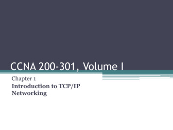
TREK-USER-0010communications with the payload are frequent and of relatively long duration for a spaceenvironment, they are not continuous.Delay or disruption in any path can cause problems in the transfer of data. The flight andpayload computers of space systems must often build specialized code to store the dataduring periods of disruption and send it when a transmission link becomes available. Ifdata is identified as lost on the receiving end, a means of requesting the retransmission oflost data must be provided. DTN can address this problem and alleviate the need for thistype of work.A delay tolerant network is composed of multiple computers or nodes. A singlecomputer can run one or more nodes although usually only a single node will exist on acomputer. The node is identified by a node number. The node number is unique acrossthe entire DTN. You can consider the node number the DTN equivalent of an IP address.It identifies what node sent the data and what node is to receive it. A computer withmultiple nodes is similar to a computer with multiple network cards/IP addresses.Each node has the knowledge of other nodes with which it may directly communicate andwhen those communication links are available. For nodes where direct communication isnot possible, DTN gateways can be used. Any DTN node that routes data from one DTNnode to another DTN node is considered a gateway. Gateways are usually not the finaldestination for the data, but can be. The data sent between nodes are called bundles. Abundle is the primary transfer block of data over a DTN 1. A simple example can helpillustrate this concept.Figure 1 shows a simple four node DTN with each node in series. Node 1 only knowshow to communicate with Node 2. Node 1 also knows when the communication link isavailable for Node 2. If Node 1 needs to send bundles to either Node 3 or Node 4, then itmust send the bundle through a gateway. In this case the gateway is Node 2. Node 1does not need to know when the communication links are available from Node 2 to Node3 or Node 3 to Node 4. It only knows that by sending the bundles to Node 2 the bundleswill get to the other nodes.Node 1Node 2Node 3Node 4Figure 1 A Simple DTN ExampleDTN can be used as a store and forward network since end-to-end communication is notalways possible. A node can send bundles to another node that will store the bundlesuntil it is possible to forward it to the next node. If custody transfer is implemented forThe Bundle Protocol Specification is available if you wish to review the details. Just type “RFC-5050”into your favorite search engine.12
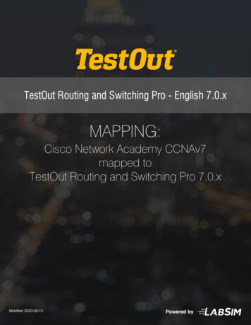
TREK-USER-0010the store and forward network, the node sending the bundle can safely delete its copy.Custody transfer is a request made from the node sending the data to the node receivingthe data. If the receiving node accepts custody of the data, the sending node can delete itscopy of the data. By accepting custody of the data the receiving node acceptsresponsibility for ensuring the data is transferred to the final destination or until it canpass custody to another node. By passing custody in this manner a single copy of thedata can be maintained in the DTN.Often a primary task of payloads is the transfer of files to and from the payload. Prior tothe availability of IP protocols onboard ISS, each payload team had to build a unique filetransfer protocol. Most often this involved splitting the file across multiple CCSDSpackets2 at the sending end and reassembling the file on the receiving end. If packetswere missing a mechanism to retransmit the missing data or the entire file had to beprovided.When IP protocols are available other means of data transfer is possible. If the plannedcommunication period and bandwidth available for contact with the spacecraft issufficient for the size of the file, standard file transfer mechanisms such as secure filetransfer protocol (SFTP) and secure copy (SCP) can be used. These means of filetransfer work well, but may have issues if communication is lost due to a planned loss ofsignal or an unplanned interruption.The CCDSS File Delivery Protocol3 (CFDP) helps alleviate the problems experienced bystandard network protocols by addressing the issues of delay and disruption. CFDP canhandle long delay in communications and also has the means of retransmitting the datathat is lost due to disruption. While it is possible to run CFDP over non-IP networks, itbecame available as a standard service for ISS when IP protocols were enabled. CFDPallows for better multiple contact file transfers, but often needs to be knowledgeableabout contact periods so that the timeouts and limits associated with the CFDP protocolbehave properly. CFDP can also be used with DTN. In these instances theretransmission of lost data is provided by the DTN protocols.DTN can provide extra services for end users that aren’t available with standard IPprotocols. The best way to explain some of the advantages of DTN is with a couple ofexamples. The first example will be a large file transfer from a spacecraft computersystem to the ground. The second example will be a file transfer from a ground computerto the spacecraft.For each of these examples we will use a four node configuration like the one shown inFigure 2. In this example the two gateways can communicate with each other, but the2The Consultative Commit for Space Data Systems (CCSDS) provides multiple international standards foruse in space programs. The Space Packet Protocol is document number CCSDS 133.0-B-1 and is availableon the CCSDS website at x.3The CFDP document number is CCSDS 727.0-B-4 and is available on the CCSDS website spx.3
TREK-USER-0010communication is not always available. The end nodes each have continuous contactwith their respective gateway.SpaceGateway(Node 3)Ground Node(Node 1)Flight Node(Node 4)GroundGateway(Node 2)Figure 2 A 4-Node DTN ExampleThe first example is transfer of a large file from the flight node to the ground node. Inour example, the transfer of the file from node 4 to node 3 can occur relatively quicklysince the nodes are continuously available for sending and receiving data. As the bundlescomposing the file arrive at node 3 they can be sent along to node 2 if there iscommunication available. Otherwise, node 3 stores the data and forwards it once a linkbecomes available. When the bundles arrive at node 2 they can be immediatelyforwarded to node 1 which will then reassemble the file.If node 1 is not connected to node 2 when the bundles arrive from node 3, node 2 willstore the bundles and forward them once node 1 is able to connect again. In this examplethe flight node and ground node are both shielded from knowing when a communicationlink is available. The gateway nodes handle that for them. Also, if a node is notavailable, data is stored and forwarded when the node is once again connected.The second example involves sending a file from the ground node to the flight node.Sending a file from the ground to the spacecraft is often a controlled activity. For thisexample, let’s assume that you need to uplink a configuration file to your flight node.Perhaps the operations team controlling the ground gateway is required to enable you forsending the file. If other users currently have priority, your first opportunity may conflictwith watching a very important football game. Instead of missing the game, you couldsend the file to the ground gateway and it would automatically uplink the file once uplinkis enabled by the operations cadre. If the scheduled time available for uplinking the fileshifted, the delay tolerant network will automatically be aware of the shift and with nointervention from you take care of the problem preventing you from missing the pregamebuildup or postgame celebration.4
TREK-USER-0010The disruptions and delays associated with space links are the primary motivations forestablishing delay tolerant networks. A properly designed DTN can insulate systemsfrom the knowledge of when contacts are available and provide a storage network thatincludes the automatic retransmission of missing data. While the above examples are filerelated the same principles can be applied to other types of data such as telemetry andvideo.4 Interplanetary Overlay Network (ION)Delay tolerant networking is described in RFC-4838 and includes several otherspecifications. Fortunately, several implementations of the DTN protocols are availableincluding the Interplanetary Overlay Network (ION) which is used by TReK. Thissection briefly describes ION and introduces a few ideas that are important inunderstanding how TReK works with ION.ION is written in C and is compatible on many different operating systems including theones supported by TReK. TReK provides a Windows installation with .lib files neededfor compiling with Visual Studio programs. An RPM file is also available for installationof RedHat Enterprise Linux 6.x systems. The ION source code 4 and TReK providedinstallation files include the ION design documentation as well as the description of theapplication programming interface provided by ION.ION is composed of many small processes and common libraries working together toprovide the entire set of DTN capabilities. These processes are managed through a seriesof administration programs and associated resource files. These resource files allow theuser to configure the delay tolerant network.4.1 ION Administration ProgramsThe following paragraphs describe the administration programs that are currently used byTReK and the general capabilities that each control. There are other administrationprograms in ION that are not discussed. The information provided can be helpful inunderstanding some of the TReK applications related to DTN. The administrationprograms are identified by their executable name.4.1.1 ionadminThe ionadmin program configures the DTN node and establishes the node number thatwill identify the node. Additionally, the simple data recorder (SDR) is created. The SDRin ION can reside in volatile memory, on the file system, or both. The memory optionallows for faster data retrieval while the file option provides non-volatile storage. TheSDR is sometimes referred to as a data store in this document. One of the importantconsiderations in configuring a DTN node with ION is the size of the SDR. ION uses aconfiguration item name identified as heapWords to determine the size of the SDR. The4ION source code is available for download at http://sourceforge.net/projects/ion-dtn/.5
TREK-USER-0010number of heapWords is multiplied by the number of bytes in the processor to determinethe actual size of the SDR. If heapWords is set to 1,000,000, then the SDR size on a 32bit computer will be 4 million bytes and on a 64-bit computer 8 million bytes.4.1.2 ionsecadminThe ionsecadmin program configures the security policy for ION. At this time, TReKonly initializes the security to prevent unwanted messages from appearing in the log file.4.1.3 bpadminThe bpadmin program configures the bundle protocol for the ION node. This includesidentifying the endpoints used by applications. Endpoints in DTN are used to segregatebundle traffic and route the appropriate data to the correct BP enabled application. Theendpoints in ION use the node number and a service number. The service number allowsION to route the bundle to an application that has registered to receive it. Just as you canconsider the node number as similar to an IP address, you can think of the service numberas a port number. For standard applications such as CFDP that are provided by ION, youdon’t need to worry about the endpoints. You will only need to add endpoints for BPenabled applications you provide.The bpadmin program also establishes which protocols (e.g., TCP) will be used withION. The protocols identify which convergence layers are used for the ION node.ION uses the terms ‘duct’ to specify communication paths between nodes. An induct isused to receive data from another node. An outduct is used to send data to another node.There is typically a single induct per protocol, but some protocols require an outduct foreach destination node.4.1.4 ipnadminThe ipnadmin program configures the plans for routing DTN bundles. The routes can beeither a direct connection or via DTN gateways (static routing).4.1.5 cfdpadminThe cfdpadmin program configures the ION provided implementation of CFDP. Thedefault values for CFDP should be sufficient for most users.4.1.6 ltpadminThe ltpadmin program configures the Licklider Transmission Protocol (LTP) for ION.LTP requires the knowledge of when transmission of data is available. In ION thisknowledge is provided by contact plans. LTP provides an efficient mechanism for theretransmission of missing data over disruptive links by providing checkpoints whichtrigger the node receiving the data to report on what data has been received and what is6
TREK-USER-0010missing. For the typical 4-node ISS implementation LTP is implemented at the gatewaynodes and is not needed by the ground or payload flight computers. However, if one orboth gateway nodes are not available LTP can be enabled on the payload flight or groundcomputer as needed to ensure efficient retransmission of data.4.2 ION Configuration FilesThe IONconfig application will generate all of the files needed to run ION. Table 1shows all of the files generated by IONconfig that are used by ION administrationprograms. Table 2 shows the other files that are generated that are related to TReKoperations. Some of these files can also be used without TReK. Items in Table 2 markedby an asterisk (*) are only applicable for nodes connecting to ISS via the HOSC toPayload Ethernet Gateway (HPEG).Filecontact onrcDescriptionAn ION configuration file that describes contact times betweennodes. Only applicable when LTP 5 is used.Contains the information for the ION bpadmin program to
This tutorial describes Delay Tolerant Networking (DTN) from an end user perspective. There is a general discussion on what DTN is and how it can benefit the International Space Station (ISS) payload community and others. A brief introduction is also provided for the Interplanetary Over