Transcription
White PaperEvaluation of the DirectDensity Algorithm forEnergy‐IndependentRadiotherapy TreatmentPlanningAlisha Shutler1, Abhirup Sarkar1, Guillaume Grousset2, Jainil Shah2, Firas Mourtada11Radiation Oncology Dept., Helen F. Graham Cancer Center, Christiana Care, Newark, DE2Siemens Healthineers USA, Malvern, PAsiemens-healthineers.us
White Paper · Evaluation of the Direct Density Algorithm for Energy-Independent Radiotherapy Treatment PlanningAbstractPurpose: The commonly accepted practice in RT is to image all patients at 120kVp in order to avoidpotential errors with the energy dependent electron/mass density calibration curve. While this issafe practice, the disadvantage is in missing potential superior soft tissue contrast when you varythe tube voltage. A novel Direct Density (DD) algorithm is available to allow use of energyindependent CT# to density, simplifying clinical workflow with one calibration curve. In order tocommission DD for our clinic, we compared the dose calculated from DD reconstructed CT imagesat a variety of tube potentials to doses produced using the standard 120kVp images.Methods: Four different phantom studies were conducted. Two with tissue equivalent slabs(homogenous solid water and heterogeneous using ICRU slabs (solid water, bone, and lungequivalent slabs)); and two using thorax Rando phantoms. Scans were performed using a standardreconstruction at 120 kVp and a DD reconstruction for differing kVp (70 – 140kVp) on a SOMATOMDefinition Edge (Siemens GMBH, Forchheim, Germany). Two distinct CT density curves wereimplemented in the treatment planning system (RaystationV9) to read both standard and DDimages. Average CT numbers for each ROI were recorded. Point doses were calculated andmeasured for 200 MU AP plans at 6, 10, and 15 MV, and dose differences were compared. TheRando phantoms were scanned using both kernels at 120kVp, and a VMAT plan was simulated oneach. DVH plots were created for assessment.Results: In all instances, computed DD doses were nearly identical to the standard kernel dose.Point dose measurements differed by 1%. The largest difference was for the 70kVp AP plan,producing dosimetric error of around 3cGy. VMAT plans showed negligible differences.Conclusions: With an appropriate CT density curve, DD reconstruction algorithm is as accurate asstandard algorithms at dose prediction, but allows the flexibility of using variable kVp to improveimage quality for certain tissues.Alisha Shutler, M.S.Medical Physics ResidentRadiation Oncology,Helen F. Graham Cancer Center& Research Institute4701 Ogletown-Stanton RdChristiana Care Health SystemNewark, DE 19713Chief of Clinical PhysicsRadiation Oncology,Helen F. Graham Cancer Center& Research Institute4701 Ogletown-Stanton RdChristiana Care Health SystemNewark, DE 19713Guillaume Grousset, Ph.D.Advanced Therapy - RadiationOncology KOL EngagementSiemens Healthineers40 Liberty Boulevard,Malvern, PA 19355Abhirup Sarkar, M.S., DABRTel: 302-623-4691Jainil Shah, Ph.D.Radiation Oncology,Helen F. Graham Cancer Center& Research InstituteEmail:fmourtada@christianacare.orgR&D Collaborations Manager– CTfor Radiation Oncology,Siemens Healthineers4701 Ogletown-Stanton RdChristiana Care Health SystemNewark, DE 197132Firas Mourtada,M.S.E.,Ph.D., DABR, FAAPM221 Gregson DriveCary, NC 27511
Evaluation of the Direct Density Algorithm for Energy-Independent Radiotherapy Treatment Planning · White PaperContentsIntroductionBrief Background:What is Direct Density?Implementation:How can my TPS readRED values via CT#s?Creating the CT-MassDensity CurveVerification:Does the Direct Densitykernel work?Do the CT #s remainconstant?Thorax phantomsevaluationDiscussionConclusions3
White Paper · Evaluation of the Direct Density Algorithm for Energy-Independent Radiotherapy Treatment PlanningIntroductionSiemens Healthineers has recently introduced DirectDensity (DD), a novel technique that allows the reconstruction ofimages acquired at any kV to be directly interpreted aselectron density images, thus eliminating the need toperform a Hounsfield Unit (HU) to electron densitycalibration. While the principles behind DD have beensummarized in an earlier white paper1, incorporating anew technology in the clinic can often be challenging andtime consuming. While as a community we continue toexplore how best to integrate the new technology in theclinic, the goal of this work is to establish a step-by-stepmethodology to assist the successful implementationof DD in clinical routine. In this paper, we describe thecommissioning process at our clinic and present on thedose calculated from DD reconstructed CT images at avariety of tube potentials to doses produced using the120kVp reconstructed images using the standardfiltered back projection (FBP) algorithm.Brief BackgroundWhat is Direct Density?Direct Density is a reconstruction algorithm/kernel (not to beconfused with Siemen’s Dual Energy scanning protocol) thatprovides HUs scaled to the Relative Electron Density. (Thesescaled HU values will be referred to as CT #s.) The CT #s areenergy independent, meaning that any scan, at any energy,will produce values that give an accurate representation ofthe true relative electron density or relative mass density(RD or relative density) of the material. This can be especiallyuseful for differentiation of soft tissues that would benefitfrom lower energy scans, or scans requiring the use of higherenergies for harder density materials; no matter the energyused, by selecting the direct density reconstruction, the RDvalue doesn’t vary with energy. Since it represents a physicalproperty of the materials, the CT #s, which directly thenrepresent the RD, will remain the same.4
Evaluation of the Direct Density Algorithm for Energy-Independent Radiotherapy Treatment Planning · White PaperImplementationHow can my TPS read RD values via CT#s?CT #s are simply RD values that have been scaled so that theyresemble traditional HUs:RD CT # 10001000In modern treatment planning systems (TPS), the HU tomass density function is usually required to perform dosecalculations. Similarly, for DD implementation, CT#s to massdensity function will be required and then inputted into theTPS. This can be accomplished by scanning the CT Densityphantom, as usually done now in the clinic, with knownmass density plugs (it is recommended that scans performedusing these phantoms use plugs that range in density fromvery low to very high, or near zero to roughly 3-4 g/cm3).After the CT acquisition and applying the DD recon kernelSd-40, each plug is contoured as a Volume-of-Interest (VOI)and then a table that relates the average CT #s for eachVOI and its mass density can be created. This table canthen be entered into the TPS.Relative electron densityDirectDensity image value0.000-10001.00004.0723072Table 1 RED to CT#s values provided by Siemens Healthineers5
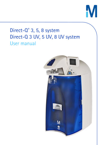
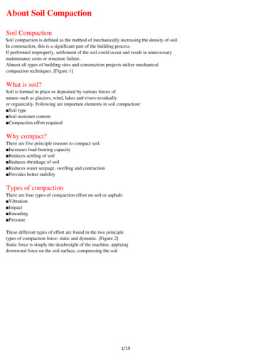
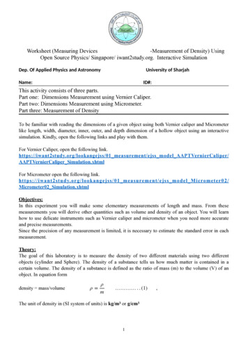
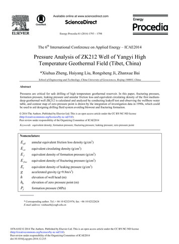
White Paper · Evaluation of the Direct Density Algorithm for Energy-Independent Radiotherapy Treatment PlanningCreating the CT‐ Mass Density CurveA high quality CT Density Phantom, such as CIRS (Norfolk,VA, U.S.A.) and Gammex (now Sun Nuclear, Middleton,WI, U.S.A.) should be used. These phantoms are composedof tissue-equivalent materials with a variety of “plugs,” ordifferent density materials, ranging in composition fromlung to dense bone or even titanium, duplicated aroundboth an inner and an outer ring.To verify that the Direct Density kernel mapped all tissuedensities to the appropriate mass density, the densityphantom was scanned at 70, 80, 100, 120, and 140 kVp,respectively, using a standard, clinical acquisition protocolof Br38 and then reconstructed using the DD Sd40 kernel.For comparison, the density phantom was also scannedwith conventional 120kVp protocol and reconstructedusing a standard FBP kernel (Br38). VOIs were created foreach plug type, using a single ROI for both the inner plugand outer plug of a given tissue equivalent materials (e.g.two “exhale lung” plugs both were contoured under thesame VOI name). The ROIs were expanded volumetricallyto include as much of the plug as possible without takingthe VOI to any edge, resulting in volumes of around 20cm3 for all but the smallest plugs. Average CT #s werenoted for each ROI, per energy, and plotted in a table withtheir physical mass density provided by the vendor of theCT density phantom.Figure 1 CIRS model 62 density phantom shown with water plug incenter (syringe). Titanium plug not pictured.To ensure that the TPS is reading the materials densitiesproperly, plots were constructed from the CIRS CT densityphantom and compared to that provided bySiemens Healthineers’ literature (Fig. 3).In the treatment planning system (TPS), in order to havea single mass density curve for all energies, the new CT‐Mass Density curve was created by entering the averageCT# over the ROI produced by all Direct Density scans(70 – 140 kVp) for each material plug.6Figure 2 Contoured ROIs for each plug on the CT density phantom
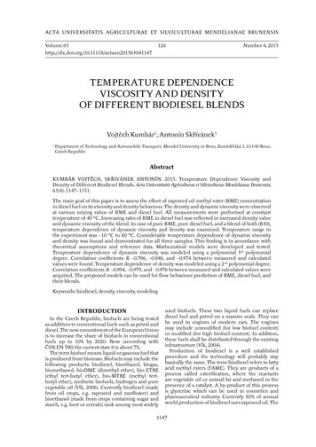
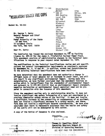
Evaluation of the Direct Density Algorithm for Energy-Independent Radiotherapy Treatment Planning · White PaperPhysicalDensity(g/cm3)Sd4070 kVpCT#Sd4080 kVpCT#Sd40100 kVpCT#Sd40120 kVpCT#Sd40140 kVpCT#-955-955-955-955-955-955.0-955.00.00121Lung 195Lung 43.053.01.071Trabecular Bone116.4123114.52118.65116.2117.7208.01.161Dense um290729122918294129532926.23072.04.51AirSd40 AVG Br38 AVGCT#CT#Table 2 Average CT# per VOI per energy for the CIRS CT Density Phantom reconstructed using both Direct Density (Sd40)and a standard, Br38 kernel used on a 120 kVp image2.52.0Standard 120 kVp KernelAverage DD KernelMassDensity(g/cm3)1.570 kVp DD80 kVp DD100 kVp DD1.0120 kVp DD140 kVp DD0.50-1500.0The plotted lines are not visiblebecause of the small difference-1000.0-500.00.0500.01000.0CT #Figure 3 CT # to mass density curve taken using Sd40 (Direct Density) scans at various energies and comparingthis curve to the traditional density curve done at 120 kVp for a standard, Br38, reconstruction kernel7
White Paper · Evaluation of the Direct Density Algorithm for Energy-Independent Radiotherapy Treatment PlanningVerificationIs the Direct Density kernelaccurate for dose calculation?Several material slabs of different densities wereassembled, scanned using the Siemens HealthineersEDGE CT scanner in our radiation oncology department,and reconstructed using the DD kernel. The first setupwas for a homogenous phantom of solid water only. Thesecond setup was for a heterogeneous phantom using amixture of solid water, lung, and bone tissue-equivalents.1. Homogenous PhantomA TPS plan was created in the TPS (Raystation V9A,RaySearch, Stockholm, Sweden) to deliver 200 MUs tothe homogenous slab configuration. Absorbed dosemeasurements were made and compared to thepredicted dose from the TPS. Table 3 depicts the CT#sfor the homogenous phantom using both version ofsyngo.via VB10 and VB20, indicating the importance ofrecommission when the software version has changed.Table 4 depicts the dosimetric point dose results for thestandard 120 kVp Br38 kernel and the Sd40 DD kernels.Point doseSolidWater12 cm30 cmFigure 4 Homogenous slab setup8
Evaluation of the Direct Density Algorithm for Energy-Independent Radiotherapy Treatment Planning · White Papersyngo.via VB20CT#Br38 120kVp23.73Sd40 120kVp21.97Sd40 70kVp21.01Sd40 80kVp22.96Sd40 100kVp22.75Sd40 140kVp21.44Sd40 Ave. CT#22.03%CV3.8%*Data could not be acquired retrospectivelyTable 3 Average CT #s reported by Raystation TPS for the homogenous solid waterphantom for syngo.via VB20. %CV is percent coefficient of variation6 MV Dose (cGy)10 MV Dose (cGy)15 MV Dose (cGy)Br38 120kVp165175179Sd40 120kVp165175179Sd40 70kVp165175179Sd40 80kVp165175179Sd40 100kVp165175179Sd40 140kVp165175179Average Dose165175179%CV0%0%0%Table 4 Predicted Dose from 200 MUs at 100 SSD for the Homogenous Phantom for photon energy of 6, 10, and 15 MV, respectively.All TPS results are calculated for the syngo.via VB20. Ave Dose is for Br38 and Sd40 kernels. %CV is percent coefficient of variation9
White Paper · Evaluation of the Direct Density Algorithm for Energy-Independent Radiotherapy Treatment Planning2. Heterogenous PhantomA TPS plan was created in the Raystation(V9A, RaySearch, Stockholm, Sweden)to deliver 200 MUs to the heterogenousslab configuration, consisting of ICRUslabs of solid water, bone, and lung(Fig 5). Absorbed dose measurementswere made and compared to thepredicted dose from the TPS. Table 4depicts the CT#s for the heterogenousphantom using syngo.via VB20. Table 5depicts the dosimetric point doseresults for the standard 120 kVpBr38 kernel and the Sd40 DD kernels.Table 6 shows the ion chambermeasurements to those calculated byRaystation for both phantoms, for thethree photon energies used in our clinic.SolidWater5 cmBone1 cmLung5 cmBone1.5cmPoint doseSolidWater7 cm30 cmFigure 5 Heterogenous slab configurationSolid Water Solid Water –Top Solid Water –BottomCT#CT#CT#LungCT#BoneCT#Bone–Top Bone–BottomCT#CT#Br38 120kVp51.444.754.9-653.5438.9262.8447.7Sd40 120kVp46.640.949.8-657.9279.9150.2288.3Sd40 70kVp46.835.653.0-625.1199.7108.3206.1Sd40 80kVp49.639.955.1-637.9218.5122.0224.6Sd40 100kVp45.635.451.8-649.2249.0136.9256.4Sd40 140kVp44.135.9749.1-660.5296.2161.2306.1Sd40 Ave. %1.3%1.3%1.3%1.3%Table 5 Average CT #s as reported by Raystation TPS for the Heterogenous Phantom, see Figure 6 for the slab arrangement. The “Solid Water” and“Bone” columns are the averages of the Top and Bottom solid water and bone columns, respectively. %CV is percent coefficient of variation.10
Evaluation of the Direct Density Algorithm for Energy-Independent Radiotherapy Treatment Planning · White PaperPredicted Dose from 200 MUs at 88 SSD for Heterogenous Phantom6 MV Dose (cGy)10 MV Dose (cGy)15 MV Dose (cGy)Br38 120kVp142155161Sd40 120kVp142155161Sd40 70kVp141154160Sd40 80kVp142154161Sd40 100kVp142155161Sd40 140kVp142155161Average Dose141.8154.6160.8%CV1.4%1.1%1.4%Table 6 Depicts the dosimetric point dose results for the standard 120 kVp Br38 kernel and the Sd40 DD kernels. Ave Dose is forBr38 and Sd40 kernels. %CV is percent coefficient of variation. SSD Source-to-Surface Distance, MU Monitor UnitsTPS Dose (DD)(cGy)Measured Dose(cGy)% Difference6 %10 %15 %Table 7 Ion chamber point dose measurements for the 1) homogenous phantom setup and 2) the heterogenous phantom setup.TPS calculations performed with the average DD curve shown in Figure 5.11
White Paper · Evaluation of the Direct Density Algorithm for Energy-Independent Radiotherapy Treatment PlanningDo the CT #s remain constant?A Sensitivity Analysis1.0181.0131.0081.0030.998Relative DoseVariations of the CT #s were the most pronouncedwhen comparing the difference between the DD(Sd40) kernel at 70 kVp and at 120 kVp. However,clinically, these differences appeared to result indose differences of less than 1% as shown inFigures 6 and 7 (right).Ratio of 120 kVp Sd40 to 120 kVp Br38 311.112.012.913.714.615.416.317.2There were some data during our investigationthat suggested that CT #s for lower density materialschanged for scans that contained both low and highdensity materials. This is likely due to the method inwhich the DD kernel searches for and establishesbone densities first, in conjunction with the nontypical case of large heterogeneous slabs of boneon top of soft-tissues (see Discussion section).Depth in Phantom (cm)Solid water–bottomBone–bottomLungBone–topSolid water–topFigure 6 Ratio of calculated line doses through the heterogenous phantomfor two scans at 120 kVp, one using a standard Br38 reconstruction kerneland the other using DDRatio of 70 kVp Sd40 to 120 kVp Br38 Dose1.0181.0081.0030.998Relative 311.112.012.913.714.615.416.317.20.988Depth in Phantom (cm)Solid water–bottomBone–bottomLungBone–topSolid water–topFigure 7 Ratio of calculated line doses through the heterogenous phantomfor two scans, one using standard reconstruction at 120 kVp Br 38 and theother using DD at 70 kVp Sd4012
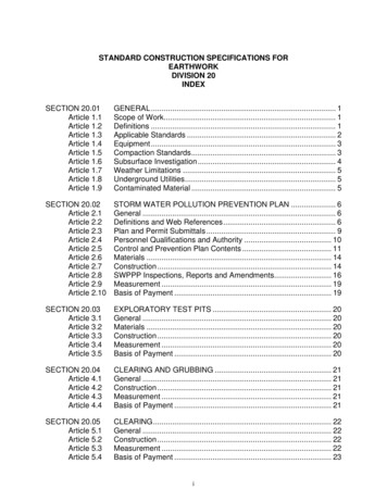
Evaluation of the Direct Density Algorithm for Energy-Independent Radiotherapy Treatment Planning · White PaperThorax Phantoms evaluationThe performance of the Sd40 kernel was also evaluatedon heterogenous phantoms that are more clinicallyrealistic. Two different humanoid phantoms were usedfor this investigation - the IROC-Houston lung phantom2and an in-house RANDO Thorax phantom.A. T he IROC lung phantom model, as shown in Figure 8,is well described in the literature2. It was scannedusing the Siemens Healthineers EDGE scannerwith the standard 120 kVp Br38 FBP and thenreconstructed with 120 kVp Sd40 direct densitykernel. No dosimetric differences were seenbetween any of the VMAT plans (Fig 9) asshown in the DVH results below were essentiallyidentical (Fig 10).Figure 8 Images from: Steinmann, A., Alvarez, P., Lee, H., Court, L., Stafford, R.,Sawakuchi, G., Wen, Z., Fuller, C. and Followill, D. (2019), MRIgRT dynamic lungmotion thorax anthropomorphic QA phantom: Design, development, reproducibility,and feasibility study. Med. Phys., 46: 5124-5133. doi:10.1002/mp.13757 and rpc.mdanderson.org/RPCFigure 9 VMAT plan on PTV on IROCphantomFigure 10 DVH comparison for VMAT plan on IROC phantom using Br38 and Sd40 imagestaken at 120 kVp. DVHs are overlapped and no difference detected13
White Paper · Evaluation of the Direct Density Algorithm for Energy-Independent Radiotherapy Treatment PlanningB. Rando thorax phantom: This method of clinicalverification was repeated for a more complex,more true-to-life Alderson RANDO thorax he-alderson-radiation-therapy-phantom/). CT #swere noted for relevant ROIs, then 3D plans andVMAT plans were made on a standard kernel imageat 120 kVp and on Direct Density images taken atall available kVp (140-70 kVp).Figure 11 Alderson RANDO phantom used to verify DD-based dosecalculations in RaystationCT Recon KernelPTVLeft LungRight LungHeartCordSternumBr38 120 kVp-44.5-507.3-507.625.642.5146.4Sd40 120 kVp-47.4-504.0-504.423.649.063.7Sd40 70 kVp-62.2-499.3-501.514.048.662.0Sd40 80 kVp-51.1-500.0-503.316.747.466.0Sd40 100 kVp-47.6-500.2-503.320.747.667.7Sd40 140 kVp-57.1-504.7-508.530.747.264.0Sd40 Average 30.6%1.7%3.4%Table 7 CT#s for Rando Thorax phantom14
Evaluation of the Direct Density Algorithm for Energy-Independent Radiotherapy Treatment Planning · White PaperCT Recon KernelCalc Point cGyMax Dose cGyPTV Average Dose cGyBr38 1204,6005,3274,676Sd40 1204,6005,3304,676Sd40 704,6005,3284,689Sd40 804,6005,3404,692Sd40 1004,6005,3454,694Sd40 1404,6005,3284,692Average Dose (cGy)4,6005,3334,686.50%0.1%0.2%%CVTable 8 Predicted Dose for 3D Rando Thorax PlansCT ScanDose at Volume,cGyMax Dose,cGy% PTV at 5000,cGyHeart Dose,cGyBr38 1205,0145,65896.3656Sd40 1205,0335,66697.9167Sd40 705,0345,55298.4567Sd40 805,0665,72199.671Sd40 1005,0285,48298.8272Sd40 1.2%11%Average Dose (cGy)%CVTable 9 Predicted Dose for VMAT Rando Thorax Plans15
White Paper · Evaluation of the Direct Density Algorithm for Energy-Independent Radiotherapy Treatment PlanningDiscussionOur results indicate that the DD algorithm has produced CT#swith a variance from the original 120kVP Br38 kernel (filteredback projection (FBP)) used in our clinic. It is important torealize this and evaluate the magnitude of the dosimetricimpact. This is expected since DD relies on single energy twomaterial decomposition, there are of course slight variationsin CT values depending on the setting/patient.Siemens Healthineers indicates that variations in the orderof up to 20-25 CT #s are normal and to be expected.As shown in Table 4, the largest deviation in CT#s is foundin the bone area (CT# of 33) for the heterogenous slabphantom. As always in CT (and especially for corrections andreconstruction), assumptions are made on the objects thatare typically to be imaged in clinical situations (i.e. patients).Some of those assumptions are: an overall oval shape, thehigh-density objects are bones (or implants) and that theyare always “far” from the edges of the patient (in otherwords, we assume that the patient is always surrounded bysome fat/soft tissue). The design of presented heterogeneousphantom is typical of an RT phantom (successive layers ofmaterial with a hole for an ion chamber, etc. ). This istypically used to verify predicted delivered dose for externalbeam, but those phantoms are suboptimal for imagingstudies, due to their abrupt heterogenous nature, and usersshould exert caution when analyzing results obtained withthose type of phantoms. The square design causes someserious challenges from a “patient outline” continuitystandpoint, which can significantly affect the homogeneityof the CT values within the object. Secondly, one shouldconsider the fact that when the CT tube is either at 90degrees or 270 degrees (assuming the 0 degree position isabove the phantom), the x-ray beam “sees” 2 slabs of bonethat have the same thickness as the object (which of coursegoes against the assumption we make as to what a patientusually looks like). This creates some significant disturbancein the sinogram and has non-negligible beam hardeningeffects that would also translate to variations in CT values.The dosimetric impact was largest for the 70 kVp Sd40, andon the order of 1% compared to the standard Br 38 120kVpkernel dose predictions.16
Evaluation of the Direct Density Algorithm for Energy-Independent Radiotherapy Treatment Planning · White PaperSeveral reports using clinical patient data have reachedsimilar findings. Flatten et al conducted a phantom study(simple and anthropomorphic) which also included metallicimplants. Differences were found mainly in pure air andhigh-density materials such as bones3. The difference of themean dose was below 0.7%, in most cases below 0.4%. Noindication was found that the algorithm is corrupted bymetal inserts, enabling the application for all clinical cases.van der Heyden et al performed a retrospective study onthe accuracy of DD dose calculation using 33 patients withvarious cancer types4. All CT acquisitions were reconstructedwith the standard FBP and DD. The mean tumor doses andthe volume percentage that receives more than 95% of theprescribed dose were calculated for the planning targetvolume. Relevant parameters for the organs at risk for eachtumor site were also calculated. The relative mean dosedifferences between the standard 120 kVp FBP CT scanworkflow and the DD CT scans (80, 100, 120 and 140 kVp)were in general less than 1% for the planned target volumeand organs at risk.Changes to Clinical WorkflowImplementing DirectDensity in the clinic is fairlystraightforward. As stated, a new CT Density curvewill need to be created in the TPS. Then, appending theDirectDensity reconstruction as a secondary reconstructionfor all existing protocols, will also need to be done. In thismanner, physicians will be able to use the standard protocol,done at a different kVp from the usual 120 kVp, to drawthe GTV/CTV and OARs contours with the benefits ofenhanced tissue contrast. Dosimetry/Physics will mapthe contours using rigid registration tools in the TPS tothe DD-reconstructed image and continue with treatmentplanning as normal.17
White Paper · Evaluation of the Direct Density Algorithm for Energy-Independent Radiotherapy Treatment PlanningConclusionsWith an appropriate CT density curve, DD reconstructionalgorithm is as accurate as standard algorithms at doseprediction but allows the flexibility of using variable kVpto improve image quality for certain tissues. Our nextstep is to implement DirectDensityTM for routine clinicalCT simulation in our clinic. Future report of the clinicaloutcomes will be documented in Part II of this white paper.18
Evaluation of the Direct Density Algorithm for Energy-Independent Radiotherapy Treatment Planning · White PaperNotes19
At Siemens Healthineers, our purpose is to enablehealthcare providers to increase value by empoweringthem on their journey toward expanding precisionmedicine, transforming care delivery, and improvingpatient experience, all enabled by digitalizing healthcare.An estimated 5 million patients globally benefit everyday from our innovative technologies and servicesin the areas of diagnostic and therapeutic imaging,laboratory diagnostics, and molecular medicine, aswell as digital health and enterprise services.We’re a leading medical technology company withover 120 years of experience and 18,500 patentsglobally. With about 50,000 dedicated colleagues inover 70 countries, we’ll continue to innovate andshape the future of healthcare.On account of certain regional limitations of salesrights and service availability, we cannot guaranteethat all products included in this brochure areavailable through the Siemens Healthineers salesorganization worldwide. Availability and packagingmay vary by country and is subject to changewithout prior notice. Some/All of the features andproducts described herein may not be available inthe United States.The information in this document contains generaltechnical descriptions of specifications and optionsas well as standard and optional features, which donot always have to be present in individual cases.Siemens Healthineers reserves the right to modifythe design, packaging, specifications, and optionsdescribed herein without prior notice. For the mostcurrent information, please contact your local salesrepresentative from Siemens Healthineers.Note: Any technical data contained in this documentmay vary within defined tolerances. Original imagesalways lose a certain amount of detail when reproduced.References1 Ritter, Direct Density: Principles and Implications for RadiotherapySiemens Healthineers White Paper.2 Steinmann, A., et al., MRIgRT dynamic lung motion thoraxanthropomorphic QA phantom: Design, development, reproducibility,and feasibility study. Med Phys, 2019. 46(11): p. 5124-5133.3 Flatten, V., et al., A phantom based evaluation of the dose predictionand effects in treatment plans, when calculating on a direct densityCT reconstruction. J Appl Clin Med Phys, 2020. 21(3): p. 52-61. 4 van der Heyden, B., et al., Clinical evaluation of a novel CT imagereconstruction algorithm for direct dose calculations. Physics andImaging in Radiation Oncology, 2017. 2: p. 11-16.The scientific overlay is not that of the individual pictured and is not from a device of Siemens Healthineers.It was modified for better visualization.Siemens Healthineers HeadquartersSiemens Healthcare GmbHHenkestr. 12791052 Erlangen, GermanyPhone: 49 9131 84-0siemens-healthineers.comUSASiemens Medical Solutions USA, Inc.Healthcare40 Liberty BoulevardMalvern, PA 19355-9998, USAPhone: 1-888-826-9702siemens-healthineers.usPublished by Siemens Medical Solutions USA, Inc. · Order No. RO-20-NAM-1086 · Printed in USA · 07.2020 · Siemens Medical Solutions USA, Inc., 2020
Helen F. Graham Cancer Center & Research Institute 4701 Ogletown-Stanton Rd Christiana Care Health System Newark, DE 19713 Alisha Shutler, M.S. Medical Physics Resident Radiation Oncology, Helen F. Graham Cancer Center & Research Institute 4701 Ogletown-Stanton Rd Christia