Transcription
Introduction to TransformersCourse No: E05-013Credit: 5 PDHElie Tawil, P.E., LEED APContinuing Education and Development, Inc.22 Stonewall CourtWoodcliff Lake, NJ 07677P: (877) 322-5800info@cedengineering.com
Transformers:Basics, Maintenance,and DiagnosticsU.S. Department of the InteriorBureau of ReclamationApril 2005
Transformers:Basics, Maintenance,and DiagnosticsU.S. Department of the InteriorBureau of ReclamationTechnical Service CenterInfrastructure Services DivisionHydroelectric Research and Technical Services GroupDenver, ColoradoApril 2005
PREFACETransformers have been used at powerplants since the inception ofalternating-current generation, a century ago. While operatingprinciples of transformers remain the same, the challenges ofmaintaining and testing transformers have evolved along withtransformer design and construction. Modern transformers aredesigned to closer tolerances than transformers in the past. Thus,effective, regular maintenance and testing is even more essential tocontinued operation when traditional “overdesign” cannot be relied onto overcome abnormal conditions. The utility engineer must befamiliar with all aspects of maintenance and testing and make use ofstate-of-the-art tools and techniques for evaluating transformercondition. While on-line diagnostic systems and computerized testingmethods are very helpful, they are not a substitute for soundengineering judgment and expertise.This volume provides timely, practical advice to those seeking tobetter understand how transformers work, how they are bestmaintained, and how to test and evaluate their condition. It has beendeveloped with the assistance of Bureau of Reclamation engineersresponsible for operating and maintaining transformers at importantpowerplants in the Western States. Support and funding was providedthrough the Reclamation Power Resources Office in Denver and viathe Manuals and Standards development program.The authors gratefully acknowledge the assistance of all whocontributed.Hydroelectric Research andTechnical Services GroupDenver, ColoradoApril 2005iii
Transformers:Basics, Maintenance, and DiagnosticsContentsPage1. Introduction.12. Introduction to Transformers .2.1 Principle of Operation.2.2 Transformer Action.2.3 Transformer Voltage and Current.2.4 The Magnetic Circuit .2.5 Core Losses.2.6 Copper Losses.2.7 Transformer Rating.2.8 Percent Impedance .2.9 Internal Forces .2.10 Autotransformers .2.11 Instrument Transformers.2.12 Potential Transformers.2.13 Current Transformers.2.14 Transformer Taps.2.15 Transformer Bushings.2.16 Transformer Polarity.2.17 Single-Phase Transformer Connections forTypical Service to Buildings.2.18 Parallel Operation of Single-Phase Transformersfor Additional Capacity.2.19 Three-Phase Transformer Connections.2.20 Wye and Delta Connections.2.21 Three-Phase Connections UsingSingle-Phase Transformers .2.22 Paralleling Three-Phase Transformers.2.23 Methods of Cooling .2.24 Oil-Filled – Self-Cooled Transformers.2.25 Forced-Air and Forced-Oil-CooledTransformers .2.26 Transformer Oil 7v
Transformers:Basics, Maintenance, and DiagnosticsContents (continued)Page2. Introduction to Transformers (continued)2.27 Conservator System .2.28 Oil-Filled, Inert-Gas System.2.29 Indoor Transformers .3. Routine Maintenance .3.1 Introduction to Reclamation Transformers.3.2 Transformer Cooling Methods Introduction.3.3 Dry-Type Transformers .3.3.1 Potential Problems and RemedialActions for Dry-Type TransformerCooling Systems .3.4 Liquid-Immersed Transformers .3.4.1. Liquid-Immersed, Air-Cooled .3.4.2 Liquid-Immersed, Air-Cooled/ForcedLiquid-Cooled .3.4.3 Liquid-Immersed, Water-Cooled.3.4.4 Liquid-Immersed, Forced Liquid-Cooled.3.4.5 Potential Problems and Remedial Actionsfor Liquid-Filled TransformerCooling Systems .3.4.5.1 Leaks .3.4.5.2 Cleaning Radiators.3.4.5.3 Plugged Radiators .3.4.5.4 Sludge Formation.3.4.5.5 Valve Problems.3.4.5.6 Mineral Deposits.3.4.5.7 Low Oil Level .3.4.6 Cooling System Inspections.4. Oil-Filled Transformer Inspections.4.1 Transformer Tank .4.2 Top Oil 354545454565757
Transformers:Basics, Maintenance, and DiagnosticsContents (continued)Page4. Oil-Filled Transformer Inspections (continued)4.3 Winding Temperature Thermometers.4.3.1 Temperature Indicators Online .4.3.2 Temperature Indicators Offline.4.4 Oil Level Indicators .4.5 Pressure Relief Devices .4.5.1 Newer Pressure Relief Devices.4.5.2 Older Pressure Relief Devices .4.6 Sudden Pressure Relay.4.6.1 Testing Suggestion.4.7 Buchholz Relay (Found Only on Transformerswith Conservators) .4.8 Transformer Bushings: Testing andMaintenance of High-Voltage Bushings.4.9 Oil Preservation Sealing Systems .4.9.1 Sealing Systems Types .4.9.1.1 Free Breathing.4.9.1.2 Sealed or Pressurized Breathing .4.9.1.3 Pressurized Inert Gas SealedSystem.4.9.2 Gas Pressure Control Components .4.9.2.1 High-Pressure Gauge .4.9.2.2 High-Pressure Regulator.4.9.2.3 Low-Pressure Regulator.4.9.2.4 Bypass Valve Assembly .4.9.2.5 Oil Sump .4.9.2.6 Shutoff Valves .4.9.2.7 Sampling and Purge Valve.4.9.2.8 Free Breathing Conservator .4.9.2.9 Conservator with Bladder orDiaphragm Design .4.10 Auxiliary Tank Sealing System 38490vii
Transformers:Basics, Maintenance, and DiagnosticsContents (continued)Page5. Gaskets.5.1 Sealing (Mating) Surface Preparation.5.2 Cork-Nitrile.5.3 Cork-Neoprene.5.4 Nitrile “NBR” .5.4.1 Viton .5.5 Gasket Sizing for Standard Groove Depths .5.6 Rectangular Nitrile Gaskets .5.7 Bolting Sequences to Avoid Sealing Problems .91929394959597991036. Transformer Oils.6.1 Transformer Oil Functions.6.1.1 Dissolved Gas Analysis .6.1.2 Key Gas Method .6.1.2.1 Four-Condition DGA Guide(IEEE C57-104) .6.1.3 Sampling Intervals and RecommendedActions .6.1.4 Atmospheric Gases .6.1.5 Dissolved Gas Software.6.1.6 Temperature .6.1.7 Gas Mixing.6.1.8 Gas Solubility.6.1.9 Diagnosing a Transformer ProblemUsing Dissolved Gas Analysis andthe Duval Triangle .6.1.9.1 Origin of the Duval Triangle.6.1.9.2 How to Use the Duval Triangle .6.1.9.3 Expertise Needed .6.1.9.4 Rogers Ratio Method of DGA .6.1.10 Carbon Dioxide/Carbon Monoxide Ratio.6.1.11 Moisture Problems 131138141
Transformers:Basics, Maintenance, and DiagnosticsContents (continued)Page6. Transformer Oils (continued)6.1 Transformer Oil Functions (continued)6.1.11 Moisture Problems (continued)6.1.11.1 Dissolved Moisture inTransformer Oil .6.1.11.2 Moisture in TransformerInsulation.7. Transformer Oil Tests that Should Be CompletedAnnually with the Dissolved Gas Analysis .7.1 Dielectric Strength .7.1.1 Interfacial Tension .7.2 Acid Number.7.3 Test for Oxygen Inhibitor .7.4 Power Factor .7.5 Oxygen.7.6 Furans.7.7 Oil Treatment Specification.7.7.1 Taking Oil Samples for DGA .7.7.1.1 DGA Oil Sample Container .7.7.1.2 Taking the Sample .1451461501501511521531541551551591601621638. Silicone Oil-Filled Transformers .8.1 Background .8.2 Carbon Monoxide in Silicone Transformers.8.3 Comparison of Silicone Oil and MineralOil Transformers.8.4 Gas Limits.8.5 Physical Test Limits.1671671709. Transformer Testing .9.1 DC Winding Resistance Measurement .9.2 Core Insulation Resistance and InadvertentCore Ground Test (Megger ) .176176170171175178ix
Transformers:Basics, Maintenance, and DiagnosticsContents (continued)Page9. Transformer Testing (continued)9.3 Doble Tests on Insulation .9.3.1 Insulation Power Factor Test .9.3.2 Capacitance Test .9.3.3 Excitation Current Test .9.3.4 Bushing Tests.9.3.5 Percent Impedance/LeakageReactance Test .9.3.6 Sweep Frequency ResponseAnalysis Tests .9.4 Visual Inspection .9.4.1 Background .9.4.2 Oil Leaks.9.4.3 Oil Pumps.9.4.4 Fans and Radiators.9.4.5 Age.9.4.6 Infrared Temperature Analysis .9.4.7 IR for Transformer Tanks .9.4.8 IR for Surge Arresters.9.4.9 IR for Bushings .9.4.10 IR for Radiators and Cooling Systems.9.4.11 Corona Scope Scan .9.5 Ultrasonic and Sonic Fault Detection .9.5.1 Background .9.5.2 Process .9.6 Vibration Analysis .9.6.1 Background .9.6.2 Process .9.7 Turns Ratio Test .9.7.1 Background .9.7.2 Process .9.8 Estimate of Paper Deterioration (Online) .9.8.1 CO2 and CO Accumulated TotalGas Values 190191193193193194194194195195195195196196
Transformers:Basics, Maintenance, and DiagnosticsContents (continued)Page9. Transformer Testing (continued)9.8 Estimate of Paper Deterioration (Online) (continued)9.8.2 CO2/CO Ratio .9.9 Estimate of Paper Deterioration (OfflineDuring Internal Inspection).9.9.1 Degree of Polymerization (DP) .9.9.1.1 Background .9.9.1.2 Process .9.9.2 Internal Inspection .9.9.2.1 Background .9.9.2.2 Transformer Borescope.9.10 Transformer Operating History.9.11 Transformer Diagnostics/ConditionAssessment Summary .196197197197198198198200200201Appendix: Hydroplant Risk Assessment –Transformer Condition Assessment.205References .231Acronyms and Abbreviations .235TablesTable No.1234PageOperative Parallel Connections ofThree-Phase Transformers .Inoperative Parallel Connections ofThree-Phase Transformers .Transformer Gasket Application Summary.Vertical Groove Compression forCircular Nitrile Gasket.34349697xi
Transformers:Basics, Maintenance, and DiagnosticsTables (continued)Table ertical Groove Compression forRectangular Nitrile Gaskets .Transformer DGA Condition Summary Table .345-kV Transformer Example .Dissolved Key Gas Concentration Limits.Actions Based on Dissolved Combustible Gas.TOA L1 Limits and Generation Rate PerMonth Alarm Limits .Fault Types.Dissolved Gas Solubility in Transformer OilAccurate Only at STP, 0 C (32 F) and14.7 psi (29.93 Inches of Mercury).L1 Limits and Generation Rate PerMonth Limits .Dissolved Gas Analysis Detection Limits .Rogers Ratios for Key Gases .Typical Faults in Power Transformers.Comparison of Water Distribution in Oiland Paper .Furans, DP, Percent of Life Used ofPaper Insulation .Doble Limits for Inservice Oils .Additional Guidelines for Inservice Oils .Comparison of Gas Limits .Suggested Levels of Concern (Limits) .Doble and IEEE Physical Test Limits forService-Aged Silicone Fluid .Paper Status Conditions Using CO2 and CO .DP Values for Estimating RemainingPaper Life.Reclamation Transformer ConditionAssessment Summary 72173175197198201
Transformers:Basics, Maintenance, and DiagnosticsFiguresFigure PageTypical GSU Three-Phase Transformer .Transformer Construction.Transformer Action.Transformer.Step-Up and Step-Down Transformers.Magnetic Circuits.Three-Phase Core Form and Three-PhaseShell Form Transformer Units .Transformer Internal Forces .Autotransformers .Connections of Instrument Transformers .Potential Transformers.Current Transformer .Photograph of Current Transformers .Polarity Illustrated.Single-Phase Transformer.Single-Phase Paralleling .Three-Phase Connections.Delta-Delta Connections, Single-PhaseTransformers for Three-Phase Operation .Wye-Wye Connections, Using Single-PhaseTransformers for Three-Phase Operation .Delta-Wye and Wye-Delta Connections UsingSingle-Phase Transformers for Cooled Transformers .Conservator with Bladder .Typical Transformer Nitrogen System .Transformer Diagnostics Flowchart .Typical Oil Flow .Oil Level Indicator.Conservator Oil 43516262xiii
Transformers:Basics, Maintenance, and DiagnosticsFigures (continued)Figure 253545556xivPagePressure Relief Device.Photograph of a Pressure Relief Device .Sudden Pressure Relay, Section.Photograph of a Sudden Pressure Relay .Buchholz Relay, Section.Photograph of a Buchholz Relay .Pressurized Breathing Transformer .Pressurized Inert Gas Transformer .Gas Pressure Control Components .Free Breathing Conservator .Conservator with Bladder .Conservator Breather .Photograph of a Bladder Failure Relay.Bladder Failure Relay .Auxiliary Sealing System .Cross Section of Circular Gasket in Groove.Cross Section of Gasket Remains ConstantBefore Tightening and After.Bowing at Flanges.Bolt Tightening Sequences .Combustible Gas Generation VersusTemperature .The Duval Triangle .Duval Triangle Diagnostic Example of aReclamation Transformer .Maximum Amount of Water Dissolved inMineral Oil Versus Temperature .Transformer Oil Percent Saturation Curves.Water Distribution in Transformer Insulation .Myers Multiplier Versus Temperature.Water Content of Paper and Oil Nomogram.Interfacial Tension, Acid Number, Yearsin Service 8145146147148149152
Transformers:Basics, Maintenance, and DiagnosticsFigures (continued)Figure No.575859606162636465666768PageOil Sampling Piping.Sampling Syringe (Flushing) .Sampling Syringe (Filling) .Sample Syringe Bubble Removal .Relationship of Oxygen to Carbon Dioxideand Carbon Monoxide as Transformer Ages .SFRA Test Traces of a New Transformer .SFRA Test Traces of a Defective NewTransformer.Normal Transformer IR Pattern .IR Image of Defective Arrester.IR Image Showing Blocked Radiators.IR Image of Defective Bushing .Transformer Diagnostic Test Chart (Adaptedfrom IEEE 62-1995 ) .163164165166169184186190191192192204xv
Transformers:Basics, Maintenance, and Diagnostics1. IntroductionThis document was created to provide guidance to Bureau ofReclamation (Reclamation) powerplant personnel in maintenance,diagnostics, and testing of transformers and associated equipment.This document applies primarily to the maintenance and diagnosticsof oil-filled power transformers (500 kilovoltamperes [kVA] andlarger), owned and operated by Reclamation, although routinemaintenance of other transformer types is addressed as well. Specifictechnical details are included in other documents and are referenced inthis document.Guidance and recommendations herein are based on industry standardsand experience gained at Reclamation facilities. However, equipmentand situations vary greatly, and sound engineering and managementjudgment must be exercised when applying these diagnostics. Allavailable information must be considered (e.g., manufacturer s andtransformer experts’ recommendations, unusual operating conditions,personal experience with the equipment, etc.) in conjunction with thisdocument.2. Introduction to TransformersGenerator step-up (GSU) transformers represent the second largestcapital investment in Reclamation power production—second onlyto generators. Reclamation has hundreds, perhaps thousands,of transformers, in addition to hundreds of large GSU transformers.Reclamation has transformers as small as a camera battery charger,about one-half the size of a coffee cup, to huge generator step-uptransformers near the size of a small house. The total investmentin transformers may well exceed generator investment. Transformersare extremely important to Reclamation, and it is necessaryto understand their basic functions.1
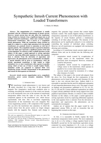
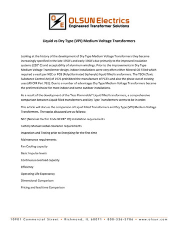
Transformers:Basics, Maintenance, and DiagnosticsA transformer has no internal moving parts, and it transfers energyfrom one circuit to another by electromagnetic induction. Externalcooling may include heat exchangers, radiators, fans, and oil pumps.Radiators and fans are evident in figure 1. The large horizontal tank atthe top is a conservator. Transformers are typically used because achange in voltage is needed. Power transformers are defined astransformers rated500 kVA and larger.Larger transformers areoil-filled for insulationand cooling; a typicalGSU transformer maycontain several thousandgallons of oil. One mustalways be aware of thepossibility of spills,leaks, fires, andenvironmental risks thisoil poses.Transformers smallerthan 500 kVA aregenerally calleddistribution transformers. Pole-top and small, pad-mountedtransformers that serve residences and small businesses are typicallydistribution transformers. Generator step-up transformers, used inReclamation powerplants, receive electrical energy at generatorvoltage and increase it to a higher voltage for transmission lines.Conversely, a step-down transformer receives energy at a highervoltage and delivers it at a lower voltage for distribution to variousloads.Figure 1 – Typical GSU Three-PhaseTransformer.All electrical devices using coils (in this case, transformers) areconstant wattage devices. This means voltage multiplied by currentmust remain constant; therefore, when voltage is “stepped-up,” thecurrent is “stepped-down” (and vice versa). Transformers transfer2
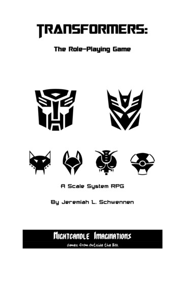
Transformers:Basics, Maintenance, and Diagnosticselectrical energy between circuits completely insulated from eachother. This makes it possible to use very high (stepped-up) voltagesfor transmission lines, resulting in a lower (stepped-down) current.Higher voltage and lower current reduce the required size and cost oftransmission lines and reduce transmission losses as well.Transformers have made possible economic delivery of electric powerover long distances.Transformers do not require as much attention as most otherequipment; however, the care and maintenance they do require isabsolutely critical. Because of their reliability, maintenance issometimes ignored, causing reduced service life and, at times, outrightfailure.2.1 Principle of OperationTransformer function is based on the principle that electrical energy istransferred efficiently by magnetic induction from one circuit toanother. When one winding of a transformer is energized from analternating current (AC) source, an alternating magnetic field isestablished in the transformer core. Alternating magnetic lines offorce, called “flux,” circulate through the core. With a second windingaround the same core, a voltage is induced by the alternating flux lines.A circuit, connected to the terminals of the second winding, results incurrent flow.Each phase of a transformer is composed of two separate coil windingswound on a common core. The low-voltage winding is placed nearestthe core; the high-voltage winding is then placed around both the lowvoltage winding and core. See figure 2 which shows internalconstruction of one phase. The core is typically made from very thinsteel laminations, each coated with insulation. By insulating betweenindividual laminations, losses are reduced. The steel core provides alow resistance path for magnetic flux. Both high- and low-voltagewindings are insulated from the core and from each other, and leads3
Transformers:Basics, Maintenance, and DiagnosticsFigure 2 – Transformer Construction.are brought out through insulating bushings. A three-phasetransformer typically has a core with three legs and has both highvoltage and low-voltage windings around each leg. Special paperand wood are used for insulation and internal structural support.2.2 Transformer ActionTransformer action depends upon magnetic lines of force (flux)mentioned above. At the instant a transformer primary is energizedwith AC, a flow of electrons (current) begins. During the instant ofswitch closing, buildup of current and magnetic field occurs. Ascurrent begins the positive portion of the sine wave, lines of magneticforce (flux) develop outward from the coil and continue to expanduntil the current is at its positive peak. The magnetic field is also at itspositive peak. The current sine wave then begins to decrease, crosseszero, and goes negative until it reaches its negative peak. Themagnetic flux switches direction and also reaches its peak in the4
Transformers:Basics, Maintenance, and Diagnosticsopposite direction. With an AC power circuit, the current changes(alternates) continually 60 times per second, which is standard in theUnited States. Other countries may use other frequencies. In Europe,50 cycles per second is common.Strength of a magnetic field depends on the amount
Introduction to Transformers Course No: E05-013 Credit: 5 PDH Elie Tawil, P.E., LEED AP 77 Cont