Transcription
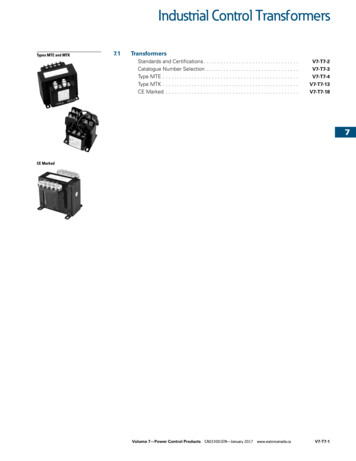
Benha UniversityFaculty of Engineering at ShubraElectrical Engineering DepartmentDr. Ahmed Mustafa HusseinChapter # 2 Transformers1. IntroductionThe transformer can change the magnitude of alternating voltage or current fromhigh to low values and vice versa. This useful property of transformer is mainlyresponsible for the widespread use of alternating currents rather than direct currentsi.e., electric power is generated, transmitted and distributed in the form of alternatingcurrent. Transformers have no moving parts, rugged and durable in construction, thusrequiring very little maintenance. They also have a very high efficiency—as high as99%. In this chapter, we shall study some of the basic properties of transformers.A transformer is a static machine. Although it is not an energy conversion device,it is essential in many energy conversion systems. It is a simple device, having two ormore electric circuits coupled by a common magnetic field. Ferromagnetic cores areused to provide tight magnetic coupling and high flux densities. Such transformers areknown as iron-core transformers. They are invariably used in high-powerapplications. Air-core transformers have poor magnetic coupling and are sometimesused in low power electronic applications.Two types of core constructions are normally used, as shown in Fig. 1. In the core type(Fig. 1a), the windings are wound around two legs of a magnetic core of rectangularshape. In the shell type (Fig. 1b), the windings are wound around the centre leg of athree-legged magnetic core.1Chapter#2 TransformersDr. Ahmed Mustafa HusseinEE3350
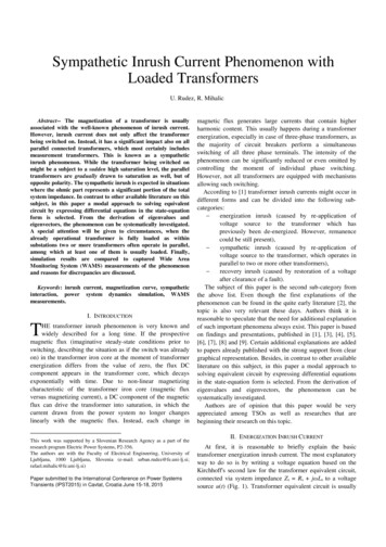
Benha UniversityFaculty of Engineering at Shubraa) Core typeElectrical Engineering DepartmentDr. Ahmed Mustafa Husseinb) Shell typeFig. 1 Core construction of single-phase transformerTo reduce core losses, the magnetic core is formed of a stack of thin laminations.Silicon-steel laminations of 0.014-inch thickness are commonly used for transformersoperating at frequencies below a few hundred cycles. L-shaped laminations are usedfor core type construction (Fig. 2a) and E-I shaped laminations are used for shell-typeconstruction (Fig. 2b).a) L-shaped laminationsb) E I-shaped laminationsFig. 2 Core laminations of single-phase transformerIn case of single-phase transformers, there two windings. One winding is connected toan AC supply and referred as primary winding. The other winding is connected to anelectrical load and referred as secondary winding. (See Fig. 3)2Chapter#2 TransformersDr. Ahmed Mustafa HusseinEE3350
Benha UniversityFaculty of Engineering at ShubraElectrical Engineering DepartmentDr. Ahmed Mustafa HusseinFig. 3 Primary and secondary windings of 1-ph transformerThe winding with the higher number of turns will have a high voltage and is called thehigh-voltage (HV) or high tension (HT) winding. The winding with the lower numberof turns is called the low-voltage (LV) or low-tension (LT) winding.To achieve tighter magnetic coupling between the windings, they may be formed ofcoils placed one on top of another (Fig. 4a) or side by side (Fig. 4b)Fig. 4 a) Coils one on anotherb) Coils side by sideIf there are more turns of wire on the primary than on the secondary, the outputvoltage will be lower than the input voltage. This is illustrated in Fig. 5 for a stepdown and a step-up transformer. Notice that the winding with the greater number ofturns has the higher voltage. In Fig. 5, one winding has twice as many turns as theother. In one case the voltage is stepped down to half, while in the other the voltage isstepped up to double.3Chapter#2 TransformersDr. Ahmed Mustafa HusseinEE3350
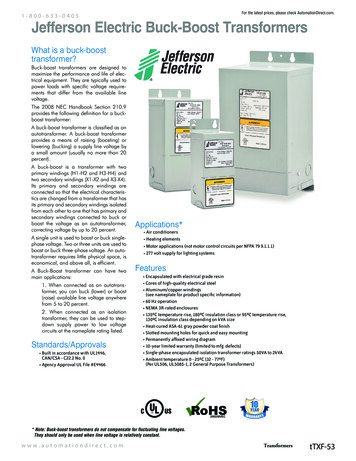
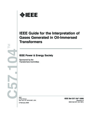
Benha UniversityFaculty of Engineering at ShubraElectrical Engineering DepartmentDr. Ahmed Mustafa HusseinFig. 5 Step- up and down transformersIt is important to know the ratio of the number of turns of wire on the primary windingas compared to the secondary winding. This is called the turns ratio of thetransformer.𝑡𝑢𝑟𝑛𝑠 𝑟𝑎𝑡𝑖𝑜 (𝑎) 𝑛𝑢𝑚𝑏𝑒𝑟 𝑜𝑓 𝑠𝑒𝑐𝑜𝑛𝑑𝑎𝑟𝑦 𝑡𝑢𝑟𝑛𝑠𝑛𝑢𝑚𝑏𝑒𝑟 𝑜𝑓 𝑝𝑟𝑖𝑚𝑎𝑟𝑦 𝑡𝑢𝑟𝑛𝑠There are different shapes for small transformers as shown in Fig. 6.single-phase TransformersThree-phase transformerFig. 6 Different shape of transformersTransformers have widespread use. Their primary function is to change voltage level.Electrical power is generated in a power station at about 30 kV. However, in domestichouses, electric power is used at 110 or 220 volts. Electric power is transmitted from apower plant to a load center at 200 to 500 kV. Transformers are used to step up andstep down voltage at various stages of power transmission, as shown in Fig. 7.4Chapter#2 TransformersDr. Ahmed Mustafa HusseinEE3350
Benha UniversityFaculty of Engineering at Shubra Electrical Engineering DepartmentDr. Ahmed Mustafa Hussein Fig. 7, Power transmission with step-up and down transformersIt is clear from the above figure that transformer #1 is step up transformer as it raisedthe voltage from 30 kV to 500 kV. But Transformers #2, #3 and #4 are step downtransformers. Therefore, based on the primary and secondary voltages, transformersare classified to:a) Step up transformers (V2 V1) (a 1)b) Step down transformers (V2 V1) (a 1)c) Isolating transformers (V2 V1) (a 1)1.1 Transformer CoolingAnother means of classifying the transformers is according to the type of coolingemployed. The following types are in common use:(a) air-blast type5Chapter#2 TransformersDr. Ahmed Mustafa HusseinEE3350
Benha UniversityFaculty of Engineering at ShubraElectrical Engineering DepartmentDr. Ahmed Mustafa Hussein(b) oil-filled self-cooled (Oil-filled transformers are built for outdoor duty)(c) oil-filled water-cooled1.2 Transformer windings:Transformer windings are constructed of solid stranded copper or aluminumconductors, but copper is the most commonly used.1.3 Transformer windings insulation:The transformer windings are insulated by insulating material. The most importantcharacteristic of the insulating material is its class. Class of insulation denotes themaximum temperature that it can withstand as shown in Fig.8. Classes A, E, B, F andH are used in dry-type transformers. For oil immersed transformers, class A is used.6Chapter#2 TransformersDr. Ahmed Mustafa HusseinEE3350
Benha UniversityFaculty of Engineering at ShubraElectrical Engineering DepartmentDr. Ahmed Mustafa HusseinFig. 8, Temperature limits according to IEC85 standard1.4 Classification of transformers (based on their function):- Power transformers: used in transmission lines and distribution systems. Theyhave the highest power (VA) ratings compared to other types. The operatingfrequency is 50 – 60 Hz.- Electronic transformers: used in electronic circuits. They are designed tooperate over a wide range of frequencies (wide-band transformers) or overspecific range of frequencies (narrow-band transformers).- Instrument transformers: used to detect voltage or current in electronic circuitsor in power systems. If they are used to detect voltage, they are called potentialtransformers. If they are used to detect current, they are called currenttransformers.- Audio and pulse transformers: used in communication circuits.1.5 Classification of transformers (based on number of windings):- Autotransformers: have one winding with electrical connection.- Conventional transformers: have 2 or more windings without electricalconnection.1.6 The following points may be noted carefully:(i) The transformer action is based on the laws of electromagnetic induction.(ii) There is no electrical connection between the primary and secondary. The ACpower is transferred from primary to secondary through magnetic flux.(iii) There is no change in frequency i.e., output power has the same frequency as theinput power.7Chapter#2 TransformersDr. Ahmed Mustafa HusseinEE3350
Benha UniversityFaculty of Engineering at ShubraElectrical Engineering DepartmentDr. Ahmed Mustafa Hussein(iv) The losses that occur in a transformer are:(a) core losses - eddy current and hysteresis losses(b) copper losses - in the resistance of the windingsIn practice, these losses are very small so that output power is nearly equal to theinput primary power. In other words, a transformer has very high efficiency.2. Ideal TransformerAlthough ideal transformer cannot be physically realized, yet its study provides a verypowerful tool in the analysis of a practical transformer. In fact, practical transformershave properties that approach very close to an ideal transformer.Consider a transformer with two windings, a primary winding of N1 turns and asecondary winding of N2 turns, as shown schematically in Fig. 9. Ideal transformer hasthe following properties: The winding resistances are negligible. All fluxes are confined to the core and link both windings; that is, no leakagefluxes are present. Permeability of the core is infinite. The core losses (hysteresis & eddy) are negligible.Fig. 9, Ideal transformerWhen the primary winding is connected to a time-varying voltage v1, a time-varyingflux Φ is established in the core. A voltage e1 will be induced in the winding and willequal the applied voltage if resistance of the winding is neglected:8Chapter#2 TransformersDr. Ahmed Mustafa HusseinEE3350
Benha UniversityFaculty of Engineering at ShubraElectrical Engineering DepartmentDr. Ahmed Mustafa HusseinThe core flux also links the secondary winding and induces a voltage e2, which is thesame as the terminal voltage v2:From the above two equations:𝑉2 𝑁2 𝑎𝑉1 𝑁1where a is the turns ratio.Let us now connect a load (by closing the switch in Fig. 9) to the secondary winding.A current i2 will flow in the secondary winding, and the secondary winding willprovide an mmf N2i2 for the core. This will immediately make a primary windingcurrent i1 flow so that a counter-mmf N1i1 can oppose N2i2.𝐼2 𝑁1 1 𝐼1 𝑁2 𝑎2.1 Phasor diagram of ideal transformer (at no load)Consider an ideal transformer on no load i.e., secondary is open-circuited as shown inFig. (10 (i)). Under such conditions, the primary is simply a coil of pure inductance.When an alternating voltage V1 is applied to the primary, it draws a small magnetizingcurrent Im which lags the applied voltage by 90 . This alternating current Im producesan alternating flux which is proportional to and in phase with it. The alternating flux links both the windings and induces e.m.f. E1 in the primary and e.m.f. E2 in thesecondary. The primary e.m.f. E1 is, at every instant, equal to and in opposition to V1(Lenz’s law). Both e.m.f.s E1 and E2 lag behind flux by 90 . However, theirmagnitudes depend upon the number of primary and secondary turns. Fig. (10 (ii))shows the phasor diagram of an ideal transformer on no load. Since flux is commonto both the windings, it has been taken as the reference phasor.9Chapter#2 TransformersDr. Ahmed Mustafa HusseinEE3350
Benha UniversityFaculty of Engineering at ShubraElectrical Engineering DepartmentDr. Ahmed Mustafa Hussein(i) Transformer circuit(ii) Phasor diagramFig. 10 Ideal transformer at no load2.2 E.M.F. Equation of a transformerConsider that an alternating voltage V1 of frequency f is applied to the primary asshown in Fig. (10 (i)). The sinusoidal flux produced by the primary can berepresented as:The instantaneous e.m.f. e1 induced in the primary isThe maximum value of induced e.m.f. in the primary is Em1:The r.m.s. value E1 of the primary e.m.f. isSimilarlyExample (1):A single-phase transformer has 400 primary and 1000 secondary turns. The net crosssectional area of the core is 60 cm2. If the primary winding be connected to a 50-Hzsupply at 520 V, calculate (i) the peak value of flux density in the core (ii) the voltageinduced in the secondary winding.a N2/N1 1000/400 2.510Chapter#2 TransformersDr. Ahmed Mustafa HusseinEE3350
Benha UniversityFaculty of Engineering at ShubraElectrical Engineering DepartmentDr. Ahmed Mustafa Hussein(i) E1 4.44 f N1 Bm Aor 520 4.44 50 400 Bm (60 10 4) Bm 0.976 Wb/m2(ii) E2/E1 a Ε2 a Ε1 2.5 520 1300 VExample (2):A 25-kVA transformer has 500 turns on the primary and 50 turns on the secondarywinding. The primary is connected to 3000-V, 50-Hz supply. Find the full-loadprimary and secondary currents, the secondary e.m.f. and the maximum flux in thecore. Neglect leakage drops and no-load primary current.a N2/N1 50/500 0.1Now, full-load I1 25,000/3000 8.33 A.F.L. I2 I1/a 10 8.33 83.3 AE2 aE1 3000 0.1 300 VAlso, E1 4.44 f N1Φm; 3000 4.44 50 500 Φm Φm 27 mWb2.2 Polarity of Transformer WindingsWindings of transformers or other electrical machines are marked to indicate terminalsof like polarity. Consider the two windings shown in Fig. 11. Terminals 1 and 3 areidentical, if the currents entering these terminals produce fluxes in the same directionin the core that forms the common magnetic path. For the same reason, terminals 2and 4 are identical. If these two windings are linked by a common time-varying flux,voltages will be induced in these windings such that if at a particular instant thepotential of terminal 1 is positive with respect to terminal 2, then at the same instantthe potential of terminal 3 will be positive with respect to terminal 4.Fig. 11, Polarity of transformer windings11Chapter#2 TransformersDr. Ahmed Mustafa HusseinEE3350
Benha UniversityFaculty of Engineering at ShubraElectrical Engineering DepartmentDr. Ahmed Mustafa HusseinPolarities of windings must be known if transformers are connected in parallel to sharea common load as shown in Fig. 12.a) Correct connectionb) Wrong connectionFig. 12 Parallel connection of transformersThe relation between primary voltage and current with the secondary voltage andcurrent is related by the dot notation as follows: If V1 and V2 are both either positive or negative at the dotted terminals, usepositive turns ratio, otherwise use negative turns ratio. If I1 and I2 both enter into or both leave the dotted terminals, use negative turnsratio, otherwise use positive turns ratio.Figure 13 explains the above rules:Fig. 13 Turns ratio sign12Chapter#2 TransformersDr. Ahmed Mustafa HusseinEE3350
Benha UniversityFaculty of Engineering at ShubraElectrical Engineering DepartmentDr. Ahmed Mustafa Hussein3. Shifting Impedances in a TransformerConsider the transformer circuit shown in Fig. 14, then the ratio between the primaryimpedance Z1 and the secondary impedance Z2 that is Z2/Z1 is square of turns ratio as:Fig. 14 Transformer CircuitNote the importance of above relations. We can transfer the parameters from onewinding to the other. Thus:(i) A resistance R1 in the primary becomes a2 R1 when transferred to the secondary.(ii) A resistance R2 in the secondary becomes R2/a2 when transferred to the primary.(iii) A reactance X1 in the primary becomes a2 X1 when transferred to the secondary.(iv)A reactance X2 in the secondary becomes X2/ a2 when transferred to theprimary.(v) When transferring voltage or current from one winding to another, only a is used.Example (3):A single-phase power system consists of a 480-V, 60-Hz generator supplying a loadZload 4 j3.0 Ω through a transmission line of impedance Zline 0.18 j0.24 Ω.a) If no transformers are used, what will the voltage at the load be? What will thetransmission line losses be?b) If T1 and T2 transformers are used, what will the voltage at the load be? What will thetransmission line losses be?13Chapter#2 TransformersDr. Ahmed Mustafa HusseinEE3350
Benha UniversityFaculty of Engineering at ShubraElectrical Engineering DepartmentDr. Ahmed Mustafa Husseina) If there no transformers are used:𝐼𝐺 𝐼𝑙𝑖𝑛𝑒 𝐼𝑙𝑜𝑎𝑑 480 90.7601 37.78 𝐴(4 0.18) 𝑗(3 0.24)Vload Iload Zload 90.7601 -37.78 (4 j3) 453.8005 -0.9101 VLosses at transmission line Iline2 (Rline) (90.7601)2 0.18 1482.7312 Wb) If the two transformers are used:Refer Zload from the secondary of T2 to the primary of T2:′𝑍𝑙𝑜𝑎𝑑10 2 (4 𝑗3) ( ) 400 𝑗300 𝑜ℎ𝑚1Zload’ is connected in series with ZlineZtot 400.18 300.24 ΩRefer Ztot from the secondary of T1 to the primary of T1:′𝑍𝑡𝑜𝑡1 2 (400.18 𝑗300.24) ( ) 4.0018 𝑗3.0024 𝑜ℎ𝑚10480𝐼𝐺 95.9447 36.8795 𝐴(4.0018) 𝑗(3.0024)𝐼𝑙𝑖𝑛𝑒 𝐼𝐺 1 9.59447 36.8795 𝐴10Losses at transmission line Iline2 (Rline) (9.59447)2 0.18 16.5698 W14Chapter#2 TransformersDr. Ahmed Mustafa HusseinEE3350
Benha UniversityFaculty of Engineering at Shubra𝐼𝑙𝑜𝑎𝑑 𝐼𝑙𝑖𝑛𝑒 Electrical Engineering DepartmentDr. Ahmed Mustafa Hussein10 95.9447 36.8795 𝐴1Vload Iload Zload 95.9447 -36.8795 (4 j3) 479.7235 -0.0096 VNotice that raising the transmission voltage of the power system reduced transmissionlosses by 98.88%.4. Practical Transformerin a practical transformer the windings have resistances, not all windings link the sameflux, permeability of the core material is not infinite, and core losses occur when thecore material is subjected to time-varying flux. In the analysis of a practicaltransformer, all these imperfections must be considered.A practical transformer differs from the ideal transformer in many respects. Thepractical transformer has(i)iron losses(ii) winding resistances and(iii) magnetic leakage,Iron losses: Since the iron core is subjected to alternating flux, there occurs eddycurrent and hysteresis loss in it. These two losses together are known as iron losses orcore losses. The iron losses depend upon the supply frequency, maximum flux densityin the core, volume of the core etc. It may be noted that magnitude of iron losses isquite small in a practical transformer.Winding resistances: Since the windings consist of copper conductors, it immediatelyfollows that both primary and secondary will have winding resistance. The primaryresistance R1 and secondary resistance R2 act in series with the respective windings asshown in Fig. 10. When current flows through the windings, there will be power lossas well as a loss in voltage due to I R drop. This will affect the power factor and E1will be less than V1 while V2 will be less than E2.Leakage reactances: Both primary and secondary currents produce flux. The flux m which links both the windings is the useful flux and is called mutual flux (as shownin Fig. 14). However, primary current would produce some flux l1 which would not15Chapter#2 TransformersDr. Ahmed Mustafa HusseinEE3350
Benha UniversityFaculty of Engineering at ShubraElectrical Engineering DepartmentDr. Ahmed Mustafa Husseinlink the secondary winding. Similarly, secondary current would produce some flux l2 that would not link the primary winding. The flux such as l1 or l2 which links onlyone winding is called leakage flux. The leakage flux paths are mainly through the air.In other words, the effect of primary leakage flux l1 is to introduce an inductivereactance X1 in series with the primary winding. Similarly, the secondary leakage flux l2 introduces an inductive reactance X2 in series with the secondary winding. Therewill be no power loss due to leakage reactance. However, the presence of leakagereactance in the windings changes the power factor as well as there is voltage loss dueto IX drop.In a practical magnetic core having finite permeability, a magnetizing current I m isrequired to establish a flux in the core. This effect can be represented by a magnetizingreactance Xm. Also, the core loss in the magnetic material can be represented by aresistance Rc.Fig. 14 Practical transformerR1 is the primary-winding resistance,X1 is the primary-winding leakage reactance,R2 is the secondary-winding resistance,16Chapter#2 TransformersDr. Ahmed Mustafa HusseinEE3350
Benha UniversityFaculty of Engineering at ShubraElectrical Engineering DepartmentDr. Ahmed Mustafa HusseinX2 is the secondary-winding leakage reactance,Rc is the core loss resistance,Xm is the magnetizing reactanceThe parallel branches Rc and Xm represent the no-load circuit. Also the phasor sum ofboth Im and Ic gives the no-load current I .4.1 Exact Equivalent CircuitsThe transformer circuit can be moved to the right or left by referring all quantities tothe primary or secondary side, respectively. This is almost invariably done. Theequivalent circuit moved to primary is shown in Fig. 15 below.Fig. 15 Exact equivalent circuit referred to primary sideIf we shift all the impedances from one winding to the other, the transformer core iseliminated and we get an equivalent electrical circuit. Various voltages and currentscan be readily obtained by solving this electrical circuit.4.2 Approximate Equivalent CircuitsThe voltage drops I1R1 and I1Xl1 (Fig. 14) are normally small and E1 V1 . If thisis true, then the shunt branch (composed of Rc and Xm) can be moved to the supplyterminal, as shown in Fig. 16. This approximate equivalent circuit simplifiescomputation of currents.17Chapter#2 TransformersDr. Ahmed Mustafa HusseinEE3350
Benha UniversityFaculty of Engineering at ShubraElectrical Engineering DepartmentDr. Ahmed Mustafa HusseinFig. 16 Approximate equivalent circuit referred to primary side4.3 More Approximate Equivalent CircuitsGenerally, the exciting current I is a small percentage of the rated current of thetransformer (less than 5%). A further approximation of the equivalent circuit can bemade by removing the excitation branch, as shown in Fig. 17.Fig. 17 More approximate equivalent circuit referred to primary side4.4 Phasor Diagrams of Practical Transformer:We shall consider two cases:(i)when the winding resistance and leakage flux are neglected,(ii)when the winding resistance and leakage flux are considered.when the winding resistance and leakage flux are neglectedIn case of transformer at no load, the phasor diagram is shown in Fig. 18: The flux ( ) is considered as a reference on horizontal axis, and the induced voltageof the primary (E1) and secondary (E2) are lagging this flux by 90 18Chapter#2 TransformersDr. Ahmed Mustafa HusseinEE3350
Benha UniversityFaculty of Engineering at ShubraElectrical Engineering DepartmentDr. Ahmed Mustafa Hussein The reactive component of current (Im) is small in amount and in the same directionof the flux and lag the supply voltage (V1) by 90 𝐼𝑚 𝐼Φ sin (𝜙𝑜 ) The active component of current (Ic) which is in the same direction of the supplyvoltage (V1)𝐼𝑐 𝐼Φ cos (𝜙𝑜 )Fig. 18 Phasor diagram at no loadIn case of inductive load which causes the secondary current I2 to lag the secondaryvoltage V2 by 2. The total primary current I1 must meet two requirements: (a) It mustsupply the no-load current I to meet the iron losses in the transformer and to provideflux in the core. (b) It must supply a current I'2 to counteract the demagnetizing effectof secondary currently I2. The magnitude of I'2 will be a I2 and 180 out of phase asshown in Fig. 19.Fig. 19 Phasor diagram when R and X are neglected19Chapter#2 TransformersDr. Ahmed Mustafa HusseinEE3350
Benha UniversityFaculty of Engineering at ShubraElectrical Engineering DepartmentDr. Ahmed Mustafa HusseinExample:(a) A 2,200/200-V transformer draws a no-load primary current of 0.6 A and absorbs400 watts. Find the magnetising and iron loss currents. (neglect winding resistancesand leakage reactances)Iron-loss current Ic 400/2200 0.182 AAs we know, 𝐼 𝐼𝑐 2 𝐼𝑚 2 OR 𝐼𝑚 𝐼 2 𝐼𝑐 2𝐼𝑚 0.62 0.1822 𝟎. 𝟓𝟕𝟐 𝑨(b) A 2,200/250-V transformer takes 0.5 A at a p.f. of 0.3 on open circuit. Findmagnetising and working components of no-load primary current. (neglect windingresistances and leakage reactances)𝜙𝑜 𝑐𝑜𝑠 1 0.3 72.542𝐼𝑚 𝐼Φ sin(𝜙𝑜 ) 0.5 sin(72.542) 𝟎. 𝟒𝟕𝟕 𝑨𝐼𝑐 𝐼Φ cos(𝜙𝑜 ) 0.5 0.3 𝟎. 𝟏𝟓 𝑨Example:A single-phase transformer has 1000 turns on the primary and 200 turns on thesecondary. The no load current is 3 A, at a p.f. of 0.2 lag. Calculate the primarycurrent and power-factor when the secondary current is 280 A at a p.f. of 0.80 lagging.(neglect winding resistances and leakage reactances)Taking the primary voltage V1 as a reference.Turns ration (a) 200/1000 0.2Secondary power factor 0.8 lag 2 - 36.87 (wrt V2)I2 280 -(180 36.87) A (wrt V1)I2’ 280 0.2 56 -36.87 ANo-load power factor 0.2 lag o - 78.463 (wrt V1)I 3 -78.463 AI1 56 -36.87 3 -78.463 58.278 -38.828 APrimary power factor cos (38.828) 0.779 lag20Chapter#2 TransformersDr. Ahmed Mustafa HusseinEE3350
Benha UniversityFaculty of Engineering at ShubraElectrical Engineering DepartmentDr. Ahmed Mustafa HusseinExample:A transformer has a primary winding of 800 turns and a secondary winding of 200turns. When the load current on the secondary is 80 A at 0.8 power factor lagging, theprimary current is 25 A at 0.707 power factor lagging. Determine the no-load currentof the transformer and its phase with respect to primary voltage.Turns ration (a) 200/800 0.25I2’ 80 0.25 20 -36.9 AI 25 -45 - 20 -36.9 5.914 -73.457 AExample:The primary of a certain transformer takes 1 A at a power factor of 0.4 when it isconnected across a 200-V, 50-Hz supply and the secondary is on open circuit. Thenumber of turns on the primary is twice that on the secondary. A load taking 50 A at alagging power factor of 0.8 is now connected across the secondary. What is the valueof primary current and its power factor?21Chapter#2 TransformersDr. Ahmed Mustafa HusseinEE3350
Benha UniversityFaculty of Engineering at ShubraElectrical Engineering DepartmentDr. Ahmed Mustafa HusseinTurns ration (a) N2 / N1 0.5I2’ 50 0.5 25 -36.9 AI 1 -66.422I1 25 -36.9 1 -66.422 25.8749 -37.9912 APrimary power factor cos (37.9912) 0.7881 lag.when the winding resistance and leakage flux are consideredThis is the actual conditions that exist in a transformer. There is voltage drop inR1 and X1 so that primary e.m.f. E1 is less than the applied voltage V1. Similarly, thereis voltage drop in R2 and X2 so that secondary terminal voltage V2 is less than thesecondary e.m.f. E2.Let us take the usual case of inductive load which causes the secondary current I2 tolag behind the secondary voltage V2 by 2. The total primary current I1 will be thephasor sum of I'2 and I i.e.,𝐼1 𝐼 𝐼2 ′The above equations are represented by phasor diagram shown in Fig. 20.22Chapter#2 TransformersDr. Ahmed Mustafa HusseinEE3350
Benha UniversityFaculty of Engineering at ShubraElectrical Engineering DepartmentDr. Ahmed Mustafa HusseinFig. 20 Phasor diagram when R and X are considered (Inductive load)Note that counter e.m.f. that opposes the applied voltage V1 is E1. Therefore, if weadd I1R1 (in phase with I1) and I1 X1 (90 ahead of I1) to E1, we get the appliedprimary voltage V1. The phasor E2 represents the induced e.m.f. in the secondary bythe mutual flux . The secondary terminal voltage V2 will be what is left over aftersubtracting I2R2 and I2X2 from E2.Now, we need to draw the phasor diagram at unity power factor. The only differenceis that the angle ( 2) between the load voltage V2 and the load current I2 become zeroas shown in Fig. 2123Chapter#2 TransformersDr. Ahmed Mustafa HusseinEE3350
Benha UniversityFaculty of Engineering at ShubraElectrical Engineering DepartmentDr. Ahmed Mustafa HusseinFig. 21 Phasor diagram when R and X are considered (Resistive load)If we need to draw the phasor diagram at leading power factor. The only difference isthat the load current I2 is leading the load voltage V2 by angle ( 2) as shown in Fig. 22Fig. 22 Phasor diagram when R and X are considered (Capacitive load)Example:A 100 kVA, 1100/220 V, 50 Hz, single-phase transformer has a leakage impedance of(0.1 J0.4) ohm for the H.V. winding and (0.006 J0.015) ohm for the L.V. winding.24Chapter#2 TransformersDr. Ahmed Mustafa HusseinEE3350
Benha UniversityFaculty of Engineering at ShubraElectrical Engineering DepartmentDr. Ahmed Mustafa HusseinFind the equivalent winding resistance, reactance and impedance referred to the H.V.and L.V. sides.Turns ratio (N2/N1) (V2/ V1) 220/1100 0.2(i) Referred to H.V. side (Primary):Resistance r1 r2’ 0.1 [0.006 (1100/220)2] 0.25 ΩReactance x1 x2′ 0.4 [0.015 (1100/220)2] 0.775 ΩImpedance (0.252 0.7752)0.5 0.8143 Ω(ii) Referred to L.V. side (Secondary):Resistance r2 r1’ 0.006 [0.1 (0.2)2] 0.01 ΩReactance x2 x1′ 0.015 [0.4 (0.2)2] 0.031 ΩImpedance (0.012 0.0312)0.5 0.0328 ΩExample:The following data refer to a single-phase transformer:Turn ratio N2:N1 1:19.5; R1 25 Ω; X1 100 Ω; R2 0.06 Ω; X2 0.25 Ω. No-loadcurrent 1.25 A leading the flux by 30 . The secondary delivers 200 A at a terminalvoltage of 500 V and p.f. of 0.8 lagging. Determine by the aid of a phasor diagram, theprimary voltage, and primary p.f.Assuming V2 as reference vector, V2 500 0I2 200 -36.87 AE2 500 0 200 -36.87 (0.06 j0.25) 540.596 3.479 VNow assuming the horizontal axis is taken as a reference vector,E1 540.596 19.5 10541.622 90 VI2’ 200/19.5 10.2564 (180-90-36.87-3.479) 10.2564 49.651 AI1 1.25 30 10.2564 49.651 11.4413 47.5454 AV1 10541.622 90 11.4413 47.5454 (25 j100) 11543.3325 93.2333 VThe angle between V1 and I1 93.2333 – 47.5454 45.6879Primary power factor cos(45.6879) 0.6986 lag25Chapter#2 TransformersDr. Ahmed Mustafa HusseinEE3350
Benha UniversityFaculty of Engineering at ShubraElectrical Engineering DepartmentDr. Ahmed Mustafa HusseinExample:The parameters of a 2300/230 V, 50-Hz transformer are given below:R1 0.286 ΩR2′ 0.319 ΩX1 0.73 ΩX2′ 0.73 ΩRc 250 ΩXm 1250 ΩThe load impedance ZL 0.387 j 0.29 Ω.Based on exact equivalent circuit with normal voltage across the primary, calculate:a) The primary current,b) Primary power factorc) The load current referred to primary,d) The iron loss,e) Efficiency.a 230/2300 0.1;ZL 0.387 j 0.29 Ω26Chapter#2 TransformersDr. Ahmed Mustafa HusseinEE3350
Benha UniversityFaculty of Engineering at ShubraElectrical Engineering DepartmentDr. Ahmed Mustafa HusseinZL′ ZL/a2 100 (0.387 j 0.29)
Electrical Engineering Department Dr. Ahmed Mustafa Hussein Benha University Faculty of Engineering at Shubra 1 Chapter#2 Transformers Dr. Ahmed Mustafa Hussein EE3350 Chapter # 2 Transformers 1. Introduction The transformer can change