Transcription
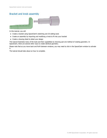
SpaceClaim tutorial: knob and bracketBracket and knob assemblyIn this tutorial, you will: Create a bracket using SpaceClaim's sketching and 3D editing tools Create an assembly by importing and modifying a knob to fit into your bracket Create a drawing sheet to detail your designThis tutorial illustrates many of the tools and their capabilities by showing just one method of creating geometry. InSpaceClaim, there are several other ways to create identical geometry.Please note that as you move back and forth between windows, you may need to click in the SpaceClaim window to activateit.The tutorial should take about an hour to complete. 2009 SpaceClaim Corporation. All rights reserved.
SpaceClaim tutorial: knob and bracketBracket and knob tutorial: Step 1Create a new design document1.Select New New Design from the Application menuto create a new design.A blank design containing the sketch grid is displayed in a new Design window. The mode is set to Sketch, sincethat is usually the first step to create a new design.The following figure shows some of the interface elements referred to in this tutorial.2.Select Save from the Application menu to name and save your design.The name of your design appears as the top-level component in the Structure tree. 2009 SpaceClaim Corporation. All rights reserved.1
SpaceClaim tutorial: knob and bracketBracket and knob tutorial: Step 2Spin, pan, and zoom1.2.2Experiment with the various methods for orienting the view: Use the middle mouse button. (Drag the middle mouse button to spin, Shift drag to pan, and Ctrl drag it tozoom based on cursor position.) Use the Spin, Pan, and Zoom tools in the Orient ribbon group. Use the Spin, Pan, and Zoom tools at the bottom right of the SpaceClaim window. Use a Spaceball (optional).Click Home in the Orient ribbon group or press the H key to restore the original view. 2009 SpaceClaim Corporation. All rights reserved.
SpaceClaim tutorial: knob and bracketBracket and knob tutorial: Step 3Set your design preferences1.Click SpaceClaim Options in the Application menu2.Click Units.3.Select Imperial from the Type drop-down.Inches appear in the Length drop-down, the minor grid spacing changes from .1mm to 1/8 in, and the minor gridlines per major changes from 10 to 8. This means that you can dimension in inches, and that the sketch gridlines are now spaced 1/8 inch apart, and the darker grid lines appear every inch.4.Select Decimal from the Decimal/fraction drop-down.5.Click OK. 2009 SpaceClaim Corporation. All rights reserved.3
SpaceClaim tutorial: knob and bracketBracket and knob tutorial: Step 4Create the bottom of the bracket1.Sketch a rectangle that will become the bottom piece of the bracket.2.Click the Rectangle toolin the Sketch ribbon group on the Design tab.The grid indicates that you are in Sketch mode.Note that pressing the K key is a shortcut for quickly returning to Sketch mode.3.Click to set the first corner of the rectangle. (Start at the upper left.)As you move your mouse, a preview of the rectangle is drawn, and dimension fields appear.4.Type 1.125, then press Tab and dimension the second side by typing 4.281.5.Press Enter to complete the rectangle.Note: If you make a mistake, click a dimension to edit it, or click the Select toolin the Edit ribbongroup and double-click the rectangle to select it. Then press Delete to delete the rectangle and redraw it.You can also use Ctrl Z and Ctrl Y to undo and redo steps.2.Pull the rectangle into 3D to create the bottom of the bracket.1.Switch to 3D mode by clicking the 3D mode toolin the Mode ribbon group.You can also use the D key to quickly enter 3D mode.The Pull toolin the Edit ribbon group is activated, your sketched rectangle now appears as arectangular surface, and the surface appears in the Structure tree.2.Click on the rectangular surface to select it.The faint yellow cursor arrows show you the directions in which you can pull the rectangle.3.4Drag to begin adding thickness to the rectangle. 2009 SpaceClaim Corporation. All rights reserved.
SpaceClaim tutorial: knob and bracketYou can drag with your cursor anywhere in the Design window—you do not have to drag on the Pull arrowitself. We recommend that you move your mouse off to the side when pulling to make it easier to see yourchanges.4.Type .483 and press Enter.The surface in the Structure tree becomes a solid. (Pulling a curve creates a surface, while pulling a surfacecreates a solid.)3.Press Ctrl S or select Save from the Application menu 2009 SpaceClaim Corporation. All rights reserved.to save your design.5
SpaceClaim tutorial: knob and bracketBracket and knob tutorial: Step 5Create the back of the bracket1.Extrude an edge to form a surface.1.Click the back edge of the solid with the Pull tool to select it.The edge is highlighted and edge options appear in the Options panel and mini-toolbar. Move your mousecloser to the mini-toolbar to make it more opaque.If you moved the model in the Design window, click the Home button in the Orient group on the Designtab. You can also press H. This orients the model to its default view and sizes it to fit inside the Designwindow, as shown in the images.2.Select the extrude edge optionin the Options panel.(You can hover over any option to display a tooltip that explains the option.)The Pull arrows change to indicate the two default directions in which you can extrude the edge.3.Drag the edge upward to begin creating a surface.4.While dragging, press and release the spacebar to display a dimension field.You can press the spacebar to edit a dimension whenever a dimension is displayed.5.Type 1.4.6.Press Enter to complete the surface.This surface now appears in the structure tree, below the solid.2.Pull the surface into a solid.1.6Click the surface you just created and drag toward the front of the solid as shown below. 2009 SpaceClaim Corporation. All rights reserved.
SpaceClaim tutorial: knob and bracket2.Enter .483 to match the thickness of your first solid.3.Press Enter to finish pulling and create the surface.In the Structure tree, the surface disappears and this new solid is automatically merged with the first.3.Save your work. 2009 SpaceClaim Corporation. All rights reserved.7
SpaceClaim tutorial: knob and bracketBracket and knob tutorial: Step 6Round the corners1.2.Round the inside corner of the bracket.1.Click the edge on the inside corner of the bracket with the Pull tool.2.Select the Round Edge pull option3.Drag in the direction of the arrow to round the edge.4.While dragging, press and release the spacebar to display a dimension field.5.Type .2 and press Enter.in the mini-toolbar and the Options panel.Round the outside corner of the bracket.1.Turn the bracket so you can see the bottom by clicking the Spin tooldragging to spin your design.in the Orient ribbon group andAnother way to spin is to mouse over an edge in your design, then press Alt and drag with the middlemouse button to spin your design around that edge.(Release the Alt key after you start spinning the model.)Spinning in this way lets you keep the current tool active.2.8Repeat the previous steps to create a 0.4" round on the outer edge, as shown below. 2009 SpaceClaim Corporation. All rights reserved.
SpaceClaim tutorial: knob and bracket3.3.Click Homein the Orient ribbon group to return the design to trimetric view.Save your work. 2009 SpaceClaim Corporation. All rights reserved.9
SpaceClaim tutorial: knob and bracketBracket and knob tutorial: Step 7Taper the end of the bracket (Part 1)1.Sketch a dimensioned point on the top face of the long arm of the bracket, as shown in the figure.1.Click the Select toolin the Edit ribbon group and select the top face of the bottom piece of the bracket.Note that pressing the Esc key several times returns you to the Select tool.2.Click the Point toolin the Sketch ribbon group.You are now in Sketch mode. The sketch grid appears and the Sketch mode toolis active in the Moderibbon group. Because you entered Sketch mode with a face selected, SpaceClaim assumes you want tosketch on that face, and orients the sketch grid along that face.3.ClickPlan View in the Orient ribbon or the mini-toolbar to view the sketch grid head-on.4.Place the cursor over the bottom right vertex of the face (as shown below) and press and release Shift,then move your mouse toward the back of the bracket along the right edge without pressing any mousebutton. A dimension field appears.This method (often called "Shift touch" dimensioning) allows any object in any tool to dimension from thatreferenced object.5.Press and release the spacebar to dimension the point’s distance from the vertex (1.5" along the edge).Press Tab if you need to switch dimension fields.6.Press Enter to create the point.If the point was created at the wrong place, you can press Ctrl Z or clickthe left side of the SpaceClaim title bar) to try again.2.in the Quick Access toolbar (onDraw an angled line.1.Click the Line toolin the Sketch ribbon group.You can use the L key as a shortcut to the Line tool.2.Click the point you created in the previous step (a small green ball appears when the cursor is over thepoint) and then move the cursor to create a line similar to the image (edges will highlight when the cursor isover them to indicate coincidence).Two dimensions appear, one for the line's length and one for the angle formed between the sketch grid andthe line.3.10Press and release the spacebar to dimension the line. Using the Tab key, switch to the angle dimension and 2009 SpaceClaim Corporation. All rights reserved.
SpaceClaim tutorial: knob and brackettype 103 to change the angle of the line.4.Press the Esc key to end line creation.You can also right-click and select Finish Line.3.Remove material from the bracket.1.Go to Home view and press P to enter the Pull tool.You are now back in 3D mode. The 3D mode tool2.is active in the Mode ribbon group.Click the triangular region created by the line and the edge of the bracket.Note that the line effectively splits the original surface into two surfaces.3.Drag downward until all the material is removed.Note that as you pull, the Pull tool assumes that you want to remove material, and the cursor changes toindicate that the pull is subtractive. If you pull in the opposite direction, material will be added.4.Save your work. 2009 SpaceClaim Corporation. All rights reserved.11
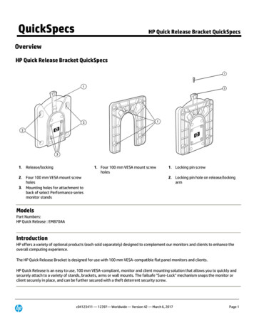
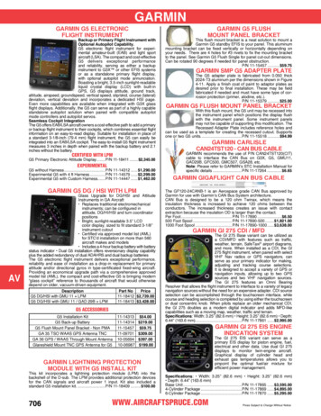
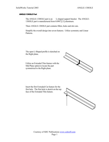
SpaceClaim tutorial: knob and bracketBracket and knob tutorial: Step 8Taper the end of the bracket (Part 2)1.Copy the existing edge to use as a pivot axis.1.Use the Views drop-down menu to select the Isometric view, then rotate the model to view the other side(see figure).2.Select the bottom left edge of the bracket, as shown below. img 3.In the Options panel or the mini-toolbar, select the Copy Edgeoption.Two arrows appear to indicate the directions the edge can be copied along existing surfaces. You can Tabbetween the directions.4.Drag the edge along the surface 1.5". img 2.Revolve the face to match the angled face on the other side of the bracket.1.Select the newly created surface between the new line and the end of the bracket. img 122.Click the Revolve tool guide(located on the right side of the Design window).3.Click the line created in the previous step. 2009 SpaceClaim Corporation. All rights reserved.
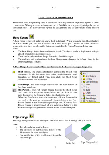
SpaceClaim tutorial: knob and bracket img The line is highlighted in blue and the Pull arrow changes to show that pulling will revolve the selected face.3.4.Drag to begin revolving the face. While dragging, press and release the spacebar to dimension the revolve.5.Enter -13 and press Enter to finish the revolve.Save your work. 2009 SpaceClaim Corporation. All rights reserved.13
SpaceClaim tutorial: knob and bracketBracket and knob tutorial: Step 9Round the tapered end1.Clear your previous selections by clicking in white space in the Design window.This method ensures that you stay within the same tool (Pull in this example).2.Select one of the edges at the end of the bracket and Ctrl click the other edge to add it to your selection.3.Click the4.Create a full round on the end of the bracket:5.14Round option in the Options panel or the mini-toolbar.1.Drag in the direction of the arrow until both edges are slightly rounded.2.Slowly pull the mouse back as if you were removing the round.1.Keep going until the end is fully rounded.Save your work. 2009 SpaceClaim Corporation. All rights reserved.
SpaceClaim tutorial: knob and bracketBracket and knob tutorial: Step 10Create a hole1.Create a circle at the end of the bracket.1.Click the Circle toolbracket.in the Sketch ribbon group and then click the top surface of the long arm of the2.ClickPlan View in the Orient ribbon group or the Plan View icon in the toolbar at the bottom of the gridto view the sketch grid head-on.3.The center of the arc created by the full round is shown with a cross.4.Click the center of the arc and move the cursor to begin sketching a circle, then use the spacebar todimension the diameter to 0.3".5.2.3.Pull the circle to create a hole in the end of the bracket.1.Click the Pull toolin the Edit ribbon group and go to Home view.2.Select the circular region and drag downward until all the material is removed.3.Drag with the middle mouse button to spin the bracket so you can see through the hole.Save your work. 2009 SpaceClaim Corporation. All rights reserved.15
SpaceClaim tutorial: knob and bracketBracket and knob tutorial: Step 11Create a second hole1.Copy the existing hole.1.Select the cylindrical inner surface of the hole.2.Click the Move tool from the Edit ribbon group.3.While holding down the Ctrl key, select and drag the arrow (vector) in the Move handle.The hole is copied along the arm of the bracket. You can see previews of the hole as long as the geometry isvalid.4.2.Stop dragging anywhere to complete the copy.Position the hole accurately.1.Click on the same arrow or vector in the Move handle.2.In the small toolbar that appears, click theRuler Dimension tool.A dimension will appear and snap to geometry as you hover over various entities.3.Select the point created earlier or either of the edges that are coincident with it.The dimension freezes and waits for a new value to be entered.16 2009 SpaceClaim Corporation. All rights reserved.
SpaceClaim tutorial: knob and bracket4.Enter a value of zero to align the axis of the hole with these edges.You can also offset selected geometry from a reference by entering a value using the same method.3.4.Increase the size of the hole.1.Press P to select the Pull tool and select the cylindrical surface of the hole.2.Drag in the opposite direction of the arrow to increase the size of the hole to a dimension of your choice.3.Use Ctrl Z to undo the previous operation and return the hole to its original size. If you go too far, useCtrl Y to redo steps.Save your work. 2009 SpaceClaim Corporation. All rights reserved.17
SpaceClaim tutorial: knob and bracketBracket and knob tutorial: Step 12Create a pattern of holes1.Create a pattern with the Move tool.1.Press M to select the Move tool.2.Check the Create Patterns option in the Options panel.3.Zoom into your design by selecting Zoom Extents from the Zoom tool menu to make the next step easier.4.Click the inner cylindrical surface of the hole that you just created.5.Press and hold the Ctrl key while dragging the Move handle along the long axis of the bracket a distance of1.7".You can release the Ctrl key after you begin dragging.A pattern count parameter is displayed, along with the dimension from the original hole to the copied hole.2.Edit the pattern.1.Use the Tab key to highlight the count entry and enter a value of 4.Four identical, equidistant holes appear on the bracket surface. These holes are now part of a pattern. Thedimension between each hole in the pattern is now displayed as well as the other parameters.2.Select the Pull tool and select an axis of one of your holes.3.4.18Drag to change the holes to slots. 2009 SpaceClaim Corporation. All rights reserved.
SpaceClaim tutorial: knob and bracketNotice that changes made to one hole affect all the others in the pattern.5.3.Press Ctrl Z to undo your change.Save your work. 2009 SpaceClaim Corporation. All rights reserved.19
SpaceClaim tutorial: knob and bracketBracket and knob tutorial: Step 13Chamfer the top edge1.Chamfer the top edge using the Pull tool.1.Click the Pull toolin the Edit ribbon group.2.Double-click one of the top edges to select the edge loop.Note that double-clicking the same edge multiple times shows you each edge loop set the edge is part of. Ifthe wrong edge loop is selected, double-click to select an alternate loop.3.Select the chamfer edge optionin the Options panel or the mini-toolbar.4.Drag in the direction of the arrow to begin chamfering the edge.Note that chamfers are 45 degrees by default, but you can change the distance of each side.2.205.While dragging, use the spacebar to enter a value of 0.1" for the chamfer’s setback.6.Press Enter to finish pulling and create the chamfered edges.Save your work. 2009 SpaceClaim Corporation. All rights reserved.
SpaceClaim tutorial: knob and bracketBracket and knob tutorial: Step 14Import the knob1.2.Get the knob model.1.Select SpaceClaim Options from the Application menu.2.Click Resources.3.Click Get Models to display the SpaceClaim Model Library on the SpaceClaim web site.4.Find the TutorialKnob.scdoc file and click Download.5.Press Cancel to close the SpaceClaim Options dialog box.Insert the knob component.1.Click Home to orient your bracket.2.Click the Insert tool3.Navigate to and select TutorialKnob.scdoc and click Open.in the Insert ribbon group to display the Open Design window.The knob appears in the Design window inside the outline of an orange box with the Move tool active tomove it to a better position.3.Move the knob so its small end is pointing at the back of the bracket.1.Drag on one of the Move handle arrows (vectors) to separate the solids and make them easier to work with.2.Drag on the curved Move handle arrows (vectors) to approximately point the small end of the handletowards the back of the bracket.3.4.Create and activate a component for the bracket.1.In the Structure panel, right-click the bracket (named Solid) select Move to New Component.A new component, Component1, appears in the structure tree and it contains the bracket solid.Its name is highlighted so you can rename it immediately after it is created.2.Rename the new component to Bracket.3.In the Structure panel, right-click Design1 and select Activate Component.The active component is displayed in bold in the Structure panel.Activating components allows you to select whether you are operating in the contact of the assembly, subassembly, or part. 2009 SpaceClaim Corporation. All rights reserved.21
SpaceClaim tutorial: knob and bracket5.22Save your work. 2009 SpaceClaim Corporation. All rights reserved.
SpaceClaim tutorial: knob and bracketBracket and knob tutorial: Step 15Modify the knob1.Activate the knob as a component, preparing to work on it by itself.1.In the Structure tree, mouse over the TutorialKnob component.An orange box appears around the knob.2.Right-click and select Activate Component.The knob component appears in bold to indicate that it is active.2.Create a pattern of grooves with the Move tool.1.Turn the knob so you can see the whole groove by clicking the Spin tool in the Orient ribbon group anddragging to spin your design.To make this easier, zoom into your design by selecting Zoom Box In from the Zoom tool menu in theOrient group.2.ClickSelect in the Edit group on the Design tab.3.Hold Ctrl and select both surfaces of the groove (the elongated surface and the flat surface at the end, asshown below).It is often easier to pre-select objects before you start the Move tool, because the Move handle can obscurefaces.4.Click5.Click the Anchor tool guide (on the right of the Design window), then click on the axis in the center of theknob.Move in the Edit group on the Design tab.This anchors the Move tool so the pattern will rotate around the axis of the part.6.Select the Create Patterns check box in the Options panel.7.Press Ctrl and drag the blue rotation arrow slowly.SpaceClaim gives you its best idea of what you would like for a pattern. It snaps at 45 . If you kept going itwould snap to a 60 pattern.3.Remove unwanted space with the Fill tool in the Edit ribbon.1.Rotate the knob so you can see the fillet under the head of the knob. 2009 SpaceClaim Corporation. All rights reserved.23
SpaceClaim tutorial: knob and bracket2.Click on the Select tool in the Edit ribbon group then click on the fillet.3.ClickFill in the Edit group on the Design tab.The fillet becomes flat.4.24Save your work. 2009 SpaceClaim Corporation. All rights reserved.
SpaceClaim tutorial: knob and bracketBracket and knob tutorial: Step 16Fit the knob to the bracket1.Measure the small cylinder on the end of the knob.1.Zoom out of your design by selecting Zoom Out from the Zoom tool menu.2.Click3.Select the small cylinder.Measure in the Inspect group on the Measure tab.You will see measurements including the circle diameter (0.375 in).Click on other parts of the model to see their dimensions.2.Change the display and move the bracket so you can see what you're doing.1.Right-click Bracket in the Structure tree and select Activate Component from the drop-down menu.An orange box appears around the Bracket.2.Rotate the bracket so you can see its back.3.Click the back of the bracket then click the Sketch Mode toolback of the bracket.4.Click the Display tab above the ribbon.5.In the Grid group, select Clip Scene Above Grid. The knob temporarily disappears.in the Mode ribbon. The grid appears on theYou may also want to select Face Scene Under Grid. This will fade the bracket and make it easier to seethe sketch profiles you draw.6.3.Return to the Design tab and select Back from the Trimetric tool menu in the Orient ribbon. The back of thebracket now faces you.Create a hole in the back of the bracket so you can insert the knob into it.1.Click the Construction line tool2.Move the cursor over the top line on the back. The cursor snaps to the center of the line.3.Click to start the Construction line. Be careful to click on the top of the back and not on the top of thechamfer.4.Drag to draw a construction line to the bottom of the surface. 2009 SpaceClaim Corporation. All rights reserved.in the Sketch ribbon group.25
SpaceClaim tutorial: knob and bracketThe line snaps to the center of the bottom edge. Press Esc to exit the tool.5.Click the Circle toolin the Sketch ribbon group and position the mouse at the top of the construction line.(Do not press a mouse button.)6.Press and release the Shift key to dimension from another point, then move the mouse slowly in thedirection you want to place the circle. In the dimension box, type the value where you want to locate thecircle center (.742). If you need to, press Tab to switch dimension fields. Press Enter. The cursor is movedto center of the hole.7.Move the mouse slowly and a second dimension box appears into which you can type the diameter of thecircle (.376). Press Enter. Press Esc to exit the tool.8.Click the Pull tool in the Edit ribbon group tool (the view returns to 3-D) and then click on the center of thecircle so the direction arrows are over the circle.You may need to hide the knob so you can see the bracket. Deselect the check box next to the TutorialKnobcomponent to hide it.9.4.26Select the Up To tool guide on the right side of the Design window. Move the mouse to the side of themodel and roll the middle button to select the hidden surface. When it is highlighted, click. The circle goes tothe surface and becomes a hole.Create an assembly. 2009 SpaceClaim Corporation. All rights reserved.
SpaceClaim tutorial: knob and bracket1.Click the check box next to the TutorialKnob component in the Structure tree to make it reappear in thedisplay.2.Drag with the middle mouse button to spin the model so the knob is on the right and the bracket is on theleft.3.Click the Select tool in the Edit ribbon group, select the surface of the small cylinder on the end of the knob,then Ctrl click the inside surface of the hole.4.Click the Center toolin the Assembly ribbon.The knob moves so its end is aligned with the hole.5.Click the flat surface of the knob just behind the small cylinder.6.Move the mouse to the side of the bracket, turn the scroll wheel to highlight the back of the bracket.Ctrl click the back of the bracket.7.Click the Align toolon the Assembly ribbon. The knob slips through the hole in the bracket.8.The surfaces that move are those of the model you pick first.9.5.Spin the assembly around to see that you assembled the bracket and the knob.Save your work. 2009 SpaceClaim Corporation. All rights reserved.27
SpaceClaim tutorial: knob and bracketBracket and knob tutorial: Step 17Create a drawing sheet for your design1.Turn off the display of the knob by unchecking it in the Structure tree.1.Click the Application Menu and select New Drawing Sheet.A new window appears with a drawing sheet that includes top, front, and right-side views of your model.You can modify views, create and format annotation, format the drawing sheet, and create markup slides.2.Click the Design tab, click the Select tool, and move the parts of the model so they are closer together.3.Make the sheet smaller.4.281.Click on the Detailing tab above the ribbon.2.Click on the Format tool in the Sheet Setup group.3.Select A Portrait size. The bracket drawing sheet moves to the center of the window in portrait form.4.You can toggle between the model and the drawing sheet by using the tabs below the Design window.Save your work. 2009 SpaceClaim Corporation. All rights reserved.
SpaceClaim tutorial: knob and bracketBracket and knob tutorial: Step 18Annotate the design1.Enter the width of the bracket back.1.To make this easier, zoom into the bracket components by clicking on the Design tab above the ribbon andselecting Zoom In from the Zoom menu in the Orient ribbon. If necessary, shift-drag to center the view.2.Click on the Detailing tab again, and then click on the Dimension tool in the Annotation ribbon.3.Click on the left edge of the wall of the bracket (bottom left of drawing) then click on its right edge. Do notuse the Ctrl key.A dimension box displays the width of the wall.4.2.Move the mouse up (no buttons should be pressed) until the dimension box is located where you want it,then click.Enter the width of the bracket base.1.Click on the top edge of the bracket base (bottom right of drawing) then click on its bottom edge. Do notuse the Ctrl key.A dimension box displays the width of the base.2.Move the mouse over (no buttons should be pressed) until the dimension box is located where you want it,then click.Notice the dimension is the same that you used to create the bracket.3.Enter the height of the bracket back.1.Click on the bottom edge bracket base (bottom right of drawing) then click on the top edge of its back. Donot use the Ctrl key.A dimension box displays the height of its back.2.Click and move the mouse (no buttons should be pressed) until the dimension box is located where youwant it then click again. 2009 SpaceClaim Corporation. All rights reserved.29
SpaceClaim tutorial: knob and bracket4.Enter dimensions for the top view of the bracket (top of drawing).1.Click on the edge of the hole at the end of the bracket.Move the mouse (no buttons should be pressed) until the diameter of the hole is located where you want it,then click. You may need to click on the arrow to move it to the edge oh the circle.2.Click on the top of the back of the bracket.Move the mouse (no buttons should be pressed) to the bottom of the rounded edge. When you move themouse, many dimensions appear, including the tangent point of the bottom edge. Click and move thedimension until you have placed it where you want it.Notice the dimension is 4.281, which is what you entered to create the solid.3.5.Create a note.1.Click on the Note tool in the Annotation ribbon.Click where you want the note to be on the drawing and begin to type your note. Press Esc to exit the tool.2.Click on the Note Leader toolin the Annotation ribbon.Mouse over the note to see where you can attach the leader. Click on one of the attachment points anddrag. When the leader reaches where you want it to end, release the mouse and press Esc to exit the tool.3.Create a Material Finish Symbol.Select the Material Removal Required tool from the Surface Finish list in the Annotation ribbon. Click a facein the design to place a leader, then click in an empty area to place the surface finish symbol. You can entertext or symbols.4.Change the design from the drawing.You can see the solid models in the drawing by pressing the middle mouse button and spinning the drawing.6.30Save your work. 2009 SpaceClaim Corporation. All rights reserved.
SpaceClaim tutorial: knob and bracketBracket and knob tutorial: Step 19Modify the design from the drawing sheet1.2.Change the design from the drawing.1.Change the size of the .3 diameter hole at the bottom of the bracket.2.Turn the drawing so you can see inside the hole by clicking the Spin tooldragging to spin your design.3.Click on the Design tab above the ribbon.4.Enlarge the view by selecting Zoom Box In from the Zoom menu in the Orient ribbon and drawing a boxaround the hole.5.Select the Pull tool in the Edit ribbon group then select the inside diameter of the hole. Press and release thespacebar and enter a radius of .2.6.Zoom out. The dimension has been changed to .4 on the drawing.in the Orient ribbon group andTwo views of the changed drawing.1.To see the drawing view, right-click and select View Flat View.2.To view the whole drawing, right-click and select View Ho
Bracket and knob assembly In this tutorial, you will: Create a bracket using SpaceClaim's sketching and 3D editing tools Create an assembly by importing and modifying a knob to fit into your bracket Create a drawing sheet to detail your design This tutorial illustrates many of the tools and their capa