Transcription
Volume 2, Issue 11, November– 2017International Journal of Innovative Science and Research TechnologyISSN No:-2456 –2165Boosting Campus Network Design Using CiscoPacket TracerIsa ShemsiCSE Department, SIT, Symbiosis International University, Pune, Indiaisa.beriso@sitpune.edu.in /isashemsi@gmial.comAbstract:-Campus Network (CN) is a set ofVirtual Local Area network (VLAN), whichcovers the entire university. It providedifference service such as connect user tointernet, data sharing among user, ities. As Campus Network (CN)provides students, teachers, and differentuniversity member for different application, tosustain different activities in the university, soit need to design in advance. To sophisticate thecampus network service, this paper proposedSmart Campus Network Design(SCND) byintegrating internet of thing device withclassically network device in campus networkand each smart device for different applicationmust be registered to IOE serverandcontrolled by legitimate user. To design theproposed campus network design, I used ciscopacket tracer simulator software.Keyword:-Campus Network (CN), Smart Device,Virtual Local Rea Network (VLAN), Internet ofThings.I.INTRODUCTIONLocal area network (LAN) is a network that iscontrolled by single authority (e.g. CN). Campusnetwork (CN) is set of virtual local area networks(VLAN), which are virtual divided for increasingthe performance of network and increases campusnetwork management with security.While the term “Internet of Things” (IoT) wasfirst announced, the primary question might beIJISRT17NV09what is considered as “Things”. Till current years,groups of scholars and organizations tried to makeclear the definition of IoT. Haller et al. [1]proposed a definition of IoT with “A world wherephysical objects are seamlessly integrated into theinformation network, and where the physicalobjects can become active participants in businessprocess.” To spread the coverage of IoTdefinition, Sarma et al. [2] defines the “Things”from physical objects to virtual objects whichrepresents as the identities with Internetconnectivity. Although IEEE IoT Initiative isproceeding to draft a white paper [3] for theformal definition of IoT there are still no commonagreements for the definition of IoT.In this paper, I define a “Smart Thing” on Internetof Things that indicates a physical object thatregistered on IOT server or Home Gatewayandcontrolled through web from remote/local networkby legitimate user [4].Smart Campus Network Design (SCND) is theproposed method to design campus network byintegrate IoT device with networking device, tofacilitate different activities in campus network.This design includes Hierarchical Network Designas a hierarchical design is used to cluster devicesinto multiple networks layers [5]. The networksare structured in a layered approach, those areCore layer, distribution layer and access layer.Each layer have their own functionalities that areCore layer: connect distribution layer to theinternet Distribution layer: Interconnects thesmaller local networks, Access layer: Providesconnectivity for network hosts, smart things andend devices. To design Smart Campus NetworkDesign (SCND) I used cisco packet tracersimulator software.www.ijisrt.com43
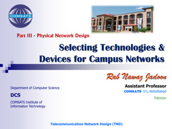
Volume 2, Issue 11, November– 2017International Journal of Innovative Science and Research TechnologyISSN No:-2456 –2165Cisco packet tracer is simulation software used todesign, configure, troubleshoot different ciscodevice [6] [7] and currently included IOT devicein Cisco packet tracer version 7.II.A. New Future of Cisco Packet Tracer 7.0 MOTIVATION Cisco currently release new version of ciscopacket tracer that include IOE device withclassically networking device.III.METHODOLOGYRegistration server for IoT devicesIOE devices and sensors in a new IoEdevices category: solar panel, powermeter, car, wireless home gateway, powermeter, motion detector, temperaturesensor, conveyor sensor,Programming languages for IoE.Single board Computer (SBC)Microcontroller Unit (MCUWireless IOE RFID sensor.Wireless IOE RFID items.In order to design campus network I used ciscopacket tracer .Cisco Packet Tracer is a networkingsimulator used for teaching and learning programby offering a unique combination ofrealistic[7][8].Benefits of Packet Tracer are: Offers arealisticvisualizationsimulationandPermits users to design, build, configure,and troubleshoot complex networksAllows students to explore concepts,conduct experiments,Currently released cisco packet tracer includednew feature like new device, sensor, andProgrammingLanguageswithclassicallynetworking device, those device stated below [4].Things and Components available in PacketTracer 7.0 Smart Things are smart object attached tothe Registration Server or Home Gatewaythrough a network interface. They aredivided into 4 subcategories: Smart City,Home, Industrial, and Power Grid. Components are smart objects that link tomicrocontroller (MCU-PT) or singleboarded computers (SBC-PT). Not have anetwork interface and rely on the MCU-PTor SBC-PT for network access. This smartobject can communicate through analog ordigital slots.IJISRT17NV09Fig. 1: First Lookup of Cisco Packet Tracer 7www.ijisrt.com44
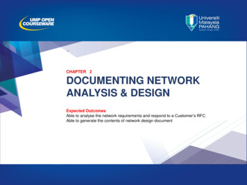
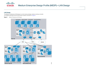
Volume 2, Issue 11, November– 2017International Journal of Innovative Science and Research TechnologyISSN No:-2456 –2165This microcontroller provide programmingenvironment (fig. 3) in order to control the smartthings connected to this two boards.Fig. 2: Four Categories of Smart ThingEach category has their own smart thing that isapplicable in categories. Example: in homecategories different smart things are there such assmart door, co detector, co2 detector, humidifier,home speaker, motion detector, humidity monitor,smoke detector, siren, webcam and smart window.Fig. 3: MCU and SBC MicrocontrollerIJISRT17NV09Fig. 4: Programming Environment Provided ByMCU (Microcontroller)www.ijisrt.com45
Volume 2, Issue 11, November– 2017International Journal of Innovative Science and Research TechnologyISSN No:-2456 –2165Fig. 5: IOE Registration ServerSmart things can directly register to IOEServerora Home Gateway configured with the IoEservice. Home Gateway have 4 Ethernet ports inaddition to a wireless access point configured withthe "Home Gateway" SSID.To secure wirelessconnection WEP / WPA-PSK / WPA2 enterprisecan be configured on home gateway. The figurebelow shows four internet of Things deviceconnected to a Home Gateway by using Ethernetcable and wireless. To connect the Home Gatewayto the Internet its Internet WAN Ethernet portavailable on home getaway.IJISRT17NV09Fig. 6: Home Gateway with Four Smart ThingsConnected To Home GatewayIV.IMPLEMENTATIONTo implement campus network design I proposedSmart Campus Network Design (SCND), todesign this proposed method different networkingdevice are used , those device are cisco 1941router , 2960 switch, 3560 switch, central officeserver , cell tower and some smart thing is alsoincluded in this design.Furthermore about thedevice is elaborated in table 1.www.ijisrt.com46
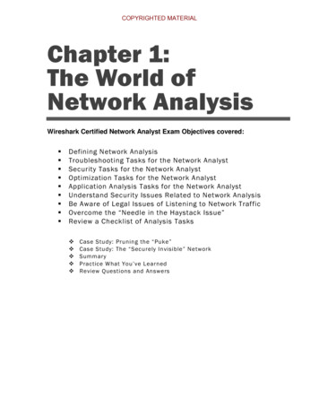
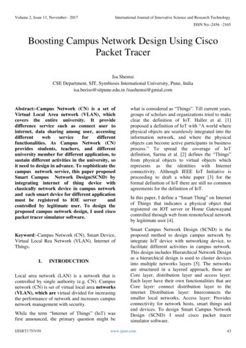
Volume 2, Issue 11, November– 2017International Journal of Innovative Science and Research TechnologyISSN No:-2456 –2165Fig. 7: Proposed ArchitectureA. Device Used for DesignNo Device1Router(1941)2345678910FunctionUsed to connect campusnetwork to the internetlayer twoUsed to distribute access toswitch (2960) the lower layerLayer threeUsed to perform intraswitch(3560) VLAN routingServerTo control smart thingregistered on it and providedifferenceserverfunctionalitiesCentral office Used to connect cellularserversystem to the routerMCUUsed to interconnectdifferent smart thingPcConnect to access layerFanUsed to ventilatethecampus based on someconditionWebcamControl the campusSirenProvide sound for someevent in the campusIJISRT17NV091112LightMotiondetector13Smart doorCell tower14Provide lightConnect to home getawayand provideDetection of motionConnect to home getawayand provideFunction based eventProvide cellular systemcoverage for different user15TabletUsed to control the campusfrom outside16Old carTo detect smoke17LCDTo display text18MotionsensorTo sense motion by mousemovementwww.ijisrt.comTable 1: Device Used for Implementation47
Volume 2, Issue 11, November– 2017International Journal of Innovative Science and Research TechnologyISSN No:-2456 –2165B. Device ConfigurationTo implement the campus network design oncisco packer tracer , I used class A IP address thatis 10.10.220.0/24 subnet and this subnet dividedinto eight subnet from this eight subnet, I usedfour of them and the rest are reserved for futurescalability. Core RouterRouter(config)#hostname coreroutercorerouter(config)#interface g0/0corerouter(config-if)#ip address 10.10.220.1255.255.255.224corerouter(config-if)#no shutdowncorerouter(config)#int g0/1corerouter(config-if)#ip add #no shcorerouter(config)#ipdhcp excluded-address209.165.20.225 209.165.20.229corerouter(config)#ipdhcp pool tellcorerouter(dhcp-config)#network fig)#dns-server 10.10.220.40Command for checking running configurationcorerouter#show running-configBuilding configuration.Current configuration : 1072 bytes!version 15.1no service timestamps log datetimemsecno service timestamps debug datetimemsecservice password-encryption!hostname corerouter!enable secret 5 1 mERr Me19uJMtOy6/CjrWm.7sd1!ipdhcp excluded-address 209.165.20.225209.165.20.229!ipdhcp pool tellnetwork 209.165.20.224 255.255.255.224IJISRT17NV09default-router 209.165.20.225dns-server 10.10.220.35!!!ipcefno ipv6 cef!license udipid CISCO1941/K9 snFTX1524UANM!spanning-tree mode pvst!interface GigabitEthernet0/0ip address 10.10.220.1 255.255.255.224duplex autospeed auto!interface GigabitEthernet0/1ip address 209.165.20.225 255.255.255.224duplex autospeed auto!interface Vlan1no ip addressshutdown!ip classlessip route 10.10.220.0 255.255.255.0 10.10.220.2ip route 10.10.220.0 255.255.255.224 10.10.220.2!ip flow-export version 9!no cdp run!!line con 0password 7 08224D43190C16!line aux 0!line vty 0 4password 7 08224D43190C16loginline vty 5 15password 7 08224D43190C16login!endwww.ijisrt.com48
Volume 2, Issue 11, November– 2017International Journal of Innovative Science and Research TechnologyISSN No:-2456 –2165 Distribution Layer DeviceSwitch(config)#hostname multlayerswitchmultlayerswitch(config)#vlan 10multlayerswitch(config-vlan)#name serverfarmmultlayerswitch(config-vlan)#vlan 20multlayerswitch(config-vlan)#name adminmultlayerswitch(config-vlan)#vlan ltlayerswitch(config-vlan)#vlan nfig)#ipdhcp excludedaddress 10.10.220.96 10.10.220.99multlayerswitch3(config)#ipdhcp work10.10.220.96 dhcp excludedaddress 10.10.220.128 10.10.220.130multlayerswitch3(config)#ipdhcp network10.10.220.128 )#dns-server10.10.220.40multlayerswitch#show running-configBuilding configuration.Current configuration : 2742 bytes!version 12.2no service timestamps log datetimemsecno service timestamps debug datetimemsecno service password-encryption!hostname multlayerswitch!ipdhcp excluded-address 10.10.220.6410.10.220.68ipdhcp excluded-address 10.10.220.9610.10.220.100IJISRT17NV09ipdhcp excluded-address 10.10.220.12810.10.220.130ipdhcp excluded-address 10.10.220.3310.10.220.35!ipdhcp pool serverroomnetwork 10.10.220.32 255.255.255.224default-router 10.10.220.33dns-server 10.10.220.35ipdhcp pool adminnetwork 10.10.220.64 255.255.255.224default-router 10.10.220.65dns-server 10.10.220.35ipdhcp pool mcusmartthingnetwork 10.10.220.96 255.255.255.224default-router 10.10.220.97dns-server 10.10.220.35ipdhcp pool getwaysmartthingnetwork 10.10.220.128 255.255.255.224default-router 10.10.220.129dns-server 10.10.220.35!!ip routing!spanning-tree mode pvstinterface FastEthernet0/1switchport access vlan 10switchport mode access!!interface FastEthernet0/3switchport access vlan 30switchport mode access!interface FastEthernet0/4switchport access vlan 20switchport mode access!!interface Vlan1no ip addressshutdown!interface Vlan10mac-address 00e0.f9c0.0001ip address 10.10.220.33 255.255.255.224!interface Vlan20www.ijisrt.com49
Volume 2, Issue 11, November– 2017International Journal of Innovative Science and Research TechnologyISSN No:-2456 –2165mac-address 00e0.f9c0.0002ip address 10.10.220.65 255.255.255.224!interface Vlan30mac-address 00e0.f9c0.0003ip address 10.10.220.97 255.255.255.224!interface Vlan40mac-address 00e0.f9c0.0004ip address 10.10.220.129 255.255.255.224!ip classlessip route 209.165.20.224 255.255.255.22410.10.220.1!ip flow-export version 9!no cdp run!line con 0!line aux 0!line vty 0 4login!!!endFig. 9: IOE Device Get IP Address DynamicallyC. Device SetupAfter configuration is done the device get IPaddress dynamically and IOE device registered toIOE server or home getaway.Fig. 8: Pc Gets IP Address DynamicallyIJISRT17NV09Fig. 10: Registering Smart Thing to IOE Serverwww.ijisrt.com50
Volume 2, Issue 11, November– 2017International Journal of Innovative Science and Research TechnologyISSN No:-2456 –2165The above Fig shows Registering IOE device toIOE server to control IOE device form remote orlocal by legitimate person that have username andpassword.Above fig shows Controlling ceiling fan bymaking off/low/high and also control light bymaking on/dim/off.Fig.13: Controlling Smart Thing Form RemoteNetworkFig. 11: Login page for IOT Register ServerLegitimate user can log the system from remote orlocal to control smart thing registered on thesystem.Fig. 14: Condition Making For Smart Thing onServerFig. 12: Controlling Smart Thing Form LocalIJISRT17NV09The Fig. 14: shows condition made for firesprinkler and smoke detector. If smoke levelsabove 10 the fire sprinkler, window, door andsiren are on else off.www.ijisrt.com51
Volume 2, Issue 11, November– 2017International Journal of Innovative Science and Research TechnologyISSN No:-2456 –2165Fig.15: Shows Fire Sprinkler and Siren Are onThe above fig shows Fire sprinkler and siren areon when smoke level above 10 to ventilate theplace and alarm the surrounding. To detect smokeold car was used. As old car has a lot of problem.Microcontroller unit (MCU) is a board used tointer connect smart thing and sensor forcontrollingandprovideprogrammingenvironment to manage the things connected to it.The following python program are written onMCU to control and safe resource used bydifference smart things.from gpio import *from time import *pinMode(4, OUT)print("BLINKING")while True:customWrite(1, "wel come");digitalWrite(2, LOW);customWrite(0, 0);customWrite(4, 0);if (digitalRead(3)):customWrite(3, 0);customWrite(0, 1);customWrite(1,"Warning");digitalWrite(2, HIGH);customWrite(4, 1);print("ALERT")def main():pinMode(0, OUT)pinMode(1, OUT)pinMode(2, OUT)pinMode(3, IN)IJISRT17NV09delay(1000)if name " main ":main()www.ijisrt.com52
Volume 2, Issue 11, November– 2017International Journal of Innovative Science and Research TechnologyISSN No:-2456 –2165Fig.16: Shows MCU Control the Smart Thing and Sensor Connected To It.The above Fig shows if motion is detected in caseof security the siren, alarm, webcam are on andLCD display warning text. To control this eventsthe above python program implemented on centralMCU.V.CONCLUSIONTo improve the campus network service, thispaper proposed Smart Campus NetworkDesign(SCND) by assimilating internet of thing devicewith classically network device.Each smart deviceregistered to IOT server or home getaway andcontrolled by legitimate user.This design alsoinclude Hierarchical Network Design as ahierarchical design is used to group devices intomultiple layers. This paper also present aboutMicrocontroller unit (MCU) that used tointerconnect different IOE device and controlthem by coding.To design the proposed campusnetwork design I used cisco packet tracersimulator software.IJISRT17NV09REFERENCE[1]. S. Haller S. Karnouskos and C. Schroth "TheInternet of Things in an Enterprise Context "in Future Internet-FIS 2008 Lecture Notes inComputer Science Vol. 5468 2009 pp 14-28.[2]. A. C. Sarma and J. Girão "Identities in theFuture Internet of Things” in WirelessPersonal Communications 49.3 2009 pp. 353363.[3]. Roberto Minerva AbiyBiru "Towards aDefinition of the Internet of Things” IEEE IoTInitiative white paper.[4]. gs/pt7-iot-devices-configuration.html.[5]. Current, John R., Charles S. ReVelle, andJared L. Cohon. "The hierarchical networkdesign problem." European Journal ofOperational Research 27.1 (1986): 57-66.[6]. Qin, X. U. E. "Simulation ExperimentalTeaching of Computer Network Based onwww.ijisrt.com53
Volume 2, Issue 11, November– 2017International Journal of Innovative Science and Research TechnologyISSN No:-2456 –2165Packet Tracer [J]." Research and Explorationin Laboratory 2 (2010): 57-59.[7]. Sun, L., Wu, J., Zhang, Y., & Yin, H. (2013,April). Comparison between physical devicesand simulator software for Cisco networktechnology teaching. In Computer Science &Education (ICCSE), 2013 8th InternationalConference on (pp. 1357-1360). IEEE.[8]. Qin, X. U. E. "Simulation ExperimentalTeaching of Computer Network Based onPacket Tracer [J]." Research and Explorationin Laboratory 2 (2010): 57-59.IJISRT17NV09www.ijisrt.com54
in Cisco packet tracer version 7. II. MOTIVATION Cisco currently release new version of cisco packet tracer that include IOE device with classically networking device. III. METHODOLOGY In order to design campus network I used cisco packet tracer .Cisco Packet Tracer is a networking