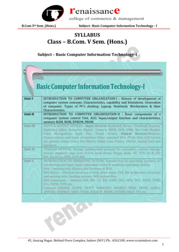
Transcription
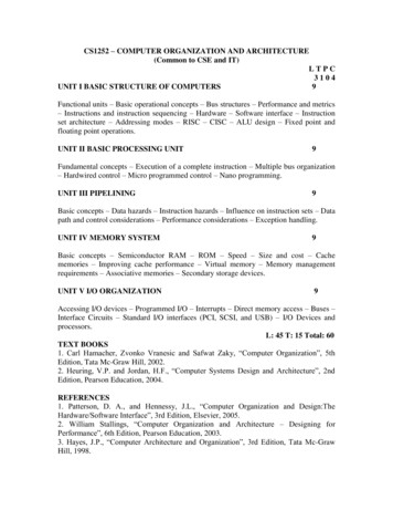
CS1252 – COMPUTER ORGANIZATION AND ARCHITECTURE(Common to CSE and IT)LTPC3104UNIT I BASIC STRUCTURE OF COMPUTERS9Functional units – Basic operational concepts – Bus structures – Performance and metrics– Instructions and instruction sequencing – Hardware – Software interface – Instructionset architecture – Addressing modes – RISC – CISC – ALU design – Fixed point andfloating point operations.UNIT II BASIC PROCESSING UNIT9Fundamental concepts – Execution of a complete instruction – Multiple bus organization– Hardwired control – Micro programmed control – Nano programming.UNIT III PIPELINING9Basic concepts – Data hazards – Instruction hazards – Influence on instruction sets – Datapath and control considerations – Performance considerations – Exception handling.UNIT IV MEMORY SYSTEM9Basic concepts – Semiconductor RAM – ROM – Speed – Size and cost – Cachememories – Improving cache performance – Virtual memory – Memory managementrequirements – Associative memories – Secondary storage devices.UNIT V I/O ORGANIZATION9Accessing I/O devices – Programmed I/O – Interrupts – Direct memory access – Buses –Interface Circuits – Standard I/O interfaces (PCI, SCSI, and USB) – I/O Devices andprocessors.L: 45 T: 15 Total: 60TEXT BOOKS1. Carl Hamacher, Zvonko Vranesic and Safwat Zaky, “Computer Organization”, 5thEdition, Tata Mc-Graw Hill, 2002.2. Heuring, V.P. and Jordan, H.F., “Computer Systems Design and Architecture”, 2ndEdition, Pearson Education, 2004.REFERENCES1. Patterson, D. A., and Hennessy, J.L., “Computer Organization and Design:TheHardware/Software Interface”, 3rd Edition, Elsevier, 2005.2. William Stallings, “Computer Organization and Architecture – Designing forPerformance”, 6th Edition, Pearson Education, 2003.3. Hayes, J.P., “Computer Architecture and Organization”, 3rd Edition, Tata Mc-GrawHill, 1998.
UNIT IBASIC STRUCTURE OF COMPUTERS Functional units Basic operational concepts Bus structures Performance and metrics Instructions and instruction sequencing Hardware Software interface Instruction set architecture Addressing modes RISC CISC ALU design Fixed point and floating point operations
BASIC STRUCTURE OF COMPUTERS:Computer Organization:It refers to the operational units and their interconnections that realize thearchitectural specifications.It describes the function of and design of the various units of digital computer thatstore and process information.Computer hardware:Consists of electronic circuits, displays, magnetic and optical storage media,electromechanical equipment and communication facilities.Computer Architecture:It is concerned with the structure and behaviour of the computer.It includes the information formats, the instruction set and techniques foraddressing memory.Functional UnitsA computer consists of 5 main parts.InputMemoryArithmetic and logicOutputControl UnitsFunctional units of a Computer
Input unit accepts coded information from human operators, fromelectromechanical devices such as keyboards, or from other computersover digital communication lines.The information received is either stored in the computers memory forlater reference or immediately used by the arithmetic and logic circuitry toperform the desired operations.The processing steps are determined by a program stored in the memory.Finally the results are sent back to the outside world through the outputunit.All of these actions are coordinated by the control unit.The list of instructions that performs a task is called a program.Usually the program is stored in the memory.The processor then fetches the instruction that make up the program fromthe memory one after another and performs the desire operations.1.1 Input Unit: Computers accept coded information through input units, which read thedata. Whenever a key is pressed, the corresponding letter or digit isautomatically translated into its corresponding binary code and transmittedover a cable to either the memory or the processor.Some input devices are Joysticks Trackballs Mouses Microphones (Capture audio input and it is sampled & it isconverted into digital codes for storage and processing).1.2.Memory Unit:It stores the programs and data.There are 2 types of storage classes Primary SecondaryPrimary Storage:It is a fast memory that operates at electronic speeds.Programs must be stored in the memory while they arebeing executed.The memory contains large no of semiconductor storagecells.Each cell carries 1 bit of information.The Cells are processed in a group of fixed size calledWords.To provide easy access to any word in a memory,a distinctaddress is associated with each word location.
Addresses are numbers that identify successive locations.The number of bits in each word is called the word length.The word length ranges from 16 to 64 bits.There are 3 types of memory.They are RAM(Random Access Memory) Cache memory Main MemoryRAM:Memory in which any location can be reached in short and fixed amount of timeafter specifying its address is called RAM.Time required to access 1 word is called Memory Access Time.Cache Memory:The small,fast,RAM units are called Cache. They are tightly coupled withprocessor to achieve high performance.Main Memory:The largest and the slowest unit is called the main memory.1.3. ALU:Most computer operations are executed in ALU.Consider a example,Suppose 2 numbers located in memory are to be added. They are broughtinto the processor and the actual addition is carried out by the ALU. The sum may thenbe stored in the memory or retained in the processor for immediate use.Access time to registers is faster than access time to the fastest cache unit inmemory.1.4. Output Unit:Its function is to send the processed results to the outside world. eg.PrinterPrinters are capable of printing 10000 lines per minute but its speed iscomparatively slower than the processor.1.5. Control Unit:The operations of Input unit, output unit, ALU are co-ordinate by thecontrol unit.The control unit is the Nerve centre that sends control signals to otherunits and senses their states.Data transfers between the processor and the memory are also controlledby the control unit through timing signals.The operation of computers are, The computer accepts information in the form of programs anddata through an input unit and stores it in the memory.
Information stored in the memory is fetched, under programcontrol into an arithmetic and logic unit, where it is processed.Processed information leaves the computer through an output unit.All activities inside the machine are directed by the control unit.BASIC OPERATIONAL CONCEPTS:The data/operands are stored in memory.The individual instruction are brought from the memory to the processor, whichexecutes the specified operation.Eg:1Add LOC A ,R1Instructions are fetched from memory and the operand at LOC A is fetched. It is thenadded to the contents of R0, the resulting sum is stored in Register R0.Eg:2Load LOC A, R1Transfer the contents of memory location A to the register R1.Eg:3Add R1 ,R0Add the contents of Register R1 & R0 and places the sum into R0.Fig:Connection between Processor and Main MemoryInstruction Register(IR)Program Counter(PC)
Memory Address Register(MAR)Memory Data Register(MDR)Instruction Register (IR): It holds the instruction that is currently being executed. It generates the timing signals.Program Counter (PC):It contains the memory address of the next instruction to be fetched for execution.Memory Address Register (MAR):It holds the address of the location to be accessed.Memory Data Register (MDR): It contains the data to written into or read out of the address location. MAR and MDR facilitates the communication with memory.Operation Steps: The program resides in memory. The execution starts when PC is point to the firstinstruction of the program. MAR read the control signal. The Memory loads the address word into MDR.The contents are transferred toInstruction register. The instruction is ready to be decoded & executed.Interrupt:Normal execution of the program may be pre-empted if some device requiresurgent servicing.Eg.Monitoring Device in a computer controlled industrial process may detect adangerous condition.In order to deal with the situation immediately, the normal execution of thecurrent program may be interrupted & the device raises an interrupt signal.The processor provides the requested service called the Interrupt ServiceRoutine(ISR).ISR save the internal state of the processor in memory before servicing theinterrupt because interrupt may alter the state of the processor.When ISR is completed, the state of the processor is restored and the interruptedprogram may continue its execution.
BUS STRUCTURES:A group of lines that serves as the connection path to several devices is called a Bus.A Bus may be lines or wires or one bit per line.The lines carry data or address or control signal.There are 2 types of Bus structures. They areSingle Bus StructureMultiple Bus Structure3.1.Single Bus Structure:It allows only one transfer at a time.It costs low.It is flexible for attaching peripheral devices.Its Performance is low.3.2.Multiple Bus Structure:It allows two or more transfer at a time.It costs high.It provides concurrency in operation.Its Performance is high.Devices Connected with BusElectro-mechanical decvices(Keyboard,printer)SpeedSlowMagnetic / optical diskHighMemory & processing unitsVery HighThe Buffer Register when connected with the bus, carries the information during transfer.The Buffer Register prevents the high speed processor from being locked to a slow I/Odevice during a sequence of data transfer.
SOFTWARE:System Software is a collection of programs that are executed as needed to performfunction such as, Receiving & Interpreting user commands. Entering & editing application program and storing them as files in secondaryStorage devices. Managing the storage and retrieval of files in Secondary Storage devices. Running the standard application such as word processor, games, andspreadsheets with data supplied by the user. Controlling I/O units to receive input information and produce output results. Translating programs from source form prepared by the user into object form. Linking and running user-written application programs with existing standardlibrary routines.Software is of 2 types.They areApplication programSystem programApplication Program:It is written in high level programming language(C,C ,Java,Fortran)The programmer using high level language need not know the details of machineprogram instruction.System Program:(Compiler,Text Editor,File)Compiler:It translates the high level language program into the machine language program.Text Editor:It is used for entering & editing the application program.System software Component - OS(OPERATING SYSTEM)Operating System :It is a large program or a collection of routines that is used to control the sharingof and interaction among various computer units.Functions of OS:Assign resources to individual application program.Assign memory and magnetic disk space to program and data files.
Move the data between the memory and disk units.Handles I/O operation.Fig:User Program and OS routine sharing of the processSteps:1. The first step is to transfer the file into memory.2. When the transfer is completed, the execution of the program starts.3. During time period „t0‟ to „t1‟ , an OS routine initiates loading the applicationprogram from disk to memory, wait until the transfer is complete and then passes theexecution control to the application program & print the results.4. Similar action takes place during „t2‟ to „t3‟ and „t4‟ to „t5‟.5. At „t5‟, Operating System may load and execute another application program.6. Similarly during „t0‟ to „t1‟ , the Operating System can arrange to print theprevious program‟s results while the current program is being executed.7. The pattern of managing the concurrent execution of the several applicationprograms to make the best possible use of computer resources is called the multiprogramming or multi-tasking.
PERFORMANCE:For best performance, it is necessary to design the compiler, machine instructionset and hardware in a co-ordinate way.Elapsed Time the total time required to execute the program is called the elapsed time.It depends on all the units in computer system.Processor Time The period in which the processor is active is called the processor time.It depends on hardware involved in the execution of the instruction.Fig: The Processor CacheA Program will be executed faster if the movement of instruction and databetween the main memory and the processor is minimized, which is achieved by usingthe Cache.Processor clock:Clock The Processor circuits are controlled by a timing signal called a clock.Clock Cycle The cycle defines a regular time interval called clock cycle.Clock Rate,R 1/PWhere, P Length of one clock cycle.Basic Performance Equation:T (N*S)/RWhere, T Performance ParameterR Clock Rate in cycles/sec
N Actual number of instruction executionS Average number of basic steps needed to execute one machine instruction.To achieve high performance,N,S RPipelining and Superscalar operation:Pipelining A Substantial improvement in performance can be achieved by overlappingthe execution of successive instruction using a technique called pipelining.Superscalar Execution It is possible to start the execution of several instruction ineverey clock cycles (ie)several instruction can be executed in parallel by creatingparallel paths.This mode of operation is called the Superscalar execution.Clock Rate:There are 2 possibilities to increase the clock rate(R).They are,Improving the integrated Chip(IC) technology makes logical circuits faster.Reduce the amount of processing done in one basic step also helps to reduce theclock period P.Instruction Set:CISC AND RISC:The Complex instruction combined with pipelining would achieve the bestperformance.It is much easier to implement the efficient pipelining in processor with simpleinstruction set.SimpleSimple InstructionInstruction setSetRISCRISCCISCCISC(Reduced Instruction Set Computer)It is the design of the instruction setof a processor with simple instructionCOMHigh levelLanguageProgramCompilerTranslated into(Complex Instruction Set Computer)It is the design of the instruction setof a processor with complex instruction.Machineinstruction
Functions of Compiler:The compiler re-arranges the program instruction to achieve better performance.The high quality compiler must be closely linked to the processor architecture toreduce the total number of clock cycles.Performance Measurement:The Performance Measure is the time it takes a computer to execute a givenbenchmark.A non-profit organization called SPEC(System Performance EvaluationCorporation) selects and publishes representative application program.Running time on reference computerSPEC rating Running time on computer under testThe Overall SPEC rating for the computer is given by,n1/nSPEC rating ( Π SPECi)Where,n Numberof programsin the suite(SPEC)i rating i 1for program I in the suite.INSTRUCTION AND INSTRUCTION SEQUENCINGA computer must have instruction capable of performing the following operations. Theyare, Data transfer between memory and processor register.Arithmetic and logical operations on data.Program sequencing and control.I/O transfer.Register Transfer Notation:The possible locations in which transfer of information occurs are,
Memory LocationProcessor registerRegisters in I/O sub-system.LocationHardware BinaryEgAddressLOC,PLACE,A,VAR2 R1 [LOC]MemoryR0,R1, .ProcessorI/O Registers[R3] [R1] [R2]DATAIN,DATAOUTDescriptionThe contents of memorylocation are transferredto. the processor register.Add the contents ofregister R1 &R2 andplaces .their sum intoregister R3.It is.called Register TransferNotation.Provides StatusinformationAssembly Language Notation:Assembly LanguageFormatMove LOC,R1DescriptionAdd R1,R2,R3Add the contents of register R1 & R2 and places their suminto register R3.Transfers the contents of memory location to the processorregister R1.Basic Instruction Types:InstructionSyntaxTypeThree Address dd A,B,CAdd values of variableA ,B & place the resultinto c.Add the values of A,B& place the result intoB.Content ofaccumulator add withcontent of B.Two AddressOperation Source,DestinationAdd A,BOne AddressOperation OperandAdd BInstruction Execution and Straight–line Sequencing:Instruction Execution:There are 2 phases for Instruction Execution. They are,
Instruction Fetch Instruction ExecutionInstruction Fetch:The instruction is fetched from the memory location whose address is in PC.This isplaced in IR.Instruction Execution:Instruction in IR is examined to determine whose operation is to be performed.Program execution Steps:To begin executing a program, the address of first instruction must be placed inPC.The processor control circuits use the information in the PC to fetch & executeinstructions one at a time in the order of increasing order.This is called Straight line sequencing.During the execution of eachinstruction,the PC is incremented by 4 to point the address of next instruction.Fig: Program ExecutionBranching:The Address of the memory locations containing the n numbers are symbolicallygiven as NUM1,NUM2 .NUMn.
Separate Add instruction is used to add each number to the contents of registerR0.After all the numbers have been added,the result is placed in memory locationSUM.Fig:Straight Line Sequencing Program for adding ‘n’ numbersUsing loop to add ‘n’ numbers:Number of enteries in the list „n‟ is stored in memory location M.Register R1 isused as a counter to determine the number of times the loop is executed.Content location M are loaded into register R1 at the beginning of the program.It starts at location Loop and ends at the instruction.Branch 0.During eachpass,the address of the next list entry is determined and the entry is fetched andadded to R0.Decrement R1
It reduces the contents of R1 by 1 each time through the loop.Branch 0LoopA conditional branch instruction causes a branch only if a specified condition issatisfied.Fig:Using loop to add ‘n’ numbers:Conditional Codes:Result of various operation for user by subsequent conditional branch instructionis accomplished by recording the required information in individual bits often calledCondition code Flags.Commonly used flags:
N(Negative) set to 1 if the result is –ve ,otherwise cleared to 0.Z(Zero) set to 1 if the result is 0 ,otherwise cleared to 0.V(Overflow) set to 1 if arithmetic overflow occurs ,otherwise cleared to 0.C(Carry)set to 1 if carry and results from the operation ,otherwise cleared to 0.ADDRESSING MODESThe different ways in which the location of an operand is specified in an instruction iscalled as Addressing mode.Generic Addressing Modes: Immediate modeRegister modeAbsolute modeIndirect modeIndex modeBase with indexBase with index and offsetRelative modeAuto-increment modeAuto-decrement modeImplementation of Variables and Constants:Variables:The value can be changed as needed using the appropriate instructions.There are 2 accessing modes to access the variables. They are Register Mode Absolute ModeRegister Mode:The operand is the contents of the processor register.The name(address) of the register is given in the instruction.Absolute Mode(Direct Mode):The operand is in new location.The address of this location is given explicitly in the instruction.
Eg: MOVE LOC,R2The above instruction uses the register and absolute mode.The processor register is the temporary storage where the data in the register are accessedusing register mode.The absolute mode can represent global variables in the program.ModeAssembler SyntaxRegister modeAbsolute modeRiLOCAddressing FunctionEA RiEA LOCWhere EA-Effective AddressConstants:Address and data constants can be represented in assembly language using ImmediateMode.Immediate Mode.The operand is given explicitly in the instruction.Eg: Move 200 immediate ,R0It places the value 200 in the register R0.The immediate mode used to specify the valueof source operand.In assembly language, the immediate subscript is not appropriate so # symbol is used.It can be re-written asMove #200,R0Assembly Syntax:Addressing FunctionImmediate #valueOperand valueIndirection and Pointers:Instruction does not give the operand or its address explicitly.Instead it providesinformation from which the new address of the operand can be determined.This addressis called effective Address(EA) of the operand.
Indirect Mode:The effective address of the operand is the contents of a register .We denote the indirection by the name of the register or new address given in theinstruction.Fig:Indirect ModeAdd (A),R0Add (R1),R0B OperandOperandAddress of an operand(B) is stored into R1 register.If we want this operand,we can get itthrough register R1(indirection).The register or new location that contains the address of an operand is called the pointer.ModeAssembler SyntaxIndirectAddressing FunctionRi , LOCEA [Ri] or EA [LOC]Indexing and Arrays:Index Mode:The effective address of an operand is generated by adding a constant value to thecontents of a register.The constant value uses either special purpose or general purpose register.We indicate the index mode symbolically as,X(Ri)Where X – denotes the constant value contained in the instructionRi – It is the name of the register involved.The Effective Address of the operand is,EA X [Ri]
The index register R1 contains the address of a new location and the value of X definesan offset(also called a displacement).To find operand,First go to Reg R1 (using address)-read the content from R1-1000Add the content 1000 with offset 20 get the result.1000 20 1020Here the constant X refers to the new address and the contents of index registerdefine the offset to the operand.The sum of two values is given explicitly in the instruction and the other is storedin register.Eg: Add 20(R1) , R2 (or) EA 1000 20 1020Index ModeAssembler SyntaxAddressing FunctionIndexBase with IndexBase with Index and offsetX(Ri)(Ri,Rj)X(Ri,Rj)EA [Ri] XEA [Ri] [Rj]EA [Ri] [Rj] XRelative Addressing:It is same as index mode. The difference is, instead of general purpose register, here wecan use program counter(PC).Relative Mode:The Effective Address is determined by the Index mode using the PC in place ofthe general purpose register (gpr).This mode can be used to access the data operand. But its most common use is tospecify the target address in branch instruction.Eg. Branch 0 LoopIt causes the program execution to goto the branch target location. It is identifiedby the name loop if the branch condition is satisfied.ModeRelativeAssembler SyntaxX(PC)Additional Modes:There are two additional modes. They areAddressing FunctionEA [PC] X
Auto-increment mode Auto-decrement modeAuto-increment mode:The Effective Address of the operand is the contents of a register in theinstruction.After accessing the operand, the contents of this register is automaticallyincremented to point to the next item in the list.ModeAssembler syntaxAuto-increment(Ri) Addressing FunctionEA [Ri];Increment RiAuto-decrement mode:The Effective Address of the operand is the contents of a register in theinstruction.After accessing the operand, the contents of this register is automaticallydecremented to point to the next item in the list.ModeAuto-decrementAssembler Syntax-(Ri)Addressing FunctionEA [Ri];Decrement RiCISCPronounced sisk, and stands for Complex Instruction Set Computer. Most PC's use CPUbased on this architecture. For instance Intel and AMD CPU's are based on CISCarchitectures.Typically CISC chips have a large amount of different and complex instructions. Thephilosophy behind it is that hardware is always faster than software, therefore one shouldmake a powerful instruction set, which provides programmers with assembly instructionsto do a lot with short programs.In common CISC chips are relatively slow (compared to RISC chips) per instruction, butuse little (less than RISC) instructions.RISCPronounced risk, and stands for Reduced Instruction Set Computer. RISC chips evolvedaround the mid-1980 as a reaction at CISC chips. The philosophy behind it is that almostno one uses complex assembly language instructions as used by CISC, and people mostlyuse compilers which never use complex instructions. Apple for instance uses RISC chips.Therefore fewer, simpler and faster instructions would be better, than the large, complexand slower CISC instructions. However, more instructions are needed to accomplish atask.An other advantage of RISC is that - in theory - because of the more simple instructions,
RISC chips require fewer transistors, which makes them easier to design and cheaper toproduce.Finally, it's easier to write powerful optimised compilers, since fewer instructions exist.RISC vs CISCThere is still considerable controversy among experts about which architecture is better.Some say that RISC is cheaper and faster and therefor the architecture of the future.Others note that by making the hardware simpler, RISC puts a greater burden on thesoftware. Software needs to become more complex. Software developers need to writemore lines for the same tasks.Therefore they argue that RISC is not the architecture of the future, since conventionalCISC chips are becoming faster and cheaper anyway.RISC has now existed more than 10 years and hasn't been able to kick CISC out of themarket. If we forget about the embedded market and mainly look at the market for PC's,workstations and servers I guess a least 75% of the processors are based on the CISCarchitecture. Most of them the x86 standard (Intel, AMD, etc.), but even in the mainframeterritory CISC is dominant via the IBM/390 chip. Looks like CISC is here to stay Is RISC than really not better? The answer isn't quite that simple. RISC and CISCarchitectures are becoming more and more alike. Many of today's RISC chips supportjust as many instructions as yesterday's CISC chips. The PowerPC 601, for example,supports more instructions than the Pentium. Yet the 601 is considered a RISC chip,while the Pentium is definitely CISC. Further more today's CISC chips use manytechniques formerly associated with RISC chips.ALU DesignIn computing an arithmetic logic unit (ALU) is a digital circuit that performs arithmeticand logical operations. The ALU is a fundamental building block of the centralprocessing unit (CPU) of a computer, and even the simplest microprocessors contain onefor purposes such as maintaining timers. The processors found inside modern CPUs andgraphics processing units (GPUs) accommodate very powerful and very complex ALUs;a single component may contain a number of ALUs.Mathematician John von Neumann proposed the ALU concept in 1945, when he wrote areport on the foundations for a new computer called the EDVAC. Research into ALUsremains an important part of computer science, falling under Arithmetic and logicstructures in the ACM Computing Classification SystemNumerical systemsAn ALU must process numbers using the same format as the rest of the digital circuit.The format of modern processors is almost always the two's complement binary numberrepresentation. Early computers used a wide variety of number systems, including ones'complement, Two's complement sign-magnitude format, and even true decimal systems,with ten tubes per digit.
ALUs for each one of these numeric systems had different designs, and that influencedthe current preference for two's complement, as this is the representation that makes iteasier for the ALUs to calculate additions and subtractions.The ones' complement and Two's complement number systems allow for subtraction tobe accomplished by adding the negative of a number in a very simple way which negatesthe need for specialized circuits to do subtraction; however, calculating the negative inTwo's complement requires adding a one to the low order bit and propagating the carry.An alternative way to do Two's complement subtraction of A-B is present a 1 to the carryinput of the adder and use B rather than B as the second input.Practical overviewMost of a processor's operations are performed by one or more ALUs. An ALU loadsdata from input registers, an external Control Unit then tells the ALU what operation toperform on that data, and then the ALU stores its result into an output register. Othermechanisms move data between these registers and memory.Simple operationsA simple example arithmetic logic unit (2-bit ALU) that does AND, OR, XOR, andadditionMost ALUs can perform the following operations:Integer arithmetic operations (addition, subtraction, and sometimes multiplicationand division, though this is more expensive)Bitwise logic operations (AND, NOT, OR, XOR)Bit-shifting operations (shifting or rotating a word by a specified number of bitsto the left or right, with or without sign extension). Shifts can be interpreted asmultiplications by 2 and divisions by 2.Complex operationsEngineers can design an Arithmetic Logic Unit to calculate any operation. The morecomplex the operation, the more expensive the ALU is, the more space it uses in theprocessor, the more power it dissipates. Therefore, engineers compromise. They make theALU powerful enough to make the processor fast, but yet not so complex as to becomeprohibitive. For example, computing the square root of a number might use:1. Calculation in a single clock Design an extraordinarily complex ALU thatcalculates the square root of any number in a single step.2. Calculation pipeline Design a very complex ALU that calculates the square rootof any number in several steps. The intermediate results go through a series ofcircuits arranged like a factory production line. The ALU can accept new numbersto calculate even before having finished the previous ones. The ALU
Computer Organization: It refers to the operational units and their interconnections that realize the architectural specifications. It describes the function of and design of the various units of digital computer that store and process information. Computer hardware: Consists of electroni