Transcription
COURSE FILECOMPUTER ORGANIZATIONIV B.Tech. - I SemesterDepartment of Computer Science and EngineeringGAYATRI VIDYA PARISHAD COLLEGE OF ENGINEERING FOR WOMENwww.gvpcew.ac.in(Approved by AICTE & Affiliated to JNTUK)Estd. – 2008Gandhi Nagar, Madhurawada, Visakhapatnam, Andhra Pradesh 530048 .
Course Objectives & OutcomesCourse Objectives:- Comprehensive knowledge of computer system including the analysis and design ofcomponents of the system Understanding RTL, Micro operations, ALU, Organization of stored program computer,types of instructions and design of basic components of the system Illustration of data paths and control flow for sequencing in CPUs, Microprogramming ofcontrol unit of CPU Illustration of algorithms for basic arithmetic operations using binary and decimalrepresentation Description of different parameters of a memory system, organization and mapping ofvarious types of memories Describes the means of interaction devices with CPU, their characteristics, modes andintroduction multiprocessors.Course Outcomes:-After completing this Course, the student should be able to:Understand the architecture of a modern computer with its various processing units. Also theperformance measurement of the computer system. In addition to this the management system ofcomputer.Students have a thorough understanding of the basic structure and operation of a digitalcomputer. Able to discuss in detail the operation of the arithmetic unit including the algorithms &implementation of fixed-point and floating-point addition, subtraction, multiplication &division. Able to discuss in detail the operation of the arithmetic unit including the algorithms &implementation of fixed-point and floating-point addition, subtraction, multiplication &division. Students have a thorough understanding of Micro Program Control
Students can calculate the effective address of an operand by addressing modes Understanding of how a computer performs arithmetic operation of positive and negativenumbers. Explain the function of each element of a memory hierarchy, Cache memory and itsimportance. Students can understand how cache mapping occurs in computer and can solve variousproblems related to this. Study the hierarchical memory system including cache memories and virtual memory. Able to identify and compare different methods for computer I/O Able to discuss about advantages of parallel processing, multiprocessors.
1. SyllabusUNIT-IBASIC STRUCTURE OF COMPUTERS: Computer Types, Functional units, Basicoperationalconcepts, Bus structures, Software, Performance, multiprocessors and multicomputers. Data types, Complements, Data Representation. Fixed Point Representation.Floating – Point Representation.Error Detection codes.COMPUTER ARITHMETIC: Addition and subtraction, multiplicationalgorithms,Division Algorithms, Floating point Arithmetic operations. Decimal Arithmetic unit,Decimal Arithmetic operations.UNIT-IIREGISTER TRANSFER LANGUAGE AND MICRO-OPERATIONS:Register Transfer language. Register Transfer, Bus and memory transfer, Arithmetic Microoperations,logic micro operations, shift micro-operations, Arithmetic logic shift unit.Instruction codes. Computer Registers Computer instructions – Instruction cycle. MemoryReference Instructions. Input Outputand Interrupt.CENTRAL PROCESSING UNIT - Stack organization. Instruction formats. Addressingmodes. DATA Transfer and manipulation. Program control. Reduced Instruction setcomputerUNIT-IIIMICRO PROGRAMMED CONTROL: Control memory, Address sequencing, microprogram example, Design of control unit-Hard wired control. Micro programmed control.UNIT-IVTHE MEMORY SYSTEM: Memory Hierarchy, Main memory, Auxiliary memory,Associative memory, Cache memory, Virtual memory, Memory management hardwareUNIT-VINPUT-OUTPUT ORGANIZATION : Peripheral Devices, Input-Output Interface,Asynchronous data transfer Modes of Transfer, Priority Interrupt, Direct memory Access,Input –Output Processor (IOP), SerialCommunication;UNIT-VIPIPELINE AND VECTOR PROCESSING: Parallel Processing, Pipelining, ArithmeticPipeline, Instruction Pipeline, RISC Pipeline Vector Processing, Array Processors. Multiprocessors: Characteristics of Multiprocessors, Interconnection Structures, Inter processorArbitration. Inter processor Communication and Synchronization, Cache Coherence.Text Books:1.2.M. Moris Mano (2006), Computer System Architecture, 3 rd edition, Pearson/PHI, India.Carl Hamacher, ZvonksVranesic, SafeaZaky (2002), Computer Organization, 5th edition, McGraw Hill,New Delhi, India.Reference Books:1.Computer Organization Architecture- William Stallings (2006), 7th edition, PHI/PEARSON.
2.Computer Architecture and Organization-John P.Hayes ,McGraw Hill, Internationaleditions,2002.Lecture PlanLectureno.1.UnitNumberITopic2.IComputer Types, functional Units and Basic Operational Concepts, Busstructure, software, performance multi processor and multi computer3.IData Types ,Number systems, octal and hexadecimal nos, decimal andalphanumeric representation4.IComplments-10’s and 9’s Complements; 2’s ans 1’s Complements;Subtraction of unsigned Nos; fixed point representation and Integerrepresentation;5.IAddition of two numbers in signed magnitude system; 2’s complementaddition, subtraction; overflow and overflow detection and decimal fixedpoint representation6.IFloating point representation& Error detection codes7.IIntroduction to computer Arithmetic, addition and subtraction algorithmfor signed magnitude numbers and hardware implementation; additionand subtraction for signed 2’s complement data8.IMultiplication algorithm: Hardware implementation for signedmagnitude data, hardware & algorithm;9.IBooth multiplication algorithm; Array multiplier10.IDivision Algorithm: Hardware implementation for signed magnitudedata, hardware algorithm and other algorithm.11.IFloating point Arithmetic operations: Basic considerations, registerconfigurations, addition, subtraction, multiplication and division12.IDecimal Arithmetic Unit: BCD Adder and BCD Subtraction13.IHardware and algorithm for Decimal Arithmetic Operations: Additionand subtraction.Introduction to Computer architecture and Organization
14.IHardware and algorithm for Decimal Arithmetic Operations:multiplication and division, floating point operations15.IIRegister transfer Language, Register Transfer, Bus and Memory Transfer16.IIArithmetic Micro operations; Logic Micro operations17.IIShift micro operations, Arithmetic logic shift unit18.IIInstruction Codes, Computer register19.IIComputer Instruction and format, Instruction Cycle20.IIMemory Reference Instructions, Input-Output and Interrupt21.IIStack Organization, register Stack, memory stack, Reverse polishnotation, Conversion to RPN, Evaluation of arithmetic expression22.IIInstruction Formats, 3-types of CPU organization, 3,2,1,0 addressinstruction formats, RISC Instructions23.IIAddressing modes; Data Transfer and manipulation instructions24.IIProgram Control Instructions, Subroutine call and return instructions,Program interrupts and types of interrupts25.IIRISC Vs CISC; Overlapping Register windows; Berkeley RISCI26.IIIControl memory27.IIIAddress Sequencing28.IIIMicro Program Example: computer configuration, instruction format andsymbolic microinstructions; The fetch routine, symbolic microprogramand binary microprogram29.IIIDesign of Control Unit: Hard wiredcontrol.and Micro programmed control30.IVMemory Hierarchy, Main memory: RAM and ROM chips, memoryaddress map, memory connection to CPU; Auxiliary memory: MagneticDisks and Magnetic Tapes31.IVAssociative Memory: Hardware Organization, Match Logic, readoperation and write operation
32.IVDirect mapping, Set-Associative Mapping, Writing into cache and cacheinitialization33.IVVirtual memory: Address Space and Memory Space, Address Mappingusing pages; Associative memory page table, Page replacement34.IV35.VMemory management hardware: Segmented page mapping, Numericalexample, Memory ProtectionPeripheral Devices, I/O Interface: I/O bus and interface modules; I/O vsMemory Bus, Isolated vs memory mapped I/O, Examples of I/OInterface36.VAsynchronous Data Transfer: Strobe Control, handshaking,asynchronous serial transfer; Asynchronous Commn Interface, First-infirst out buffer37.VModes of Transfer: Examples of Programmed I/O, Interrupt initiated I/Osoftware considerations; Priority Interrupt: Daisy Chaining Priority,parallel priority Interrupt, priority encoder,38.V39.VInterrupt cycle, software routines and initial and final operations,Direct Memory Access: DMA Controller and DMA TransferInput Output Processor(IOP): CPU –IOP Communication,40.VIBM 370 I/o channel, Intel 8089 IOP41.VSerial Communication: Character oriented protocol,42.VTransmission example, Data transparency and Bit-oriented protocol43.VIParallel Processing44.VIPipelining, general considerations45.VIArithmetic Pipeline, Instruction Pipeline46.VIRISC Pipeline; Vector Processing: vector operations, matrixmultiplication, memory interleaving,47.VIsuperscalar processors and super computers48.VIArray Processors: Attached Array Processor, SIMD Array Processor49.VICharacteristics of multi processors
50.VIInterconnection Structure: Timeshared Common Bus, MultiportMemory, Crossbar Switch, Multistage switching network, HypercubeInterconnection51.VIInter processor arbitration: serial arbitration procedure, parallelarbitration logic and dynamic arbitration algorithms52.VIInter processor communication and synchronization, cache coherenceUnit – I – Basic structure of computers and Computer arithmeticBASIC STRUCTURE OF COMPUTERS: Computer Types, Functional units, Basicoperational concepts, Bus structures, Software, Performance, multiprocessors and multicomputers. Data types, Complements, Data Representation. Fixed Point Representation.Floating – Point Representation.Error Detection codes.COMPUTER ARITHMETIC: Addition and subtraction, multiplication Algorithms, DivisionAlgorithms, Floating point Arithmetic operations. Decimal Arithmetic unit, DecimalArithmetic operations.UNIT SYLLABUS After reading this Unit, the reader should be able to understand: - The definition of computer architecture, organizationand computer hardware. .- The design aspects of computer hardware and software. - Functions provided by a digital computer and functional units of a digital computer.- Processes involved in executing a task, instruction types, connections between memoryand processor and data transfer mechanism between memory and processor.- Processor registers and their functions interrupt and interrupt service routines.- Bus, single bus, buffer registers, functions of system software and multiprogramming,processor performance and performance parameters.- Multi Processors and multi computers.- Data types and their representation, number system and their representation.- Using complements for subtraction- Fixed point and floating point representation of signed numbers- Error generation , error detection and error correction codes1.1.1. Unit Objectives:
1.1.2. Unit Outcomes:-Student is able to differentiate the various computer types, hardware Vs software, RISC VsCISC.Student is able to give an outline of functional parts of the computer.-Student is able to explain basic operational concept of a computer, bus structure & software.-Student is able to bring out the various performance parameters of a computer-Student is able to give representation of various data types in Binary Coded format.-Student is able to do arithmetic operations on signed, fixed point & floating point numbersusing complements.-Student is able to develop algorithms for arithmetic operations in fixed point & floating pointand decimal numbers and design hardware circuits for them.-Student is able to make error detection codes and build error detection circuits.
1.1.2.1. Lecture1lecture-1.docx1.1.2.2. Lecture-2lecture-2.pptx1.1.2.3. Lecture-3lecture-3'.pptx1.1.2.4. Lecture-4lecture-4.pptx1.1.2.5. Lecture-5Floatinpoint number representation:Fixed point numbers represents integers and floating point numbers represent real numbers.Numeric Format:A number expressed in scientific notation has a sign, a fractionor significant( or mantissa) and anexpoenent.Ex: The number is : -1234.5678Scientific notation is : -1.2345678 * 103. Here the sign is negative, the significant is 1.2345678 andexponent is 3 and the base is 10. Computers use base as 2.Disadvantages of Scientific notation:
Most of the numbers can be expressed in many different ways. Ex: -1.2345678*103 -1234567.8* 10-3 etc. Computers are more efficient and have much simpler hardware if each number is uniquelyrepresented.Normalization as Solution to the problem:The floating point number must be normalzed, that is, each number’s significant is a fraction with noleading zeros. Thus the only valid floating point representation for - 1234.5678 is -.12345678* 104 .Note IEEE 754 uses an exception for this rule.Special cases:The number zero has only zeros in its significand and can not be normaliuzed.For this reason a specialvalue is assigned to zero. Arithmetic algorithms must explicitly check for zero values and treat them asspecial cases. and - also have special representation and require special treatment.NaN:NaN means Not a Number. It represents the result of illegal operations, such as or taking thesquare root of a negative number. As with zero and infinity, NaN requires a special treatment infloating point arithmetic algorithms.A predefined format for computer storage of floating point number:Each number is stored in it’s normal form.Take the number: X - 1234.5678 ; That is X XS XFXEXS is the sign of X; XF is it’s significand andXE is it’s exponentSince the radix point is located to the left of the most significant bit of the significand , the radix pointis not stored.Thus the value X -1234.5678 would be stored as XS 1, XF 12345678 and XE 4Biasing:In the above representation foe exponent , there is no sign bit for exponent. We can use 2’scomplement form but prevalent practice is to use biasing.If XE has 4 bits, then it can represent 16 items. That is the numbers from -8 to 7. To do this, a set biasvalue is added to the actual exponent. The result is ten stored in XE.For this the bias should be set to 8.The smallest possible exponent, -8, is represented as -8 bias -8 8 0 or 0000 in binary.The largest possible exponent, 7, is represented as 7 bias 7 8 15 1111 in binary. Thearithmetic algorithms must account for the bias when generating their results.Characteristics of floating point numbers:
The characteristics are 1. Precision 2. Gap 3. RangePrecision:It characterizes how precise a floating point value can be. It is defined as the number of bits in thesignificand. The greater the number of bits in the significand, the greater is the CPU’s precision and themore precise is it’s value. Many CPUs have 2 representations for floating point numbers. They arecalled single precision and double precision here double precision has twice the number of bits.Gap:The gap is the difference between two adjacent values. It’s value depends on the value of theexponent.Take the number: X .10111010 * 23 .It’s adjacent values are : .10111001 * 23 and .10111011* 23 .Each number produce a gap of .00000001* 23 .In general the gap for floating point value X can be expressed as 2( Xe-precision)Range:The range of a floating point representation is bounded by it’s smallest and largest possible values.Overflow and underflow;Overflow occurs when an operation produces a result that can not be stored in computers’s floatingpoint registers. Underflow occurs when an operation produces a result between zero and either thepositive or negative smallest possible value.IEEE 754 Floating point standard:This standard specifies 2 precision for floating point numbers which are called single precision anddouble precision floating point representations.Single Precision Format:This format has 32 bits. 1 bit for sign; 8 bits for the exponent; 23 for the significand. The significandalso includes an implied 1 to the left of its radix point( except for special values and denormalizednumbers).
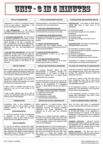
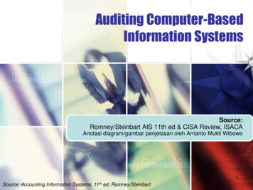
Floating pointrepresentation.docxError Detectingcodes.docxError Detection codes:Information is stored as binary codes and are transmitted by serial or parallel communication. Duringtransmission noise is added to the signal and it may change binary bits in the code from 1 to 0, and viceversa. An error detection code is a binary code that detects digital errors during transmission. Thedetected errors can not be corrected but their presence is indicated.Parity bit:The most common error detection code used is the parity bit. A parity bit is an extra bit included with abinary message to make the total number of 1’s either odd or even. If the message consists of n bits ,then the error detection code consists of n 1 bits. If the bit added to the message makes the sum of 1’sodd in the error detection code, then the scheme is called odd-parity. If the sum of bits is even , thescheme is called even parity scheme.Message xyzP(odd)P(even)Error detectioncode, odd parityError detectioncode, even 1101111001
Parity Generator and Parity Checker:XYzodd Parity outParity Checker:XYzParity out from generatorErrorIndication
The circuit arrangement checks the occurrence of error any odd number of times. An even number oferrors is not detected.We note that P(even) function is the exclusive –OR x,y,z because it is equal to 1 when either one or all 3of the variables are equal to 1. The P(odd) function is the complement of the P(even) function.Assume at the sending end the message bits and odd parity bit is generated. The EX-OR gates generateP(even ) function and to generate P(odd), the complement of P(even) is used.The 4 bits transmitted has an odd number of I’s. If an error occurs during transmission, then the numberof 1’s become even. Hence parity checker checks for even parity.1.1.2.6.Lecture-6COMPUTER ARITHMETIC:Addition, subtraction, multiplication are the four basic arithmetic operations. Using these operationsother arithmetic functions can be formulated and scientific problems can be solved by numericalanalysis methods.Arithmetic Processor:It is the part of a processor unit that executes arithmetic operations. The arithmetic instructionsdefinitions specify the data type that should be present in the registers used . The arithmetic instructionmay specify binary or decimal data and in each case the data may be in fixed-point or floating pointform.Fixed point numbers may represent integers or fractions. The negative numbers may be in signedmagnitude or signed- complement representation. The arithmetic processor is very simple if only abinary fixed point add instruction is included. It would be more complicated if it includes all fourarithmetic operations for binary and decimal data in fixed and floating point representations.Algorithm:Algorithm can be defined as a finite number of well defined procedural steps to solve a problem.Usually, an algorithm will contain a number of procedural steps which are dependent on results ofprevious steps. A convenient method for presenting an algorithm is a flowchart which consists ofrectangular and diamond –shaped boxes. The computational steps are specified in the rectangularboxes and the decision steps are indicated inside diamond-shaped boxes from which 2 or morealternate path emerge.Addition and Subtraction:3 ways of representing negative fixed point binary numbers:
1. Signed-magnitude representation---- used for the representation of mantissa for floating pointoperations by most computers.2. Signed-1’s complement3. Signed -2’s complement—Most computers use this form for performing arithmetic operationwith integersAddition and subtraction algorithm for signed-magnitude dataLet the magnitude of two numbers be A & B. When signed numbers are added or subtracted,there are 4 different conditions to be considered for each addition and subtraction dependingon the sign of the numbers. The conditions are listed in the table below. The table shows theoperation to be performed with magnitude(addition or subtraction) are indicated for tract magnitudesWhen A BWhen A BWhen A B1( A ) ( B ) (A B)2( A ) (-B ) ( A-B )-( B-A ) ( A-B )3( -A ) ( B )-( A-B ) ( B-A ) ( A-B )4( -A ) (-B )5( A ) - ( B ) ( A-B )-( B-A ) ( A-B )6( A ) - (-B ) (A B)7( -A ) - ( B )-(A B)8( -A ) - (-B )-( A-B ) ( B-A ) ( A-B )-(A B)The last column is needed to prevent a negative zero. In other words, when two equal numbersare subtracted, the result should be 0 not -0.The algorithm for addition and subtraction ( from the table above):Addition Algorithm:When the signs of A and B are identical, add two magnitudes and attach the sign of A to theresult. When the sign of A and B are different, compare the magnitudes and subtract thesmaller number from the larger. Choose the sign of the result to be the same as A if A B or the
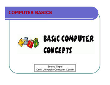
complement of sign of A if A B. If the two magnitudes are equal, subtract B from A and makete sign of the result positive.Subtraction algorithm:When the signs of A and B are different, add two magnitudes and attach the sign of A to theresult. When the sign of A and B are identical, compare the magnitudes and subtract thesmaller number from the larger. Choose the sign of the result to be the same as A if A B or thecomplement of sign of A if A B. If the two magnitudes are equal, subtract B from A and makete sign of the result positive.Hardware Implementation:Let A and B are two registers that hold the numbers.AS and BS are 2, flip-flops that hold sign of corresponding numbers. The result is stored In A andAS .and thus they form Accumulator register.We need to perform micro operation, A B and hence a parallel adder.A comparator is needed to establish if A B, A B, or A B.We need to perform micro operations A-B and B-A and hence two parallel subtractor.An exclusive OR gate can be used to determine the sign relationship, that is, equal or not.Thus the hardware components required are a magnitude comparator, an adder, and twosubtractors.Reduction of hardware by using different procedure:1. We know subtraction can be done by complement and add.2. The result of comparison can be determined from the end carry after the subtraction.We find An adder and a complementer can do subtraction and comparison if 2’scomplement is used for subtraction.Hardware forsigned-magnitude addition and subtraction:AVF Add overflow flip flop. It hold the overflow bit when A & B are added.
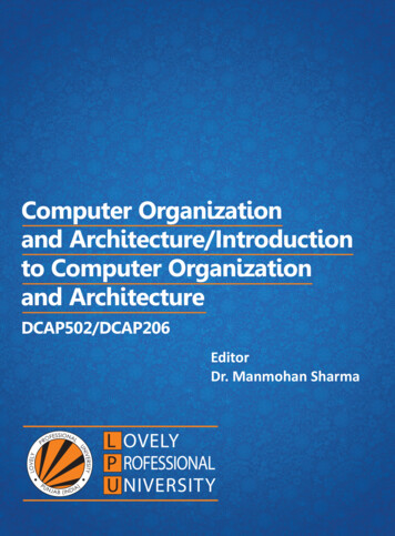
Flip flop E—Output carry is transferred to E. It can be checked to see the relative magnitudes of the twonumbers.A-B A ( -B ) Adding a and 2’s complement of B.The A register provides other micro operations that may be needed when the sequence of steps in thealgorithm is specified.The complementer Passes the contents of B or the complement of B to the Parallel Adder depending onthe state of the mode control B. It consists of EX-OR gates and the parallel adder consists of full addercircuits. The M signal is also applied to the input carry of the adder.When input carry M 0, the sum of full adder is A B. When M 1, S A B’ 1 A – BHardware algorithm:Flow Chart for Add and Subtract operations:The EX-OR gate provides 0 as output when the signs are identical. It is 1 when the signs are different.A B is computed for the following and the sum is stored in EA:1. When the signs are same and addition operation is required.2. When the signs are different and subtract operation is required.The carry in E after addition indicates an overflow if it is 1 and it is transferred to AVF, theaddoverflow flagA-B A B’ 1 computed for the following:1. When the signs are different and addition operation is required.2. When the signs are same and subtract operation is required.No overflow can occur if the numbers are subtracted and hence AVF is cleared to Zero.[ the subtraction of 2 n-digit un signed numbers M-N ( N 0) in base r can be done as follows:1.2.Add minuend M to thee r’s complement of the subtrahend N. This performs M-N rn .If M N, The sum will produce an end carry rnwhich is discarded, and what is left is the result M-N.3.If M N, the sum does not produce an end carry and is equal to rn–( N-M ), which is the r’s complement of the sum and place a negativesign in front.]A 1 in E indicates that A B and the number in A is the correct result.If this number in A is zero, the sign AS must be made positive to avoid a negative zero.A 0 in E indicates that A B. For this case it is necessary to take the 2’s complement ofthe value in A.In the algorithm shown in flow chart, it is assumed that A register has circuits for microoperations complement and increment. Hence two complement of value in A isobtained in 2, micro operations. In other paths of the flow chart , the sign of the result isthe same as the sign of A, so no change in AS is required.
However When A B, the sign of the result is the complement of original sign of A.Hence The complement of AS stored in AS.Final Result: AS AFlow chart for ADD and Subtract operations:Addition and Subtraction with signed-2’s complement Data.:Arithmetic Addition:This method does not need a comparison or subtraction but only addition andcomplementation. The procedure is as below:1. Represent the negative numbers in 2’s complement form.2. Add the two numbers including the sign bits and discard any carry out of sign bitposition.3. The overflow bit V is set to 1 if there is a carry into sign bit and no carry out of signbit or if there is a no carry into sign bit and a carry out of sign bit. Otherwise it isset to zero.4. If the result is negative, take the 2’s complement of the result to get a correctnegative result.Arithmetic Subtraction:1. Represent the negative numbers in 2’s complement form.
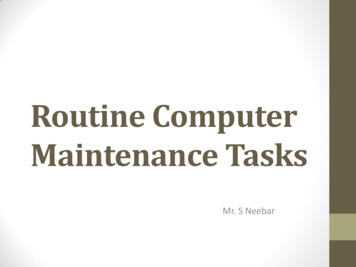
2. Take the 2’s complement of the subtrahend including the sign bit and add it to theminuend including the sign bit.3. The overflow bit V is set to 1 if there is a carry into sign bit and no carry out of signbit or if there is a no carry into sign bit and a carry out of sign bit. Otherwise it isset to zero.4. Discard the carry out of the sign bit position.Note: A subtraction operation can be changed to an addition operation if the sign of the subtrahend ischanged.BR RegisterVComplementer&Parallel AdderOverflowAC RegisterFig: Hardware for Signed 2/s complement for addition/ subtractioin.lecture-6.docx
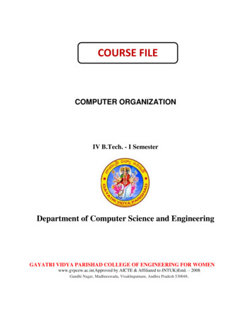
1.1.2.7.Lecture-7Multiplication Algorithm:Hardware implementation of multiplication of numbers in signed – magnitude form:1. A adder is provided to add two binary numbers and the partial product is accumulated in a register.2. Instead of shifting the multiplicand to the left, the partial product is shifted to the right, which resultin leaving the partial product and the multiplicand in the required relative positions.3. When the corresponding bit of the multiplier is zero, there is no need to add all zeros to the partialproduct, since it will not alter it’s value.The hardware consists of 4 flipflops, 3 registers, one sequence counter , an adder and complementer.Q register&QS flip flop: contains multiplier & Its signSequence counter:It is set to a value equal to the number of bits in the multiplierB Register& BS flipflop:It contains the multiplicand,& its signA Register, E Flip flop: Initialized to ‘ 0’. AS denotes sign of partial productEA Register: hold partial product, with carry generated in addition being shifted to E .Qn: Rightmost bit of the multiplier; AQ : will contain the final product.As AQ represent product register, both AS QSrepresent the sign of the partial product or product.The number to be multiplied are stores in memory as n bit sign magnitude numbers and whentransferred to register msb bit go to sign flipflop and remaining n-1 bits go to registers. Hence SC isinitially set to n-1.Let the lower order bit of the multiplier in Qntested.If it is 1, the multiplicand in B is added to the present partial product in A.If it is a ‘0’, nothing is done. Register EAQ is then shifted once to the right to form the new partialproduct. The sequence counter is decremented by 1 and it’s new value checked. If it is not equal tozero, the process is repeated and a new partial product is formed. The process stops when SC 0.
The final product is available in both A and Q, with A holding the most significant bits and Q holding theleast significant bits.Flowchart for multiply operation:Numerical Example for the above algorithm:Multiplicand B 10111EAQSCMultiplier in Q0000001001110111001100Qn 1;add B10111First Partial Product010111Shift Right EAQ001011Qn 1;add BSecond Partial Product10111100010
Shift Right EAQ01000101100011Qn 0; Shift Right EAQ00100010110010Qn 0; Shift Right EAQ0001000101100110101000Qn 1;add B10111Fifth Partial Product011011Shift Right EAQ001101Final Product in AQAQ 0110110101lecture-7.docx1.1.2.8. Lecture-8Booth Multiplication Algorithm:Multiplication of signed- 2’s complement integers:This algorithm uses the following facts.1. A string of 0’s in the multiplier requires no addition but just shifting.2. A string of 1’s in the multiplier from bit weight 2k to weight 2m can be treated as 2k 1 - 2m.Example: Consider the binary number: 001110( 14 )The number has a string of 1’s from 23 to 21 . Hence k 3 and m 1. As other bits are 0’s, thenumber can be represented as 2k 1 - 2m 24 – 21 16-2 14. Therefore the multiplication M * 14 ,where M is the multiplicand and 14 the multiplier can be done as Mx 24 –M x 21.This can be achieved by shifting binary multiplicand M four times to the left and subtracting Mshifted left once which is equal to (Mx 24 –M x 21
Computer Architecture and Organization-John P.Hayes ,McGraw Hill, International editions,2002. Lecture Plan Lecture no. Unit Number Topic 1. I Introduction to Computer architecture and Organization 2. I Computer Types, functional Units and Basic Operational Concepts, Bus structure, so