Transcription
Computer Organization and ArchitectureChapter 5 : Computer ArithmeticChapter – 5Computer ArithmeticInteger Representation: (Fixed-point representation):An eight bit word can be represented the numbers from zero to 255 including00000000 000000001 1------11111111 255In general if an n-bit sequence of binary digits an-1, an-2 .a1, a0; is interpreted as unsignedinteger A.n 1A i 02iaiSign magnitude representation:There are several alternative convention used to represent negative as well as positive integers,all of which involves treating the most significant (left most) bit in the word as sign bit. If thesign bit is 0, the number is ve and if the sign bit is 1, the number is –ve. In n bit word the rightmost n-1 bit hold the magnitude of integer.For an example, 18 00010010- 18 10010010 (sign magnitude)The general case can be expressed as follows:n 2A i 0n 22iaiif an-1 0 - 2iai if an-1 1i 0A -2n-1 an-1 n 2 i 02iai(Both for ve and –ve)There are several drawbacks to sign-magnitude representation. One is that addition or subtractionrequires consideration of both signs of number and their relative magnitude to carry out therequired operation. Another drawback is that there are two representation of zero. For anexample: 010 00000000-010 10000000 this is inconvenient.2’s complement representation:Like sign magnitude representation, 2’s complement representation uses the most significant bitas sign bit making it easy to test whether the integer is negative or positive. It differs from theuse of sign magnitude representation in the way that the other bits are interpreted. For negation,take the Boolean complement (1’s complement) of each bit of corresponding positive number,and then add one to the resulting bit pattern viewed as unsigned integer. Consider n bit integer Ain 2’s complement representation. If A is ve then the sign bit an-1 is zero. The remaining bitsrepresent the magnitude of the number.Compiled By: Er. Hari Aryal [haryal4@gmail.com]Reference: W. Stallings 1
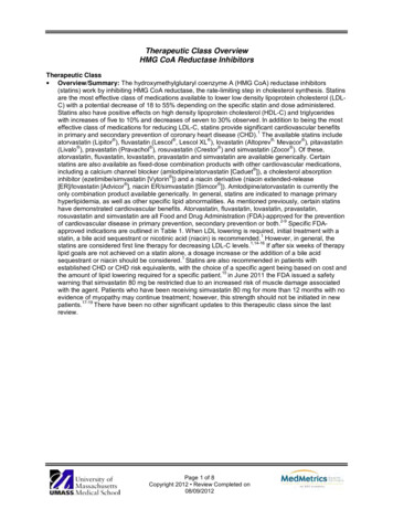
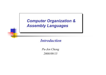
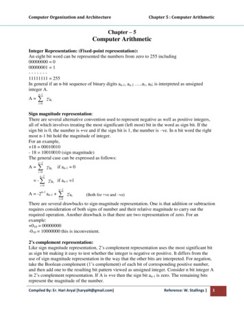
Computer Organization and Architecturen 2A i 02iaiChapter 5 : Computer Arithmeticfor A 0The number zero is identified as ve and therefore has zero sign bit and magnitude of all 0’s. Wecan see that the range of ve integer that may be represented is from 0 (all the magnitude bitsare zero) through 2n-1-1 (all of the magnitude bits are 1).Now for –ve number integer A, the sign bit an-1 is 1. The range of –ve integer that can berepresented is from -1 to -2n-12’s complement, A -2n-1 an-1 n 2 i 02iaiDefines the twos complement of representation of both positive and negative number.For an example: 18 000100101’s complement 111011012’s complement 11101110 -185.15.2Addition AlgorithmSubtraction Algorithm1001 -70101 51110 -21100 -40100 410000 00011 30100 40111 7(a) (-7) ( 5)(b) (-4) (4)(c) ( 3) ( 4)1100 -41111 -111011 -50101 50100 41001 overflow1001 -71010 -610011 overflow(d) (-4) (-1)(e) ( 5) ( 4)(f) (-7) (-6)The first four examples illustrate successful operation if the result of the operation is ve then weget ve number in ordinary binary notation. If the result of the operation is –ve we get negativenumber in twos complement form. Note that in some instants there is carry bit beyond the end ofwhat which is ignored. On any addition the result may larger then can be held in word size beinguse. This condition is called over flow. When overflow occur ALU must signal this fact so thatno attempt is made to use the result. To detect overflow the following rule observed. If twonumbers are added, and they are both ve or both –ve; then overflow occurs if and only if theresult has the opposite sign.The data path and hardware elements needed to accomplish addition and subtraction is shown infigure below. The central element is binary adder, which is presented two numbers for additionand produces a sum and an overflow indication. The binary adder treats the two numbers asunsigned integers. For addition, the two numbers are presented to the adder from two registers Aand B. The result may be stored in one of these registers or in the third. The overflow indicationis stored in a 1-bit overflow flag V (where 1 overflow and 0 no overflow). For subtraction,the subtrahend (B register) is passed through a 2’s complement unit so that its 2’s complement ispresented to the adder (a – b a (-b)).Compiled By: Er. Hari Aryal [haryal4@gmail.com]Reference: W. Stallings 2
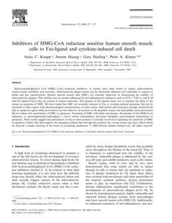
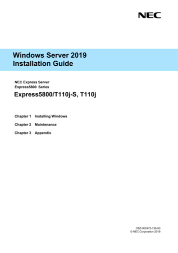
Computer Organization and ArchitectureB RegisterChapter 5 : Computer ArithmeticA RegisterComplementSwitchB7XORn bit AdderB8VZSC/ n bitB7Check for ZeroFig: Block diagram of hardware for addition / subtraction5.3Multiplication AlgorithmThe multiplier and multiplicand bits are loaded into two registers Q and M. A third register A isinitially set to zero. C is the 1-bit register which holds the carry bit resulting from addition. Now,the control logic reads the bits of the multiplier one at a time. If Q0 is 1, the multiplicand is addedto the register A and is stored back in register A with C bit used for carry. Then all the bits ofCAQ are shifted to the right 1 bit so that C bit goes to An-1, A0 goes to Qn-1 and Q0 is lost. If Q0 is0, no addition is performed just do the shift. The process is repeated for each bit of the originalmultiplier. The resulting 2n bit product is contained in the QA register.Fig: Block diagram of multiplicationCompiled By: Er. Hari Aryal [haryal4@gmail.com]Reference: W. Stallings 3
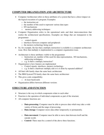
Computer Organization and ArchitectureChapter 5 : Computer ArithmeticThere are three types of operation for multiplication. It should be determined whether a multiplier bit is 1 or 0 so that it can designate thepartial product. If the multiplier bit is 0, the partial product is zero; if the multiplier bit is1, the multiplicand is partial product. It should shift partial product. It should add partial product.Unsigned Binary Multiplication1011 Multiplicand 11X 1101 Multiplier 1310110000Partial Product1011 101110001111 Product (143)StartM ß Multiplicand, Q ß MultiplierC, A ß 0, Count ß No. of bits of QNoIsQ0 1?YesAßA MRight Shift C, A, QCount ß Count - 1NoIsCount 0?YesStopResult in AQFig. : Flowchart of Unsigned Binary MultiplicationCompiled By: Er. Hari Aryal [haryal4@gmail.com]Reference: W. Stallings 4
Computer Organization and ArchitectureChapter 5 : Computer ArithmeticExample: Multiply 15 X 11 using unsigned binary 001111011110111101-3Add (A ß A M)Logical Right Shift C, A, Q100110101111010110-2Add (A ß A M)Logical Right Shift C, A, Q001011011-1Logical Right Shift C, A, Q100100101010110101-0Add (A ß A M)Logical Right Shift C, A, QResult 1010 0101 27 25 22 20 165Alternate Method of Unsigned Binary MultiplicationStartX ß Multiplicand, Y ß MultiplierSum ß 0, Count ß No. of bits of YNoIsY0 1?YesSum ß Sum XLeft Shift X, RightShift YCount ß Count - 1NoIsCount 0?YesStopResult in SumFig: Unsigned Binary Multiplication Alternate methodCompiled By: Er. Hari Aryal [haryal4@gmail.com]Reference: W. Stallings 5
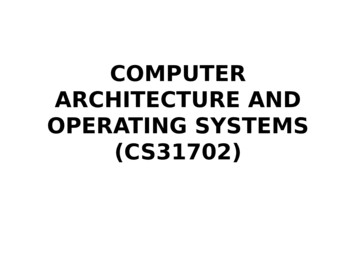
Computer Organization and ArchitectureChapter 5 : Computer ArithmeticAlgorithm:Step 1: Clear the sum (accumulator A). Place the multiplicand in X and multiplier in Y.Step 2: Test Y0; if it is 1, add content of X to the accumulator A.Step 3: Logical Shift the content of X left one position and content of Y right one position.Step 4: Check for completion; if not completed, go to step 2.Example: Multiply 7 X 00000011100112Left shift X, Right Shift Y00111001110000111010101110000000Sum ß Sum X,Left shift X, Right Shift YSum ß Sum X,Left shift X, Right Shift YResult 101010 25 23 21 42Signed Multiplication (Booth Algorithm) – 2’s Complement MultiplicationMultiplier and multiplicand are placed in Q and M register respectively. There is also one bitregister placed logically to the right of the least significant bit Q0 of the Q register and designatedas Q-1. The result of multiplication will appear in A and Q resister. A and Q-1 are initialized tozero if two bits (Q0 and Q-1) are the same (11 or 00) then all the bits of A, Q and Q-1 registers areshifted to the right 1 bit. If the two bits differ then the multiplicand is added to or subtracted fromthe A register depending on weather the two bits are 01 or 10. Following the addition orsubtraction the arithmetic right shift occurs. When count reaches to zero, result resides into AQin the form of signed integer [-2n-1*an-1 2n-2*an-2 21*a1 20*a0].Compiled By: Er. Hari Aryal [haryal4@gmail.com]Reference: W. Stallings 6
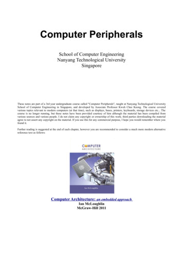
Computer Organization and ArchitectureChapter 5 : Computer ArithmeticStartInitialize A ß 0, Q-1 ß 0,M ß Multiplicand, Q ß Multiplier,Count ß No. of bits of QAßA-M 10IsQ0Q-1? 01AßA M 11 00Arithmetic Shift RightA, Q, Q-1Count ß Count - 1NoIsCount 0?YesStopResult in AQFig.: Flowchart of Signed Binary Numbers (using 2’s Complement, Booth Method)Example: Multiply 9 X -3 -27 using Booth Algorithm 3 00011, -3 11101 (2’s complement of 3)AQQ-1 Add (M) Sub ( M 1) 11111011111011111001--4Sub (A ß A - M) as Q0Q-1 10Arithmetic Shift Right A, Q, Q-10010000010111100111110--3Add (A ß A M) as Q0Q-1 01Arithmetic Shift Right A, Q, Q-11100111100011111011101--2Sub (A ß A - M) as Q0Q-1 10Arithmetic Shift Right A, Q, Q-111110010111--1Arithmetic Shift Right A, Q, Q-1as Q0Q-1 11111110010110Arithmetic Shift Right A, Q, Q-1as Q0Q-1 119876520Result in AQ 11111 00101 -2 2 2 2 2 2 2 -512 256 128 64 32 4 1 -27Compiled By: Er. Hari Aryal [haryal4@gmail.com]Reference: W. Stallings 7
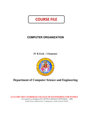
Computer Organization and ArchitectureChapter 5 : Computer Arithmetic5.4Division AlgorithmDivision is somewhat more than multiplication but is based on the same general principles. Theoperation involves repetitive shifting and addition or subtraction.First, the bits of the dividend are examined from left to right, until the set of bits examinedrepresents a number greater than or equal to the divisor; this is referred to as the divisor beingable to divide the number. Until this event occurs, 0s are placed in the quotient from left to right.When the event occurs, a 1 is placed in the quotient and the divisor is subtracted from the partialdividend. The result is referred to as a partial remainder. The division follows a cyclic pattern.At each cycle, additional bits from the dividend are appended to the partial remainder until theresult is greater than or equal to the divisor. The divisor is subtracted from this number toproduce a new partial remainder. The process continues until all the bits of the dividend areexhausted.Shift LeftAnAn-1 A0Add / SubtractQn-1 Q0Control UnitN 1 BitAdder0Mn-1 M0 DivisorFig.: Block Diagram of Division OperationCompiled By: Er. Hari Aryal [haryal4@gmail.com]Reference: W. Stallings 8
Computer Organization and ArchitectureChapter 5 : Computer ArithmeticRestoring Division (Unsigned Binary Division)Algorithm:Step 1: Initialize A, Q and M registers to zero, dividend and divisor respectively and counter to nwhere n is the number of bits in the dividend.Step 2: Shift A, Q left one binary position.Step 3: Subtract M from A placing answer back in A. If sign of A is 1, set Q0 to zero and add Mback to A (restore A). If sign of A is 0, set Q0 to 1.Step 4: Decrease counter; if counter 0, repeat process from step 2 else stop the process. Thefinal remainder will be in A and quotient will be in Q.Compiled By: Er. Hari Aryal [haryal4@gmail.com]Reference: W. Stallings 9
Computer Organization and ArchitectureExample: Divide 15 (1111) by 4 (0100)AQMM 10000011110010011100Chapter 5 : Computer 01111 111 1110--3Shift Left A, QSub (A ß A – M)Q0 ß 0, Add (Aß A M)000111111100011110 110 1100--2Shift Left A, QSub (A ß A – M)Q0 ß 0, Add (Aß A M)001110001100011100 100 1001--1Shift Left A, QSub (A ß A – M)Set Q0 ß 100111001 00011001 000110011Quotient in Q 0011 3Remainder in A 00011 3-0Shift Left A, QSub (A ß A – M)Set Q0 ß 1Non – Restoring Division (Signed Binary Division)AlgorithmStep 1: Initialize A, Q and M registers to zero, dividend and divisor respectively and count tonumber of bits in dividend.Step 2: Check sign of A;If A 0 i.e. bn-1 is 1a. Shift A, Q left one binary position.b. Add content of M to A and store back in A.If A 0 i.e. bn-1 is 0a. Shift A, Q left one binary position.b. Subtract content of M to A and store back in A.Step 3: If sign of A is 0, set Q0 to 1 else set Q0 to 0.Step 4: Decrease counter. If counter 0, repeat process from step 2 else go to step 5.Step 5: If A 0 i.e. positive, content of A is remainder else add content of M to A to get theremainder. The quotient will be in Q.Compiled By: Er. Hari Aryal [haryal4@gmail.com]Reference: W. Stallings 10
Computer Organization and ArchitectureChapter 5 : Computer ArithmeticStartInitialize: A ß 0, M ß Divisor,Q ß Dividend, Count ß No. of bits of QLeft Shift AQIsA 0?NoYesAßA MQ0 ß 1Left Shift AQAßA-MIsA 0?NoYesQ0 ß 0Count ß Count - 1YesIsCount 0?NoYesIsA 0?StopCompiled By: Er. Hari Aryal [haryal4@gmail.com]NoAßA MQuotient in QRemainder in AReference: W. Stallings 11
Computer Organization and ArchitectureChapter 5 : Computer ArithmeticExample: Divide 1110 (14) by 0011 (3) using non-restoring division.AQMCountM 1011110110 110 1100--3Shift Left A, QSub (A ß A – M)Set Q0 to 0111010000000000100 100 1001--2Shift Left A, QAdd (A ß A M)Set Q0 to 1000011111011110001 001 0010--1Shift Left A, QSub (A ß A – M)Set Q0 to 011100010 11111010 111110100000100100Quotient in Q 0011 3Remainder in A 00010 2-0-Shift Left A, QAdd (A ß A M)Set Q0 to 0Add (A ß A M)Compiled By: Er. Hari Aryal [haryal4@gmail.com]Reference: W. Stallings 12
Computer Organization and ArchitectureChapter 5 : Computer ArithmeticFloating Point RepresentationThe floating point representation of the number has two parts. The first part represents a signedfixed point numbers called mantissa or significand. The second part designates the position ofthe decimal (or binary) point and is called exponent. For example, the decimal no 6132.789 isrepresented in floating point with fraction and exponent as follows.FractionExponent 0.6132789 04This representation is equivalent to the scientific notation 0.6132789 10 4The floating point is always interpreted to represent a number in the following form M R E.Only the mantissa M and the exponent E are physically represented in the register (includingtheir sign). The radix R and the radix point position of the mantissa are always assumed.A floating point binary no is represented in similar manner except that it uses base 2 for theexponent.For example, the binary no 1001.11 is represented with 8 bit fraction and 0 bit exponent asfollows.0.1001110 2100FractionExponent01001110000100The fraction has zero in the leftmost position to denote positive. The floating point number isequivalent to M 2E (0.1001110)2 2 4Floating Point ArithmeticThe basic operations for floating point arithmetic areFloating point numberArithmetic OperationsXEX Xs BX Y (Xs BXE-YE Ys) BYEYEY Ys BX - Y (Xs BXE-YE - Ys) BYEX * Y (Xs Ys) BXE YEX / Y (Xs / Ys) BXE-YEThere are four basic operations for floating point arithmetic. For addition and subtraction, it isnecessary to ensure that both operands have the same exponent values. This may require shiftingthe radix point on one of the operands to achieve alignment. Multiplication and division arestraighter forward.A floating point operation may produce one of these conditions: Exponent Overflow: A positive exponent exceeds the maximum possible exponent value. Exponent Underflow: A negative exponent which is less than the minimum possiblevalue. Significand Overflow: The addition of two significands of the same sign may carry in acarry out of the most significant bit. Significand underflow: In the process of aligning significands, digits may flow off theright end of the significand.Compiled By: Er. Hari Aryal [haryal4@gmail.com]Reference: W. Stallings 13
Computer Organization and ArchitectureChapter 5 : Computer ArithmeticFloating Point Addition and SubtractionIn floating point arithmetic, addition and subtraction are more complex than multiplication anddivision. This is because of the need for alignment. There are four phases for the algorithm forfloating point addition and subtraction.1. Check for zeros:Because addition and subtraction are identical except for a sign change, the processbegins by changing the sign of the subtrahend if it is a subtraction operation. Next; if oneis zero, second is result.2. Align the Significands:Alignment may be achieved by shifting either the smaller number to the right (increasingexponent) or shifting the large number to the left (decreasing exponent).3. Addition or subtraction of the significands:The aligned significands are then operated as required.4. Normalization of the result:Normalization consists of shifting significand digits left until the most significant bit isnonzero.Example: AdditionX 0.10001 * 2110Y 0.101 * 2100Since EY EX, Adjust YY 0.00101 * 2100 * 2010 0.00101 * 2110So, EZ EX EY 110Now, MZ MX MY 0.10001 0.00101 0.10110Hence, Z MZ * 2EZ 0.10110 * 2110Example: SubtractionX 0.10001 * 2110Y 0.101 * 2100Since EY EX, Adjust YY 0.00101 * 2100 * 2010 0.00101 * 2110So, EZ EX EY 110Now, MZ MX - MY 0.10001 - 0.00101 0.01100Z MZ * 2EZ 0.01100 * 2110 (Un-Normalized)Hence, Z 0.1100 * 2110 * 2-001 0.1100 * 2101Compiled By: Er. Hari Aryal [haryal4@gmail.com]Reference: W. Stallings 14
Computer Organization and ArchitectureChapter 5 : Computer ArithmeticStartIsX 0?Zß YStopIsY 0?Adjust X such that:EZ EX EYEX EYZß XEY EXCheckthe exponent?Adjust Y such that:EZ EX EYEY EXAdjust the MantissaMZ MX MYForm the floatingpoint numberZ MZ * 2EZIs½ MZ 1?NoPost NormalizeYesStopCompiled By: Er. Hari Aryal [haryal4@gmail.com]Reference: W. Stallings 15
Computer Organization and ArchitectureChapter 5 : Computer ArithmeticFloating Point MultiplicationThe multiplication can be subdivided into 4 parts.1. Check for zeroes.2. Add the exponents.3. Multiply mantissa.4. Normalize the product.Example:X 0.101 * 2110Y 0.1001 * 2-010As we know, Z X * Y (MX * MY) * 2(EX EY)Z (0.101 * 0.1001) * 2(110-010) 0.0101101 * 2100 0.101101 * 2011 (Normalized)Compiled By: Er. Hari Aryal [haryal4@gmail.com]0.1001* 0.10110010000* 1001**101101 0.0101101Reference: W. Stallings 16
Computer Organization and ArchitectureChapter 5 : Computer ArithmeticFloating Point DivisionThe division algorithm can be subdivided into 5 parts1. Check for zeroes.2. Initial registers and evaluates the sign.3. Align the dividend.4. Subtract the exponent.5. Divide the mantissa.Compiled By: Er. Hari Aryal [haryal4@gmail.com]Reference: W. Stallings 17
Computer Organization and ArchitectureChapter 5 : Computer ArithmeticExample:X 0.101 * 2110Y 0.1001 * 2-010As we know, Z X / Y (MX / MY) * 2(EX – EY)MX / MY 0.101 / 0.1001 (1/2 1/8) / (1/2 1/16) 1.11 1.000110.11 * 2 0.22 00.22 * 2 0.44 00.44 * 2 0.88 00.88 * 2 1.76 10.76 * 2 1.52 1EX – EY 110 010 1000Now, Z MZ * 2EZ 1.00011 * 21000 0.100011 * 210015.5Logical OperationGate Level Logical ComponentsCompiled By: Er. Hari Aryal [haryal4@gmail.com]Reference: W. Stallings 18
Computer Organization and ArchitectureChapter 5 : Computer ArithmeticComposite Logic GatesCompiled By: Er. Hari Aryal [haryal4@gmail.com]Reference: W. Stallings 19
Computer Organization and Architecture Chapter 5 : Computer Arithmetic Compiled By: Er. Hari Aryal [haryal4@gmail.com] Reference: W. Stallings 3 B R e g is te r A R e g is te r C omple me nt S w itc h n b i