Transcription
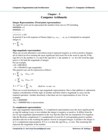
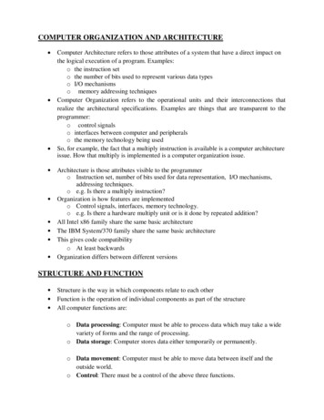
COMPUTER ORGANIZATION AND ARCHITECTURE Computer Architecture refers to those attributes of a system that have a direct impact onthe logical execution of a program. Examples: o the instruction set o the number of bits used to represent various data typeso I/O mechanisms o memory addressing techniques Computer Organization refers to the operational units and their interconnections thatrealize the architectural specifications. Examples are things that are transparent to theprogrammer: o control signals o interfaces between computer and peripheralso the memory technology being used So, for example, the fact that a multiply instruction is available is a computer architectureissue. How that multiply is implemented is a computer organization issue. Architecture is those attributes visible to the programmero Instruction set, number of bits used for data representation, I/O mechanisms,addressing techniques.o e.g. Is there a multiply instruction?Organization is how features are implementedo Control signals, interfaces, memory technology.o e.g. Is there a hardware multiply unit or is it done by repeated addition?All Intel x86 family share the same basic architectureThe IBM System/370 family share the same basic architectureThis gives code compatibilityo At least backwardsOrganization differs between different versionsSTRUCTURE AND FUNCTION Structure is the way in which components relate to each otherFunction is the operation of individual components as part of the structureAll computer functions are:o Data processing: Computer must be able to process data which may take a widevariety of forms and the range of processing.o Data storage: Computer stores data either temporarily or permanently.o Data movement: Computer must be able to move data between itself and theoutside world.o Control: There must be a control of the above three functions.
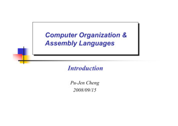
Fig: Functional view of a computerFig: Data movement operation Fig: Processing from / to storageFour main structural components:Fig: Storage OperationFig: Processing from storage to i/oo Central processing unit (CPU)
o Main memoryo I/Oo System interconnectionsCPU structural components:o Control unito Arithmetic and logic unit (ALU)o Registerso CPU interconnections itMemorySystemsInterconnectionCommunication linesFig: Computer: Top level ersSystemLogin UnitCPUBusandInternal CPUMemoryInterconnectionControl unitFig: The central processing unit
Control UnitCPUSequencingALUInternalControlLoginControl UnitBusUnitRegistersRegisters andDecodersControlFig: The control unitMemoryCOMPUTER COMPONENTS The Control Unit (CU) and the Arithmetic and Logic Unit (ALU) constitute the CentralProcessing Unit (CPU)Data and instructions need to get into the system and results need to get outo Input/output (I/O module)Temporary storage of code and results is neededo Main memory (RAM)Program Concepto Hardwired systems are inflexibleo General purpose hardware can do different tasks, given correct control signalso Instead of re-wiring, supply a new set of control signals
COMPUTER FUNCTIONThe basic function performed by a computer is execution of a program, which consists of a set ofinstructions stored in memory. Two steps of Instructions Cycle:o Fetcho ExecuteFig: Basic Instruction Cycle Fetch Cycleo Program Counter (PC) holds address of next instruction to fetcho Processor fetches instruction from memory location pointed to by PCo Increment PCUnless told otherwiseo Instruction loaded into Instruction Register (IR) Execute Cycleo Processor interprets instruction and performs required actions, such as:Processor - memoryo data transfer between CPU and main memoryProcessor - I/Oo Data transfer between CPU and I/O moduleData processingo Some arithmetic or logical operation on dataControlo Alteration of sequence of operationso e.g. jumpCombination of above
Fig: Example of program execution (consists of memory and registers in hexadecimal) The PC contains 300, the address of the first instruction. The instruction (the value 1940in hex) is loaded into IR and PC is incremented. This process involves the use of MARand MBR. The first hexadecimal digit in IR indicates that the AC is to be loaded. The remainingthree hexadecimal digits specify the address (940) from which data are to be loaded. The next instruction (5941) is fetched from location 301 and PC is incremented. The old contents of AC and the contents of location 941 are added and the result is storedin the AC. The next instruction (2941) is fetched from location 302 and the PC is incremented. The contents of the AC are stored in location 941.Fig: Instruction cycle state diagramBUS INTERCONNECTION A bus is a communication pathway connecting two or more devicesUsually broadcast (all components see signal)Often groupedo A number of channels in one buso e.g. 32 bit data bus is 32 separate single bit channelsPower lines may not be shownThere are a number of possible interconnection systemsSingle and multiple BUS structures are most commone.g. Control/Address/Data bus (PC)e.g. Unibus (DEC-PDP)Lots of devices on one bus leads to:o Propagation delayso Long data paths mean that co-ordination of bus use can adversely affectperformanceo If aggregate data transfer approaches bus capacityMost systems use multiple buses to overcome these problems
Data Buso Carries data Remember that there is no difference between “data” and “instruction” at thislevel o Width is a key determinant of performance8, 16, 32, 64 bitAddress Buso Identify the source or destination of datao e.g. CPU needs to read an instruction (data) from a given location in memoryp Bus width determines maximum memory capacity of systeme.g. 8080 has 16 bit address bus giving 64k address spaceControl Busq Control and timing informationMemory readMemory writeI/O readI/O writeTransfer ACKBus requestBus grantInterrupt requestInterrupt ACKClockResetMultiple Bus Hierarchies A great number of devices on a bus will cause performance to suffer o Propagation delay - the time it takes for devices to coordinate the use of the buso The bus may become a bottleneck as the aggregate data transfer demand approachesthe capacity of the bus (in available transfer cycles/second)Traditional Hierarchical Bus Architecture o Use of a cache structure insulates CPU from frequent accesses to main memoryo Main memory can be moved off local bus to a system buso Expansion bus interfacebuffers data transfers between system bus and I/O controllers on expansion businsulates memory-to-processor traffic from I/O traffic
Traditional Hierarchical Bus Architecture ExamplePCI PCI is a popular high bandwidth, processor independent bus that can function as mezzanineor peripheral bus. PCI delivers better system performance for high speed I/O subsystems (graphic displayadapters, network interface controllers, disk controllers etc.) PCI is designed to support a variety of microprocessor based configurations including bothsingle and multiple processor system. It makes use of synchronous timing and centralised arbitration scheme. PCI may be configured as a 32 or 64-bit bus. Current Standard o up to 64 data lines at 33Mhzo requires few chips to implemento supports other buses attached to PCI buso public domain, initially developed by Intel to support Pentium-based systemso supports a variety of microprocessor-based configurations, including multipleprocessorso uses synchronous timing and centralized arbitration
Note: Bridge acts as a data buffer so that the speed of the PCI bus may differ from that of the processor’sI/O capability.PCI Bus Lines Systems lineso Including clock and resetAddress & Datao 32 time mux lines for address/datao Interrupt & validate linesInterface ControlArbitrationo Not sharedo Direct connection to PCI bus arbiterInterrupt lineso Not sharedCache support64-bit Bus Extensiono Additional 32 lineso Time multiplexedo 2 lines to enable devices to agree to use 64-bit transferJTAG/Boundary Scano For testing procedures
CPU REGISTERSIn computer architecture, a processor register is a very fast computer memory used to speed theexecution of computer programs by providing quick access to commonly used values-typically, the valuesbeing in the midst of a calculation at a given point in time.These registers are the top of the memory hierarchy, and are the fastest way for the system to manipulatedata. In a very simple microprocessor, it consists of a single memory location, usually calledan accumulator. Registers are built from fast multi-ported memory cell. They must be able to drive itsdata onto an internal bus in a single clock cycle. The result of ALU operation is stored here and could bere-used in a subsequent operation or saved into memory.Registers are normally measured by the number of bits they can hold, for example, an “8-bit register” or a“32-bit register”. Registers are now usually implemented as a register file, but they have also beenimplemented using individual flip-flops, high speed core memory, thin film memory, and other ways invarious machines.The term is often used to refer only to the group of registers that can be directly indexed for input oroutput of an instruction, as defined by the instruction set. More properly, these are called the “architectedregisters“. For instance, the x86 instruction set defines a set of eight 32-bit registers, but a CPU thatimplements the X86 instruction set will contain many more hardware registers than just these eight.There are several other classes of registers:(a) Accumulator: It is most frequently used register used to store data taken from memory. Its numbervaries from microprocessor to microprocessor.(b) General Purpose registers: General purpose registers are used to store data and intermediate resultsduring program execution. Its contents can be accessed through assembly programming.(c) Special purpose Registers: Users do not access these registers. These are used by computer system atthe time of program execution. Some types of special purpose registers are given below: Memory Address Register (MAR): It stores address of data or instructions to be fetched frommemory.Memory Buffer Register (MBR): It stores instruction and data received from the memory andsent from the memory.Instruction Register (IR): Instructions are stored in instruction register. When one instruction iscompleted, next instruction is fetched in memory for processing.Program Counter (PC): It counts instructions.
The instruction cycle is completed into two phases:(a) Fetch Cycle and(b) Execute Cycle.There are two parts in instruction- opcode and operand. In fetch cycle opcode of instruction is fetchedinto CPU. The opcode, at first, is reached to Data Register (DR), then to Instruction Register (IR).Decoder accesses the opcode and it decodes opcode and type of operation is declared to CPU andexecution cycle is started.INSTRUCTION FORMATSThe computer can be used to perform a specific task, only by specifying the necessary steps to completethe task. The collection of such ordered steps forms a ‘program’ of a computer. These ordered steps arethe instructions. Computer instructions are stored in central memory locations and are executedsequentially one at a time. The control reads an instruction from a specific address in memory andexecutes it. It then continues by reading the next instruction in sequence and executes it until thecompletion of the program. A computer usually has a variety of Instruction Code Formats. It is thefunction of the control unit within the CPU to interpret each instruction code and provide the necessarycontrol functions needed to process the instruction. An n bit instruction that k bits in the address field andm bits in the operation code field come addressed 2k location directly and specify 2m different operation The bits of the instruction are divided into groups called fields.The most common fields in instruction formats are:o An Operation code field that specifies the operation to be performed.o An Address field that designates a memory address or a processor register.o A Mode field that specifies the way the operand or the effective address is determined.n-1m-1k-10Fig: Instruction format with mode fieldThe operation code field (Opcode) of an instruction is a group of bits that define variousprocessor operations such as add, subtract, complement, shift etcetera. The bits that define themode field of an instruction code specify a variety of alternatives for choosing the operands fromthe given address. Operation specified by an instruction is executed on some data stored in theprocessor register or in the memory location. Operands residing in memory are specified by theirmemory address. Operands residing in processor register are specified with a register address.Types of Instruction Computers may have instructions of several different lengths containing varyingnumber of addresses.The number of address fields in the instruction format of a computer depends onthe internal organization of its registers.
Most computers fall into one of 3 types of CPU organizations:Single accumulator organization:- All the operations are performed with anaccumulator register. The instruction format in this type of computer uses one addressfield. For example: ADD X, where X is the address of the operands .General register organization:- The instruction format in this type of computer needsthree register address fields. For example: ADD R1,R2,R3Stack organization:- The instruction in a stack computer consists of an operation codewith no address field. This operation has the effect of popping the 2 top numbers from thestack, operating the numbers and pushing the sum into the stack. For example: ADDComputers may have instructions of several different lengths containing varying number ofaddresses. Following are the types of instructions.1. Three address InstructionWith this type of instruction, each instruction specifies two operand location and a resultlocation. A temporary location T is used to store some intermediate result so as not toalter any of the operand location. The three address instruction format requires a verycomplex design to hold the three address references.Format: Op X, Y, Z; X Y Op ZExample: ADD X, Y, Z; X Y Z ADVANTAGE: It results in short programs when evaluating arithmeticexpressions. DISADVANTAGE: The instructions requires too many bits to specify 3addresses.2. Two address instructionTwo-address instructions are the most common in commercial computers. Here againeach address field can specify either a processor register, or a memory word. One addressmust do double duty as both operand and result. The two address instruction formatreduces the space requirement. To avoid altering the value of an operand, a MOVinstruction is used to move one of the values to a result or temporary location T, beforeperforming the operation.Format: Op X, Y;X X Op YExample: SUB X, Y; X X - Y3. One address InstructionIt was generally used in earlier machine with the implied address been a CPU registerknown as accumulator. The accumulator contains one of the operand and is used to storethe result. One-address instruction uses an implied accumulator (Ac) register for all datamanipulation. All operations are done between the AC register and a memory operand.We use LOAD and STORE instruction for transfer to and from memory and Ac register.Format: Op X; Ac Ac Op XExample: MUL X; Ac Ac * X
4. Zero address InstructionIt does not use address field for the instruction like ADD, SUB, MUL, DIV etc. ThePUSH and POP instructions, however, need an address field to specify the operand thatcommunicates with the stack. The name “Zero” address is given because of the absenceof an address field in the computational instruction.Format: Op; TOS TOS Op (TOS – 1)Example: DIV; TOS TOS DIV (TOS – 1)Example: To illustrate the influence of the number of address on computer programs, we willevaluate the arithmetic statement X (A B)*(C D) using Zero, one, two, or three addressinstructions.1. Three-Address Instructions:ADD R1, A, B;R1 M[A] M[B]ADD R2, C, D;R2 M[C] M[D]MUL X, R1,R2;M[X] R1 * R2It is assumed that the computer has two processor registers R1 and R2. The symbol M[A]denotes the operand at memory address symbolized by A.2. Two-Address Instructions:MOV R1, A; R1 M[A]ADD R1, B; R1 R1 M[B]MOV R2, C; R2 M[C]ADD R2, D; R2 R2 M[D]MUL R1, R2; R1 R1 * R2MOV X, R1; M[X] R13. One-Address Instruction:LOAD A;Ac M[A]ADD B;Ac Ac M[B]STORE T;M[T] AcLOAD C;Ac M[C]ADD D;Ac Ac M[D]MUL T;Ac Ac * M[T]STORE X;M[X] AcHere, T is the temporary memory location required for storing the intermediate result.4. Zero-Address Instructions:PUSH A;TOS APUSH B;TOS BADD;TOS (A B)PUSH C;TOS CPUSH D;TOS DADD;TOS (C D)MUL;TOS (C D) * (A B)POP X ;M[X] TOS
ADDRESSING MODES Specifies a rule for interpreting or modifying the address field of the instruction beforethe operand is actually referenced.Computers use addressing mode techniques for the purpose of accommodating thefollowing purposes:o To give programming versatility to the user by providing such facilities aspointers to memory, counters for loop control, indexing of data and various otherpurposes.o To reduce the number of bits in the addressing field of the instructions. Other computers use a single binary for operation & Address mode. The mode field is used to locate the operand. Address field may designate a memory address or a processor register. There are 2 modes that need no address field at all (Implied & immediatemodes).Effective address (EA): The effective address is defined to be the memory address obtained from the computationdictated by the given addressing mode. The effective address is the address of the operand in a computational-type instruction.The most well known addressing mode are: Implied Addressing Mode. Immediate Addressing Mode Register Addressing Mode Register Indirect Addressing Mode Auto-increment or Auto-decrement Addressing Mode Direct Addressing Mode Indirect Addressing Mode Displacement Address Addressing Mode Relative Addressing Mode Index Addressing Mode Stack Addressing ModeImplied Addressing Mode: In this mode the operands are specified implicitly in the definition of the instruction.For example:- CMA - “complement accumulator” is an implied-mode instruction becausethe operand in the accumulator register is implied in the definition of the instruction. Infact, all register reference instructions that use an accumulator are e: no memory reference. Disadvantage: limited operandImmediate Addressing mode: In this mode the operand is specified in the instruction itself. In other words, an
immediate-mode instruction has an operand field rather than an address field. This instruction has an operand field rather than an address field. The operand fieldcontains the actual operand to be used in conjunction with the operation specified in theinstruction. These instructions are useful for initializing register to a constant value;For example MVI B, 50HInstructionOpcodeOperandIt was mentioned previously that the address field of an instruction may specify either a memoryword or a processor register. When the address field specifies a processor register, the instructionis said to be in register-mode.Advantage: no memory reference. Disadvantage: limited operandRegister direct addressing mode: In this mode, the operands are in registers that reside within the CPU. The particular register is selected from the register field in the instruction.For example MOV A, BInstructionOpcodeRegisterRegisterOperandEffective Address (EA) RAdvantage: no memory reference. Disadvantage: limited address spaceRegister indirect addressing mode: In this mode the instruction specifies a register in the CPU whose contents give theaddress of the operand in the memory. In other words, the selected register contains the address of the operand rather than theoperand itself. Before using a register indirect mode instruction, the programmer must ensure that thememory address of the operand is placed in the processor register with a previousinstruction.For example LDAX ective Address (EA) (R)Advantage: Large address space.
The address field of the instruction uses fewer bits to select a register than would have beenrequired to specify a memory address directly.Disadvantage: Extra memory referenceAuto increment or Auto decrement Addressing Mode: This is similar to register indirect mode except that the register is incremented ordecremented after (or before) its value is used to access memory. When the address stored in the registers refers to a table of data in memory, it isnecessary to increment or decrement the registers after every access to the table. This can be achieved by using the increment or decrement instruction. In some computersit is automatically accessed. The address field of an instruction is used by the control unit in the CPU to obtain theoperands from memory. Sometimes the value given in the address field is the address of the operand, butsometimes it is the address from which the address has to be calculated.Direct Addressing Mode In this mode the effective address is equal to the address part of the instruction. Theoperand resides in memory and its address is given directly by the address field of theinstruction.For example LDA e Address (EA) AAdvantage: Simple.Disadvantage: limited address fieldIndirect Addressing Mode In this mode the address field of the instruction gives the address where the effectiveaddress is stored in memory. Control unit fetches the instruction from the memory and uses its address part to accessmemory again to read the effective tive Address (EA) (A)Advantage: Flexibility.Displacement Addressing ModeDisadvantage: Complexity
A very powerful mode of addressing combines the capabilities of direct addressing andregister indirect addressing.The address field of instruction is added to the content of specific register in the CPU.InstructionOpcode RARegisterMemory Effective Address (EA) A (R)Advantage: Flexibility.OperandDisadvantage: ComplexityRelative Addressing Mode In this mode the content of the program counter (PC) is added to the address part of theinstruction in order to obtain the effective address. The address part of the instruction is usually a signed number (either a ve or a –venumber). When the number is added to the content of the program counter, the result produces aneffective address whose position in memory is relative to the address of the nextinstruction.Effective Address (EA) PC AIndexed Addressing Mode In this mode the content of an index register (XR) is added to the address part of theinstruction to obtain the effective address. The index register is a special CPU register that contains an index value. Note: If an index-type instruction does not include an address field in its format, theinstruction is automatically converted to the register indirect mode of operation.Effective Address (EA) XR ABase Register Addressing Mode In this mode the content of a base register (BR) is added to the address part of theinstruction to obtain the effective address. This is similar to the indexed addressing mode except that the register is now called abase register instead of the index register. The base register addressing mode is used in computers to facilitate the relocation ofprograms in memory i.e. when programs and data are moved from one segment ofmemory to another.Effective Address (EA) BR AStack Addressing Mode The stack is the linear array of locations. It is some times referred to as push down list or
last in First out (LIFO) queue. The stack pointer is maintained in register.InstructionImplicitTop of StackEffective Address (EA) TOSLet us try to evaluate Example.Fig: Numerical Example for Addressing ModesFig: Tabular list of Numerical Example
DATA TRANSFER AND MANIPULATIONData transfer instructions cause transfer of data from one location to another without changingthe binary information. The most common transfer are between the Memory and Processor registers Processor registers and input output devices Processor registers themselvesTypical Data Transfer InstructionsDATA MANIPULATION INSTRUCTIONSData manipulation instructions perform operations on data and provide the computationalcapabilities for the computer. These instructions perform arithmetic, logic and shiftoperations.Arithmetic Instructions
LOGICAL AND BIT MANIPULATION INSTRUCTIONSSHIFT INSTRUCTIONSPROGRAM CONTROL INSTRUCTIONSThe program control instructions provide decision making capabilities and change thepath taken by the program when executed in computer. These instructions specifyconditions for altering the content of the program counter. The change in value ofprogram counter as a result of execution of program control instruction causes a break insequence of instruction execution. Some typical program control instructions are:
RISC AND CISC Important aspect of computer – design of the instruction set for processor.Instruction set – determines the way that machine language programs areconstructed.Early computers – simple and small instruction set, need to minimize thehardware used.Advent of IC – cheaper digital software, instructions intended to increase both innumber of complexity.Many computers – more than 100 or 200 instructions, variety of data types andlarge number of addressing modes.COMPLEX INSTRUCTION SET COMPUTERS (CISC) The trend into computer hardware complexity was influenced by various factors:o Upgrading existing models to provide more customer applicationso Adding instructions that facilitate the translation from high-level languageinto machine language programso Striving to develop machines that move functions from softwareimplementation into hardware implementationA computer with a large number of instructions is classified as a complexinstruction set computer (CISC).One reason for the trend to provide a complex instruction set is the desire tosimplify the compilation and improve the overall computer performance.The essential goal of CISC architecture is to attempt to provide a single machineinstruction for each statement that is written in a high-level language.Examples of CISC architecture are the DEC VAX computer and the IBM 370
computer. Other are 8085, 8086, 80x86 etc.The major characteristics of CISC architecture A large number of instructions– typically from 100 to 250 instructions Some instructions that perform specialized tasks and are used infrequently A large variety of addressing modes—typically from 5 to 20 different modes Variable-length instruction formats Instructions that manipulate operands in memory Reduced speed due to memory read/write operations Use of microprogram – special program in control memory of a computer toperform the timing and sequencing of the microoperations – fetch, decode,execute etc. Major complexity in the design of microprogram No large number of registers – single register set of general purpose and low costREDUCED INSTRUCTION SET COMPUTERS (RISC)A computer uses fewer instructions with simple constructs so they can be executed muchfaster within the CPU without having to use memory as often. It is classified as a reducedinstruction set computer (RISC). RISC concept – an attempt to reduce the execution cycle by simplifying theinstruction set Small set of instructions – mostly register to register operations and simpleload/store operations for memory access Each operand – brought into register using load instruction, computations aredone among data in registers and results transferred to memory using storeinstruction Simplify instruction set and encourages the optimization of registermanipulation May include immediate operands, relative mode etc.The major characteristics of RISC architecture Relatively few instructions Relatively few addressing modes Memory access limited to load and store instructions All operations done within the registers of the CPU Fixed-length, easily decoded instruction format Single-cycle instruction execution Hardwired rather than microprogrammed control
Other characteristics attributed to RISC architecture A relatively large number of registers in the processor unit Use of overlapped register windows to speed-up procedure call and return Efficient instruction pipeline – fetch, decode and execute overlap Compiler support for efficient translation of high-level language programs intomachine language programs Studies that show improved performance for RISC architecture do notdifferentiate between the effects of the reduced instruction set and the effects of alarge register file. A large number of registers in the processing unit are sometimes associated withRISC processors. RISC processors often achieve 2 to 4 times the performance of CISC processors. RISC uses much less chip space; extra functions like memory management unit orfloating point arithmetic unit can also be placed on same chip. Smaller chipsallow a semiconductor mfg. to place more parts on a single silicon wafer, whichcan lower the per chip cost dramatically. RISC processors are simpler than corresponding CISC processors, they can bedesigned more quickly.COMPARISON BETWEEN RISC AND CISC ARCHITECTURESS.N.123456RISCSimple instructions taking one cycleOnly load and store memory referencesHeavily pipelinedMultiple register setsComplexity is in compilerInstructions executed by hardware78Fixed format instructionsFew instructions and mode
o interfaces between computer and peripherals o the memory technology being used So, for example, the fact that a multiply instruction is available is a computer architecture issue. How that multiply is implemented is a computer organization issue. A