Transcription
Computer PeripheralsSchool of Computer EngineeringNanyang Technological UniversitySingaporeThese notes are part of a 3rd year undergraduate course called "Computer Peripherals", taught at Nanyang Technological UniversitySchool of Computer Engineering in Singapore, and developed by Associate Professor Kwoh Chee Keong. The course coveredvarious topics relevant to modern computers (at that time), such as displays, buses, printers, keyboards, storage devices etc. Thecourse is no longer running, but these notes have been provided courtesy of him although the material has been compiled fromvarious sources and various people. I do not claim any copyright or ownership of this work; third parties downloading the materialagree to not assert any copyright on the material. If you use this for any commercial purpose, I hope you would remember where youfound it.Further reading is suggested at the end of each chapter, however you are recommended to consider a much more modern alternativereference text as follows:Computer Architecture: an embedded approachIan McLoughlinMcGraw-Hill 2011
Chapter 0 Introduction and RevisionsA course in Computer Peripherals is relatively uncommon. Most courses in Computer orElectronics Engineering do not offer such a subject. Some of the material covered in this courseis found as parts of courses covering computer interfacing, but the interdisciplinary nature of thetechnology involved in most computer peripherals has caused the devices to be omitted from thesecourses.However, peripherals comprise a most significant component in any computer system forthree reasons. Firstly, it is the most visible part of the hardware, as peripherals provide theinterface between the human user and the system. Secondly, it constitutes a significant portion ofthe total cost of the system, and thirdly, it is often a significant contributor to the performanceconstraints of the system.In the typical personal computer, the user enters commands and data at an input peripheral,usually the keyboard and the results are presented to him at a CRT display or on hard copyoutput produced by a printer. From an economic viewpoint, for a total hardware value of thecost contribution of the central processor, memory, associated power supply and cabinetry wouldamount to approximately 30%. With Intel Pentium processors which run at more than 400 Mhz,performance is undoubtedly limited by disk accesses and printer speeds, as well as by the userhimself.Since the value of peripherals is a significant factor in any computer system, it is also asignificant contributor to the computer industry as a whole. As a result of the large investments inmanufacturing facilities made by disk drive manufacturers, Singapore has become the disk drivecapital of the world. Companies like Seagate, Conner and Maxtor are among the largest diskdrive manufacturers in the world, and most of their manufacturing capacities are based inSingapore. Local companies like Creatives who specialised in peripherals devices like soundblaster cards, video blaster cards, DVD ROMs and RAMs is growing and contributed a lot to oureconomy.Apart from the above, other peripherals manufactured in Singapore include printers, CRTdisplays and keyboards.0.1.DefinitionThis is a course on computer peripherals, so we have to begin by defining what is meant bythe term peripheral. A computer system consists of a number of functional components, the mostsignificant of which is the central processor unit or CPU. The central processor, whether a largemainframe or minicomputer or even a small microprocessor-based personal computer, performsits logic, memory access and computation operations at rates of millions of operations per second.In order for this capability to be harnessed and applied to the real physical world of slow humanslike us the results of these processes must be slowed down, translated into words, images, orcontrol signals. It is the job of peripheral devices or peripherals to provide information to andextract results from the central processor.www.lintech.org
Introduction0.2.2ClassificationPeripheral devices are usually classified by their function:(1)Input devices such as keyboards, mice, bar-code scanners and digitisers.(2)Output devices like printers, plotters and displays.(3)Storage devices, which include floppy and hard disks, optical disks andmagnetic tape drives.(4)Multi-media devices and others.Most peripherals would fall into one of the above categories, although some may span twoclasses. We will not cover the multi-media devices and it will be covered in CE446: MultimediaSystems Design. If you look at a PC that you can get for slightly above 1,000, you will get a listof peripherals together with it. A basic PC will have a keyboard for input, a harddisk for storageand as well as a CRT display or output printer. Most system nowadays will come complete witha floppy disk drive, a CD ROM and some user also include backup devices such as diskette, tapedrives an zip drives.There are other classes of peripheral devices which will not be covered here. These are therange of A/D and D/A interfaces for control and instrumentation, cameras and frame grabbers forscreen capturing and the various communications interfaces like LAN and ISDN devices whichare more dealt with in courses on real-time systems and data communications respectively.Physical, Ergonomic, Safety and Environmental RequirementsIn the selection and design of peripherals, a number of additional considerations have to be takeninto account, considerations which are often given scant attention in the design or selection of thecentral processing unit. Usually the peripheral interacts with the user, thus defining theenvironment in which the peripheral device must operate. For example, in the case of the videodisplay terminal, although we can package all the electronics into a very light and small unit, weneed to realise that for fast and comfortable data entry, the keyboard must be of a certain size andthe displayed characters must not be too small for easy viewing. Apart from meeting the technicalspecifications the following requirements should be taken into account.(1)Environmental and safety requirements. The operator or the application may not beenin a clean and air-conditioned room. Power supplies may not be well regulated. Thereis no computer room environment. Equipment designated to be installed in the homewill have to meet stringent standards regarding audio noise and radio frequencyinterference. They also need to meet relevant safety standards.(2)Ergonomics. Human factors should be taken into consideration. For keyboards, it is thetactile (touch) and/or audio feedback, the size, angle, travel and pressure of the keysbest suited for fast, accurate and comfortable typing? For printers, what is the qualityof the printed report, is it noisy in operation? In the case of displays, what is the bestcolour and brightness for viewing, is a darken room needed, is there an annoying glarefrom the screen, what about the amount of radiation emitted by the CRT?(3)Many countries have national standards and most of these are based on internationalstandards that have been defined and are continually modified. These standardsauthorities include:ULUnderwriters' Laboratory, US safetyFCCFederal Communications Commission, US regulatory authority ontransmission, and radio interferenceCSACanadian Standards Association, safetyDINGerman Standards, safety, ergonomicswww.lintech.org
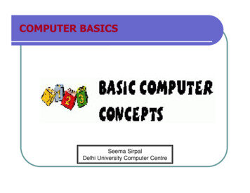
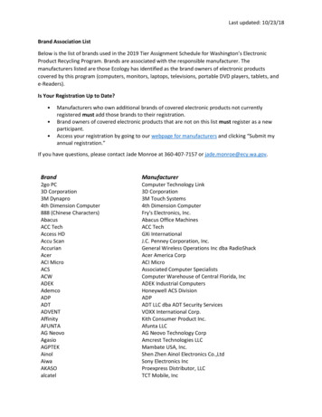
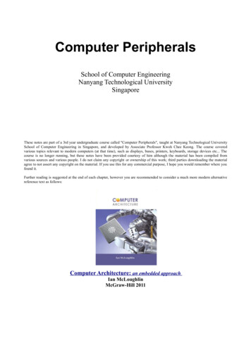
IntroductionISOJIS0.3.3International Standards Organization, safety, ergonomics, industrial standardsJapan Industrial Standards, safety, industrial standards.Computer I/O ArchitectureBefore proceeding with the study of computer peripherals, a brief review of thearchitecture of the computer, the requirements of interface design, and the structure of computerbuses will be given.[TC1]The digital computer normally consists of the central processing unit (CPU), memory,input devices, output devices, and storage devices as shown in Fig. 1.1. Interconnecting thesecomponents are the address, data and control buses. It is seen that each of the peripheral devicesis connected to CPU through the interface unit. These interface units generally comprise thefollowing:(i)Transmit and receive data registers/buffer: As the CPU and the peripheral operateasynchronously at different speeds, these registers and buffers (FIFO) are use to holdand transfer data to and from the peripheral device. The length of these registers isnormally the same as the data-word length of the peripheral device.(ii)Control registers: One or more control registers are used to capture and store thecommand received from the CPU. With programmable devices, mode registers are usedto set the mode of operation of the device.(iii)A status register: Each bit of the status register is used to indicate individual statusconditions to the CPU. Sometimes the CPU also writes the status register. In this casethe peripheral reads it to determine the status of the processor.(iv)An address decoder: Irrespective of whether the device is interfaced using memorymapped or I/O-port techniques, the device will still have to decode the addressinformation from the CPU to determine whether it should respond. Again forprogrammable devices, a series of addresses is decoded.CPUMemoryLocal vicesStorageDevicesBridgeOtherBus systemFigure 1.1 Local bus(v)Random logic: For simple devices, random logic circuits may be used to check thestatus registers, read and write the data registers, perform timing, handle interruptwww.lintech.org
Introduction4signals and other functions. However, an embedded micro controller chip is frequentlyused.0.4.Interfacing to Input/Output DevicesInterfacing between a CPU and a peripheral usually involves a trade-off between hardwareand software. The advantage of hardware is speed, whereas the disadvantages are cost andinflexibility. The advantage of software is versatility, whereas its main disadvantage is its slowspeed.Interfacing can be handled entirely by the CPU (in software, with minimal hardwaresupport), or at the other extreme, by a dedicated (intelligent) peripheral controller (in hardware,with minimal software support). Somewhere between these two extremes is the more usual master(CPU)-to-slave (peripheral) configuration, where the (dumb) peripheral support chip has anumber of built-in functions, accessible by the CPU writing various bit patterns to its onboardcontrol (command) register(s). The peripheral support chip handles many of the tasks with whichthe CPU would otherwise need to concern itself.Table 1.1 Typical peripheral support C6821 (8-bit)MC68230 PROGRAMMABLETIMERMC6840 (8 bit)MC68230 (16-bit)i8253,54Z8430Z8036CRT CONTROLLERMC6845 (8-bit)i8275KEYBOARDi8279BUSCONTROLLERi8286, 89, 289i82188, 288FLOPPY DISKCONTROLLERMC6843 (8-bit)i8271PRIORITY INTCONTROLLERMC6828i8259DMACONTROLLERMC6844 (8-bit)MC68440 (16-bit)i8237, 57MEMORYCONTROLLERMEMORYMANAGEMENTZ8410i8202, 3, 7, 8(DRAM)MC6829 (8-bit)MC68451 (16-bit)Z8010,15A recent trend has been the emergence of coprocessor peripheral support chips whichenable the CPU and coprocessor to carry out their respective tasks concurrently, communicatingwith each other upon completion. In many cases, these coprocessors are so intelligent that theirprocessing ability rivals that of the host CPU. The resulting configuration more closely resemblesa multiprocessor or distributed processing system, rather than the more traditional CPU-supportchip master-slave relationship. For example, the PCI support chips that your have learned inCE302.www.lintech.org
Introduction5Another trend has been the emergence of custom peripheral chips where, rather than use astandard off-the-shelf support chip, a designer programs a dedicated single-chip microcomputerto perform the desired task (for example, the i8041 used in the keyboard of the IBM PCKeyboard). The success in the marketplace of specific microprocessor chips depends not only onthe inherent qualities of the parent CPU, but also on the ready availability of both support chipsand software for the processor in question. Ready access to data sheets, application notes andtechnical supports (within the local geographical area) are further factors that sway a usertowards one particular processor over another.In terms of functionality, it could be argued that one specific peripheral chip is superior toanother; manufacturers can supply so-called benchmarks which purport to show the superiorityof their products over their competitors. Such benchmarks should be regarded with a certaindegree of healthy scepticism however, unless they originate from an 'independent' third party. Asa rough rule-of-thumb, designers should choose support chips from the same processor family asthe CPU itself; whether they be actually manufactured by the chip designer, or by a secondsource company manufacturing the chips under license. After all, such support chips aredesigned to work with that particular microprocessor (although this did not prevent Apple fromusing Intel, Zilog and Synertek chips to support the Motorola CPU in their Macintoshcomputer!).Generally speaking, 32-bit support chips from the same manufacturer are more powerfulthan 16-bit support chips, just as 16-bit chips are more powerful than 8-bit support chips.Comparing 8-, 16- or 32-bit support chips from different manufacturers is not thatstraightforward however; a lot depends on the particular application. Independent comparisonsusually show that such support chips are functionally equivalent at least. Table 1.1 provides arepresentative sample of the more commonly available microprocessor peripheral support chips.Nowadays, whenever a new microprocessor is released into the marketplace, it usuallyincorporates the ability to utilise the already (and often quite substantial) support chip andsoftware base from the previous processor generation. For example, in the case of the MC68000,Motorola designed into this processor the ability to interface to the already existing, tried andproven family of MC68000 support chips; although the MC68000 is basically an asynchronousprocessor, it also has the ability to interface to synchronous support chips. Newer (asynchronous)16/32-bit support chips were subsequently developed to interface specifically to theMC68000(20,30). A similar situation applies with the Intel family, which were able to utilise theearlier i8080(86) support chips.The Motorola MC68000 families use memory-mapped I/O and run on a synchronizingE(nable)-clock. Intel and Zilog support chips do not depend for their operation on a synchronizingclock signal from the CPU. They also assume ported I/O rather than memory mapping. In recentyears, support chips have been designed specifically to interface to the newer 16/32-bitprocessors released by Intel, Motorola, Zilog, National Semiconductor and others.Intel processors support ported I/O, whereas Motorola processors support memorymapped I/O. The advantage of memory mapping is that all I/O locations are addressed in exactlythe same manner as memory locations; no special repertoire of I/O instructions is thereforerequired (along with the various addressing modes for each). Thus the overall size of theinstruction set is reduced. A disadvantage with memory mapping is that some additional externaladdress decoding is necessary to discriminate between memory and I/O devices (this is donewithin the CPU for ported I/O schemes). Another disadvantage is that some of the availableaddress space is taken up with I/O device locations; not all of it is available for memory. Note,however, that with ported I/O systems, not all of the available I/O address space is always used.This means that memory-mapped I/O is more flexible.www.lintech.org
Introduction6It should be pointed out that memory mapping can be used with Intel processors, over andabove the inbuilt ported I/O structure, assuming that the additional external decoding circuitry isprovided.When interfacing between a CPU and a peripheral device, it is usual to provide some formof bi-directional buffering between the two. This is often in the form of onboard registers withina peripheral support chip. Having the data buffered within the I/O port means that the CPU can,in effect, be reading from (or writing to) the I/O port at the same time as it is performing someother function. This leads to rudimentary concurrent operation. Such buffering also allows fordifferent speeds between the CPU and peripheral device, for example, a printer will not be able tokeep pace with characters reaching it from a CPU: a block of characters (say 256 bytes) istherefore buffered within the I/O section (in dedicated local memory).Buffering is also often required between CPU and a peripheral device due to the differentelectrical characteristics of the two devices. The CPU usually operates at TTL logic levels ( 5V[HI] and 0V[LO]) whereas peripheral devices can have many different voltage and currentcharacteristics.Voltage level translation, scaling (up or down), current boosting (or limiting), or evenanalog-to-digital (and digital-to-analog) conversion might be required, depending on theperipheral in question.An I/O interface can also act as a translator, adapting signals from one format (say ASCIIor BCD) to another (binary).Software input and output buffers will often is required over and above the hardwarebuffers just discussed. Double buffering is commonly used, while circular buffering is needed forhighly asynchronous operation such as network communication protocol. Double bufferingallows the peripheral device to transfer a block of data into one area of memory while the CPU issimultaneously fetching data placed into another area of memory on a previous occasion. Eachbuffer is used alternately by the CPU and disk. At times, the disk will be transferring data intobuffer A, at the same time as the CPU is fetching data from buffer B. At other times, the diskwill be loading buffer B, and the CPU will be fetching data from buffer A. Double buffering thusallows for concurrent operation.In a circular buffer, the PC and the peripheral device are simultaneously filling andremoving items from the First-In-First-Out (FIFO) buffer. In practice, care must be taken toselect a buffer length sufficiently large so that buffer overflow does not occur (pointer movementsare restricted to modulo of buffer length). The circular list is empty whenever the PC and theperipheral device pointers become equal. A typical application of such a data structure is in aserial data communications link, where characters arrive at random intervals, but where the CPUremoves them at regular intervals. (The circular list thus acts as a buffer between theasynchronous peripheral device and the synchronous processor.)0.5.I/O Interfacing TechniquesThe times at which data reaches a computer from the outside world can be quiteunpredictable. The processor therefore needs some means of synchronising itself to externalevents, for scheduling I/O transfers. There are two main methods of achieving thissynchronisation, namely polling and interrupts.0.5.1.PollingPolling is a software technique whereby the processor continually asks a peripheral deviceif it needs servicing. During input, the I/O device sets a flag in the status register (SR) when itwww.lintech.org
Introduction7has data ready for transferring to the CPU. Subsequently when the device is polled, the processorreads this status and goes on to read the data in. Similarly when the CPU has data to output, itpolls the device to check for a ready status, upon which data is then written into the peripheraldevice. Several such I/O devices can be polled in succession, with the processor jumping todifferent I/O software routines, depending on which flags have been set.Polling works well if a minimum amount of processing is required in response to each setflag. For slow I/O transfers, the processor will be spending most of its time in its polling loop,asking each I/O device in turn if it has any data ready. This amount to wasted time, during whichthe CPU could be carrying out other useful tasks. In applications where there is little else for theprocessor to do (such as in keyboard scanning, for example), this is fine, but for applicationswhich involve substantial calculation as well, this amounts to inefficient use of the processor. Theadvantage of the polling technique is its simplicity.0.5.2.InterruptsRather than have the CPU continually asking I/O devices whether they have any dataavailable (and finding most of the time that they have not), a more efficient method is to have theI/O devices tell the processor when they have data ready. The processor can be carrying out itsnormal function, only responding to I/O transfers when there is data to respond to. On receipt ofan interrupt, the CPU suspends its current operation (storing the contents of its program counter,SR and other registers), identifies the interrupting device, then jumps (vectors) to the appropriateinterrupt service routine (interrupt handler).The advantages of interrupts, compared with polling, are the speed of response to externalevents and the reduced software overhead (of continually asking I/O devices whether they haveany data ready). Its main disadvantages are software commissioning and maintenance, and theadditional hardware overhead required (in the form of device identification, supplying vectorinformation and priority resolution).A typical interrupt interface requires two handshake controls. The two handshake controllines that interface between the CPU and I/O port are Interrupt Request and InterruptAcknowledge. Most systems will have more than one I/O port, with its associated set of interrupthandshake lines, so that some form of external (hardware) arbitration will be necessary in orderto resolve priorities. This priority resolver decides in which order the devices will be serviced inthe event of multiple interrupt requests occurring.With more than one possible interrupting device, a priority must be allocated to each.Within the CPU it will therefore be necessary to mask off lower priority interrupts, and torespond only to those of higher priority (non-maskable interrupts, however, must always beresponded to by the processor, a typical example being a system control console). In cases whereseveral devices are allocated the same priority level, additional external hardware (in the form ofa PIC) will be necessary.There will be some means within the CPU whereby interrupts can be enabled and disabled.For example, the very first function performed by the interrupt handler is to 'disable furtherinterrupts', so that the current interrupt can be attended to first. Any interrupts that occur duringthe servicing of this first one will usually be latched into the I/O port, and remain pending untilthe processor is ready to deal with them (that is, providing their priority level was higher than thecurrent mask).Some processors also provide an auto vector facility, whereby the starting location of theinterrupt service routine can be set automatically within the CPU, depending on its priority level.www.lintech.org
Introduction0.5.3.8Direct Memory Access (DMA)Interrupts provide fast response to a peripheral device, but the servicing of the interrupt isperformed in software. Sometimes I/O transfers need to occur faster than interrupts can manage,such as with disk I/O, high-speed graphics, or interfacing to a Local Area Network (LAN). Theservicing previously carried out by software can be performed faster if it is done by specialisedhardware. Such a dedicated controller is designed to perform one specific task only, namely thehigh-speed transfer of data between the I/O device and memory (and vice versa), but bypassingthe CPU. Hence the technique is referred to as Direct Memory Access (DMA).With DMA, the device actually takes control of the system bus for the time required totransfer the data, then hands back the bus to the CPU upon completion. Most harddiskcontroller uses a DMA Controller (DMAC) for data transfers between disk and memory. Thedisk is connected to a peripheral controller which communicates to the DMAC via the TransferRequest and Transmit Acknowledge handshake lines. The DMAC in turn interfaces to the CPUvia the Bus Request, Bus Acknowledge and Transfer Complete lines.It is important to realise that the DMAC itself is accessed by the CPU as a typical I/Odevice, with its own unique port ID, vector and interrupt priority. However, once the DMAChas been granted the bus in 'burst' mode, it cannot be interrupted by the CPU (in this sense theDMAC has priority over the processor). With 'interleaved' or 'cycle steal' DMA, the DMAC andCPU share alternate bus cycles.DMA transfers are inherently faster than either interrupts or polling, since they bypassaltogether the imbedded instruction fetch-decode-execute cycles of the CPU. Rather thanfetching instructions sequentially from memory, a DMAC has inbuilt (firmware) instructions.Moreover, these instructions can be executed concurrently, for example, transferring data at thesame time as decrementing a byte counter.0.6.SummaryIn this introductory chapter, we revised interfacing of Input/Output (I/O) devices to aCPU. In current development, this is usually facilitated by the use of user-programmableperipheral support chips. Such peripheral chips are connected to the CPU in master-slaveconfiguration, with their onboard command and status registers accessible via the system bus.More recent peripheral support chips comprise dedicated I/O processors, some of which employa coprocessor philosophy, which leads to concurrent operation of the peripheral chip and theCPU.Memory-mapped and ported I/O schemes were compared and contrasted, and theadvantages and disadvantages of each mentioned.The need for both hardware and software buffering between CPU and peripheral devicewas highlighted - the former for matching electrical signal levels, and the latter for thetemporary storage of data until the CPU (and/or peripheral) can deal with it.The basic I/O techniques of software polling, interrupts and Direct Memory Address(DMA) were introduced, and their respective advantages and disadvantages pointed out.0.7.Reading GuidesWILKINSON & HORROCKS, Sections 2.2, 2.4FULCHER, Sections 1.2, 1.5, 1.6, 3.4www.lintech.org
0.3. Computer I/O Architecture Before proceeding with the study of computer peripherals, a brief review of the architecture of the computer, the requirements of interface design, and the structure of computer buses will be given.[TC1] The digital computer normal