Transcription
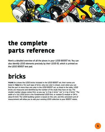
Black Box – A Porch PackageProtection SystemAdam Cuellar, Jacky Li, Louis Rondino, NathanChongrelevant information such as expected barcode(s), the timeit was unlocked, and more. There are three ways BlackBox will open: (1) authorized fingerprint used onfingerprint scanner; (2) matching barcodes from thepackage and the expected barcode; (3) unlocking featurein mobile app.II. SYSTEM COMPONENTSUniversity of Central Florida, Department ofComputer and Electrical Engineering, Orlando,Florida, 32816, U.S.A.Abstract — The main focus of this paper is to detail thedesign process of the Black Box and how it providescountermeasures to porch package theft. It contains uniquefunctions to how the user can unlock the box and provides acreative method for postal carriers to deliver valuable mail.Package security is provided by the locking mechanism andthe fingerprint scanner while the barcode scanner grantsfeasibility for mail carriers to access the box by scanning theauthorized barcode on the package. By having Wi-Ficapabilities, a dedicated server, and a mobile app, the usercan obtain useful information regarding ambienttemperature inside the protection system, the time and datethe box was accessed, and can manually open the boxthrough the app.Using these features all together, theBlack Box produces a practical approach to discourage mailtheft.Index Terms—Bar codes, consumer protection,fingerprint recognition, mobile applications, wirelesscommunicationI. INTRODUCTIONPurchasing valuables through online services is acommon practice in this day of age. However, millions ofAmericans experience porch package theft quite too oftensince in many cases, he/she was not present to receive it.To provide countermeasures to this crime, the Black Boxis created using innovative methods and technology.A main board using the ATMega2560 microchip isdesigned and created to integrate peripherals it must have.These peripherals include: the fingerprint sensor, barcodescanner, Wi-Fi system on chip, locking mechanism, andpower supply. These components are carefully placedinside a 22 x 19.5 x 17 in. sturdy, lightweight box. Theinitial state of the Black Box is in standby mode, in whichit waits for an instruction by the user (to unlock it) or bythe postal carrier by which he/she will use the barcodescanner to scan the authorized barcode on the package.The ESP8266 Wi-Fi system on chip allows wirelesscommunication with a dedicated server that containsThis section briefly describes the individualcomponents or modules that were either designed orbought to integrate. Each component is necessary forrealizing the capabilities and functions of Black Box.A. MicrocontrollerThe most crucial component to any embedded system isthe microcontroller. Thus, the ATMega2560 is mainlychosen because of the flexibility it provided for choosingmodules to interface it with. It comes with 4 UART, 5SPI, and 1 I2C digital communication peripherals.Having these many options allows for any design team tocomfortably choose other modules to integrate with.Additionally, the ATMega2560 contains a sufficientamount of flash memory and nonvolatile memory pairedwith a clock speed of 16 MHz. This speed is necessarybecause it is desirable for the MCU to verify barcodematching when postal carriers deliver parcels.B. Locking MechanismA locking mechanism is needed to keep packages safeand secured when postal carriers make their deliveries toBlack Box. Researching and using a locking mechanismthat is easy to integrate into the overall system is an idealcharacteristic. Thus, the Atoplee electric door lock, asshown in Fig. 1 is chosen due to its simple yet effectivedesign. It operates at 12 volts DC at a current of 2 amps,according to the product details. Additionally, the lockcontains two sets of red and black wires which signify thepower line connections while the other pair signifies thelimit switch.C. Barcode ScannerThe barcode scanner is a module that postal carrierswill be interacting with the majority of the time with thesystem. Thus, a reliable barcode scanner module is neededwhich is why the Waveshare barcode scanner is chosen. Itoperates at a voltage of 5 volts with an operating currentof 135 mA. Furthermore, with a dimension size of 53.3 x21.4 mm, this module can easily be placed at convenientareas of the Black Box.
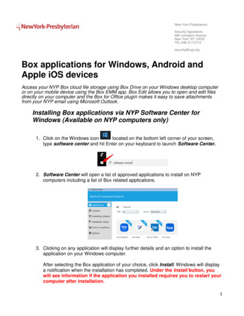
speed of 80 MHz, the ESP8266 can perform calculationsto verify barcode matches and to retrieve and transmitrelevant data to the server.F. Temperature SensorA temperature sensor is needed for Black Box to let theuser know the temperature inside it. This helps the userkeep in mind of temperature sensitive mail. The STS30DIS is a valid option as it measures an acceptable range oftemperature from 32 – 149 degrees Fahrenheit. Averagetemperatures nationwide ranges from a low 26.6 ºF to ahigh of 70.7 ºF in which this sensor can detect. It operatesat a voltage range of 2.15 – 5 volts drawing about 600 –1500 microamps. Additionally, it uses I2C communicationwith a communication speed of 1 MHz. With this speed,the sensor can keep an updated heat measurement to theuser.Fig. 1 Atoplee DC solenoid locking mechanismuses a latch and has an emergency lever to triggerthe lockD. Fingerprint SensorThe fingerprint sensor will be used to keep Black Boxsecured by granting access only to the user’s fingerprints.Thus, the Flash Tree fingerprint scanner is chosen tofulfill this role. By simply scanning the user’s uniquefingerprint, entry to Black Box will be gained. A highpowered DSP chip does the image rendering, calculation,feature-finding and searching. It can connect to anymicrocontroller using TTL (transistor to transistor logic)interface. The user stores fingerprints by using a Windowssoftware and provides great synergy with Arduino boardssuch as the ATMega2560. This is because a library existsin the Arduino IDE. It operates at a voltage range of 3.6 6 volts, an operating current ranging from 120 - 150 mAand can store 162 fingerprints which is stored in its’ flashmemory of 256 bytes.E. Wi-Fi SoCThe ESP8266 is a Wi-Fi system on chip that grants WiFi connectivity to MCUs that lack this ability. This chipca be used to host an application or offload Wi-Finetworking functions from other applications processors.It provides great synergy with the ATMega2560 since alibrary exists within the Arduino IDE. Additionally, it cancommunicate using SPI, UART, I2C, and I2S serialinterfaces, providing much needed flexibility.Theoperating voltage and current are 2.5 to 3.6 volts and 20microamps to 170 milliamps, respectively. With a clockG. Equipment EnclosureAn enclosure is needed not only to house all theequipment, but also, to be able to hold most packages thatcome in different sizes. To do this, about 70% ofdifferent sized boxes from Amazon needed to fit inside abox large enough to accommodate. The enclosuremeasures 22 x 19.5 x 17in which is enough. In practicalpurposes, the enclosure will have to be drilled into theground to prevent thieves from picking up the box itself.III. SYSTEM CONCEPTThis section describes how the Black Box works as acomplete system. Based on Fig. 2 the Black Box behavioris cyclical and this process can be summarized in foursteps: lock, verify, unlock, repeat.During the initial state of Black Box, it is assumed thatthe system has already established Wi-Fi connectivity viathe ESP8266EX module with the user’s router. WhenBlack Box is closed and locked, the system is in standbymode. At this time, if the postal carrier is delivering apackage, he/she would have to scan the barcode of thepackage. A button is placed near the barcode scanner toturn it on to begin scanning. If the barcode is correct, themain board will send a signal to the locking mechanism tounlock. If it is incorrect, the system will not open. Oncethe delivery person carefully closes Black Box, arecording of this event will take place. The softwarerunning in Black Box will notify the dedicated server thetime that it was accessed along with other informationsuch as current temperature. For a more detailed
explanation on the software, Section IV Software inDetail, gives more technical details.registered fingerprint on the scanner, the verificationprocess begins, which leads to the main board to send asignal to unlock the locking mechanism. It is important tonote that the user must register his/her fingerprint prior touse. The other method is to use the mobile applicationwhich communicates with the server and the Black Box.The mobile application allows the user to press a buttonlabeled “Unlock Box” which triggers the lockingmechanism. Further details are mentioned in Section VSoftware in Detail under the mobile application subcategory. After the user has opened Black Box to retrievethe ordered valuables, the cycle restarts back to it beingclosed and locked, waiting for a new package to bedelivered.IV. HARDWARE IN DETAILThis section will further describe the modules brieflydiscussed in Section II System Components without thedescription of the microcontroller, since each technicaldescription will incorporate how the modules connect andcommunicate with the MCU. Each module explanationwill incorporate how they are connected with the MCUand they function with it.A. Locking MechanismFig. 2 Transitional Flow of each blockThe user is given two choices to unlock the Black Box.One way is through the fingerprint scanner. By placing aAs shown in the lock contains two sets of red and blackwires with one set signifying the power line connectionswhile the other set of lines are for the limit switch. Thelimit switch lines are important to the MCU as it tells theMCU when the locking mechanism is opened or closed. Itis normally closed (locked) which means that the switch ison; thus, a signal is transmitted to the MCU. When it isopened, the switch is off, and the transmission signal is nolonger being carried to the MCU. This way, if there is anissue with locking, for example if the mail carrier does notfully close the box, the user can be alerted that the lock isnot set.Even though the product details described the lockhaving an operating voltage of 12 volts with an operatingcurrent of 2 amps, multiple tests were made to test theaccuracy of those results. When the voltage is at no load,it is measured with a value of 11.96 volts. With the loadof the latch, the voltage dropped to approximately 9 volts.By taking the average of the voltage drop under loads, itwas concluded that a voltage of 10.36 volts is needed toallow the locking mechanism to trigger. Additionally,these tests provided data for how much current is drawnunder load which resulted to a current of 1.02 amps.One last characteristic that needed to be tested beforethis lock was implemented to the system is the potential
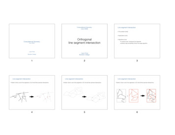
negative current that will be sent back through the device.A common problem with solenoid mechanisms with aninductive load is that when circuit switches open, thecollapse of the magnetic field causes a negative current.To test this problem, the voltage is measured whenswitching the lock on. In, this test is demonstrated andmeasured. This is seen in Fig. 3.This test concluded that a fly back diode is necessary, asalmost -1 volt is produced when switching off thesolenoid. Given that the measured internal resistance ofthe solenoid is 5.9Ω, this translates to 170mA ofreverse current.the MCU was able to read the status of the lock from itsinternal limit switchFig. 4 Lock Response to Microcontroller ResponseFig. 3 Voltage Waveform reverse currentFor breadboard testing, the MOSFET used is theIRF630B. Thankfully, with a drain current of 9A anddrain-to-source voltage of 200V max, this MOSFET hasenough voltage and current capacity to drive the lock forthese tests. Since the gate-to-source voltage is high,however, an input resistor for this test is not used. This isdone to maximize the signal current from the GPIO of themicrocontroller. Due to the low frequency on time of lessthan one quarter of a second, this resistor should not beneeded to protect the microcontroller. To dissipatecapacitance and act as a pull-down resistor, a 10kΩresistor is attached between the source, which is grounded,and drain of the MOSFET. As a result of the previoustests and measurement of the reverse current, a standard1N4148 diode is used with the cathode at 12V across theinductive load that is the lock.The resulting waveforms shown in Fig. 4, concludesthat the design for the lock switching mechanism workswith the ATMega2560. Set to pulse the lock for 100ms,less than the half second maximum specified by themanufacturer, the lock accurately executed an unlock andSince the feedback from the lock is a simple limitswitch, the input can be pulled to a GPIO pin on theATMega2560 high through a 10kΩ resistor and let thelimit switch pull it low when actuated. Since the lock is aninductive solenoid requiring 12V, a MOSFET is needed toactuate it. The chosen MOSFET is capable of “logiclevel” actuation with a VGS of 4V at RDS (on) of 100mΩ.The 4V is well above the 3V logic high level specified inthe 5V logic standard but still below 5V enough that acurrent limiting input resistor of 220Ω can be utilized. Anadditional 10kΩ resistor is added between the gate andsource of the MOSFET to help dissipate capacitance.The IRLL024NTRPBF also contains an internal zenerdiode to help against reverse current from its selfinductance. Since the battery voltage is plenty for thelocking mechanism, simply supplying the lock with 12Vthrough the header straight from the battery and backthrough the N-channel MOSFET on the low side isenough. From the prototyping tests, it was discovered thatthe DC solenoid inductive lock does return reverse currentwhen the MOSFET is opened. To mitigate this, a flybackdiode is added to prevent the current from reaching theMOSFET or worse the MCU. Similar in characteristics toa 1N4148 diode used in prototyping, theMMBD914LT1G has a forward current of 200mA andforward voltage of 1V. This is plenty to mitigate the lowreverse current supplied by the breakdown of thesolenoid’s magnetic field. Thus, this circuit allowsactuating the locking mechanism of the system safely,easily, and fast.
B. Barcode ScannerThe Waveshare Barcode Scanner Module is capable ofdecoding one-dimensional and two-dimensional barcodeson paper or screen with great accuracy. It is versatile inthe sense that in can be plugged through its onboard USBand UART interface. Additionally, due to its smalldimension of 53.3mm 21.4 mm, the device can be easilyintegrated into types of devices. A white light is used witha light intensity of 250 lux and can scan a typical serialbarcode such as a Code 39 at a maximum distance of 25.0centimeters. In general, the minimum distance required forscanning is about 6 centimeters. Since UART serialcommunication will be used with the MCU, the defaultparameters of the interface are at a baud rate of 9600 bps,data bit: 8, and a stop bit: 1.C. Fingerprint SensorThe Flashtree fingerprint sensor makes fingerprintdetection and verification simple. Two requirements arenecessary for putting the module into use.(1) The user must enroll his/her fingerprint – this is doneby assigning ID numbers to each print which will beused for query later(2) The user can search for fingerprints – searchinginvolves asking the sensor to identify which ID isphotographed.To enroll fingerprints, the user must use their softwarethat is only available to Windows. The user manualcontains a code used for programming the fingerprintsensor to begin scanning and assigning IDs to fingerprints.This sensor uses simple communication with MCUs byusing GND, RX, TX, and VCC wires.successfully. On the receiving end, or going from the 5VMCU to the 3.3V ESP8266, this higher voltage canpossibly damage the Wi-Fi module. To remedy this,simply use a voltage divider to step down the 5V from theMCU to a safe 3.3V for the ESP8266.(1)When testing in the lab, resistor values of 1.8kΩ and3.2kΩ were used to generate a 3.2V signal into theESP8266. The 3.2V as opposed to 3.3V allowed a goodmargin of error to not risk damaging the ESP8266 bygoing above 3.4V. Furthermore, since the logic level is3.3V, a 2V signal is considered high by this device.Testing this voltage divider system as a logic levelconverter helped understand the different communicationrequirements used in modern systems. In Fig. 5, it showshow the connection for our wireless module is configured.Using the standard size 2.54 female two by four headeropposite of the male Wi-Fi module header, the ESP8266can be plug and play once the PCB was printed. The ideaof this is if the Wi-Fi module has a possibility of beingfaulty, it can easily be replaced by just pulling it off andplugging back a new Wi-Fi module back to the 2x4header. Additionally, having the antennas for our Wi-Fion a completely separate board helped avoid unwantedsignal loss or noise due to the inductive nature of thelocking mechanism and MOSFET.D. Wi-Fi SoCThe major issue of integrating the ESP8266 is seenwhen considering that the microcontroller runs at a 5Vlogic level and the ESP8266 runs at 3.3V. Though theESP8266 may work most of the time when 5V is input toit, the datasheet does not specify that it is a 5V tolerantdevice. Therefore, in order to safely communicate usingUART between these two devices, the logic level must beconverted. There are integrated circuits available that cando this for use; however, since regulated voltages are whatare being worked with, there must be a simpler way toconvert these signals. When sending data from theESP8266 to our MCU, the 3.3V signal is lower than 5Vand safe for the device. It is also above the 3V logic highthreshold for 5V logic and will correctly register a highversus low logic signal. Since these voltages are regulated,it is safe to say that the 3.3V signal triggers a high signalFig. 5 Wi-Fi Module HeaderE. Temperature SensorThe STS-30-DIS is a board mount temperature sensordesigned by SENSIRON. Its functionality includesenhanced signal processing, two distinguished andselectable I2C addresses, and a communication speed of 1
MHz max. To see how this sensor is integrated with theMCU, Fig. 6 is shown.Fig. 6 Temperature Sensor HeaderPin 1 is connected along with a 10k pull up resistor forthe SDA pin which is the serial data pin where it send andreceive data. Pin 2 is connected to ADDR which canspecify a different address depending on whether it ispulled high or low. Arbitrarily, it is pulled low for theaddress 0x4A. Pins 3 and 6 can be left untouched sincethey are used if the STS-30-DIS is preprogrammed for analert threshold. Pin 4 is connected to SCL along with a10k pull up resistor as required on the data sheet provided.Pin 8 is dedicated to ground. Pin 7 is R which is has nofunction but needs to be connected to our VSS or GND.Pin 5 is connected to a constant 5V source which is ourVCC pin. Lastly EXP pin is consider the die pad so thispin is also connected to the ground or floating. It doesn’tmatter but it is recommended that it be soldered to the padfor mechanical reasons. C13 is required to reduce noisegoing into the chip power, which could adversely affectthe readings received.F. User and System FeedbackFig. 7 User and System FeedbackBlack box relies on sensors and visual feedback fromand to the user to accomplish its goals. This is facilitatedby two different switches which can detect if the box isopened or closed and if the lock is locked or unlocked.For this part of the schematic shown in Fig. 7, thecomponents included are the inputs for a reed switch todetect the state of the lid of the box, a button input todetect when a user is trying to scan a package, and anLED to display to the user when the box is unlocked.The LED and button are simple components which aremounted to the top or front of the box and connected tothe main board through cables. Since they both are locatedin the same relative area of the box and both require aground connection, they share the same header on themain board. The LED utilizes pin 1 on the header, whichconnects through a 1kΩ current limiting resistor to ageneral-purpose input and output register on themicrocontroller. The button, however, connects directly toanother GPIO pin on the board while being pullednormally high to VCC through a 10kΩ resistor. The reedswitch works in the same manner as the user input button;however, it is actuated by a magnetic field triggered by amagnet on the lid of the lock. In the same manner as thebutton, it is pulled high with a 10kΩ resistor. This allowsthe user to both know when the box is closed and when itis locked to avoid unrecommended states such as the boxbeing open, and the lock locked, or the box being closedand the lock unlocked.V. SOFTWARE DETAILThis section will describe in depth how the softwareinteracts with each module. Additionally, the server andthe mobile application will be discussed.A. Embedded SoftwareTo program the main board, C language is used in theArduino IDE as well as the process of bootloading.Before the bootloading process was initiated, a 16MHzcrystal and two 22pF capacitors are needed to make afunctional clock for the microprocessor.Thesecomponents are placed in their respective pin destinationsbased on the datasheet of the ATMega2560.Boot loading involves using an in-system programmerto install firmware into a blank chip. This is demonstratedas an example in Fig. 8.
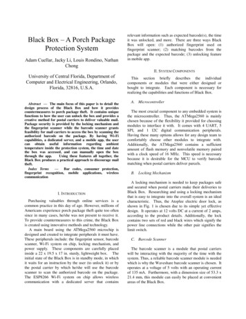
Fig. 8 Arduino Uno used as an ISP to bootload firmwareto target boardThe target board has no functions until the bootloaderon the programmer board loads in bootloader. Manydevelopment boards have an all-in system programmingheader within the development board. For Atmel, theyintroduce a circuit seral programming header for manyself-made projects, helping users jumpstart with a breeze.To read or write over UART, it is necessary to set upserial communication parameters to match exactly withthe other modules used in the system. Shown below is theexact configuration used within Tera Term. Baud Rate: 9600Data: 8 bitParity: NoneStop Bits: 1 bitFlow Control: noneThis allowed for the most effective communicationbetween the ATMega2560 MCU and the componentspurchased that involve serial communication.B. iOS Application and Server TestingTesting the iOS Application and web server come handin hand due to the nature of the application relying solelyon the web server. The iOS application is tested using theXCode IDE. The web server is tested using AdvancedRest Client to ensure that the HTTP requests areimplemented as intended. Both the MCU and theapplication are used to communicate to the web server toensure the efficiency of the handling of data.To ensure that communication is established with theESP8266, ATMega2560, and the sample serve, a sampleiOS application that allows HTTP requests to be sent overthe iOS device is created. The application sends HTTPrequests just as Advanced Rest Client would do and cansend/receive JSON packages. If a JSON packet isreceived, then it is properly decoded and processed by theapplication. If a JSON packet needs to be sent, then thenecessary information is encoded accordingly. Using theapp, it was obvious to notice that the ESP8266 wascommunicating with the ATMega2560. The app was ableto tell the board to set the built in LED to high or lowdepending on the user’s preference.Using the information gathered by this testing, it isensured that the information received from system’smodules can be implemented to what the iOS applicationis capable of. Ideally, the application will be able to sendand receive these HTTP requests to interact with theBlack Box using the web server as a medium. It will alsobe able to display all the necessary information being sentfrom the Black Box to the server. Thus, these ideas wereimplemented to the mobile application and is completed.Implementation of secure software for the Black Box isimperative to its design. Secure code is written to preventusers, and malicious third parties, from gaining access tosoftware or information they should not normally haveaccess to. In this instance, data such as tracking temperatures, are kept secure and only accessible by theuser.The sensitive data tied to the Black Box are saved onthe server; therefore, malicious attacks such as SQLinjections can be detrimental to the user’s information. ASQL injection is when a malicious user intentionally craftsan input that is known to be used in an SQL query. Toprevent SQL injections the software implements sanitizingdata which causes any freeform user inputted data to beinterpreted as plain text.The configuration of the SQL database is alsoperformed very carefully. Many database managementengines contain an admin account which, if not properlyconfigured at set up, can become a major liability and leadto disastrous data leakages or corruption. In order toprevent this, our database system is secured with access toediting data from only one account with protectedcredentials.In Fig. 9, the completed mobile application is shown.Starting from left to right:(1) Login Screen – the user inputs his/her usernameand password to login.
Fig. 9 Mobile Application Transition Flow(2) Current Status & History – various information isgiven to the user. At the top of the screen shows thecurrent locking status of Black Box, thetemperature inside it in ºC, and the current date andtime.The history section displays previousoccurrences of when the box was accessed,(3) Settings – By pressing the top right arrow in theprevious state, the user can access the settings.This section allows the user to input the expectedtracking number/barcode. At this point, the usercan decide to go back to the previously mentionedstate or can proceed to the next feature.(4) Open Box – this allows the user to open Black Boxusing the mobile application. By pressing thisfeature, the current status and history will updateVI. CONCLUSIONWith the motivation to design a device that willdiscourage and prevent thieves from stealing preciouspackages, the Black Box project idea was created anddesigned. Throughout the two semesters, the four of us inthis group have met continuously, engaging in work andideas that would eventually come together to form theideal design. Overall, our group believes that we haveprovided enough research, plans, and testing to ensure anaccurate representation of the Black Box project idea.From the all the research and preparation that was done,our team was able to complete the necessary requirementsto complete the production of the box. There were manyobstacles and challenges that approached us; however, ifsenior design has taught us anything, it has taught us towork together as a group to accomplish what is needed tobe done which gives us a glimpse of how it will be like inthe real world when working as engineers.ACKNOWLEDGEMENTThe authors wish to acknowledge the assistance andsupport of Dr. Samuel Richie, Mikael Wasfy, and SeanSzumlanski. They are recognized for their superiorteaching methods and passion for teaching and guidingstudents to understanding difficult concepts in theirrespective fields.REFERENCES[1] Neamen, Donald A. Electronic Circuit Analysis andDesign. McGraw-Hill, 2006.InstrumentsCC3220SimpleLink Microcontrollers (MCUs).” Mouser Electronics /Texas-Instruments/ti-cc3220MCU/?gclid 6hbnsQNQuwLedN2bjUz3g8UJlmchoCbD4QAvD BwE.[3] “BU-203: Nickel-Based Batteries.” Nickel-BasedBatteries Information – Battery kel based batteries[4] https://www.arduino.cc/en/tutorial/arduinoISP[2] “Texas
ground to prevent thieves from picking up the box itself. III. SYSTEM CONCEPT This section describes how the Black Box works as a complete system. Based on Fig. 2 the Black Box behavior is cyclical and this process can be summarized in four steps: lock, verify, unlock, repeat.