Transcription
Steel StructuresDesign Manual To AS 4100First EditionBrian KirkeSenior Lecturer in Civil EngineeringGriffith UniversityIyad Hassan Al-JamelManaging DirectorADG Engineers Jordan
Copyright Brian Kirke and Iyad Hassan Al-JamelThis book is copyright. Apart from any fair dealing for the purposes of privatestudy, research, criticism or review as permitted under the Copyright Act, no partmay be reproduced, stored in a retrieval system, or transmitted, in any form or byany means electronic, mechanical, photocopying, recording or otherwise withoutprior permission to the authors.
CONTENTS123PREFACENOTATIONviiixINTRODUCTION: THE STRUCTURAL DESIGN PROCESS11.1 Problem Formulation1.2 Conceptual Design1.3 Choice of Materials1.4 Estimation of Loads1.5 Structural Analysis1.6 Member Sizing, Connections and Documentation113455STEEL PROPERTIES62.1 Introduction2.2 Strength, Stiffness and Density2.3 Ductility2.3.1 Metallurgy and Transition Temperature2.3.2 Stress Effects2.3.3 Case Study: King’s St Bridge, Melbourne2.4 Consistency2.5 Corrosion2.6 Fatigue Strength2.7 Fire Resistance2.8 References666778910111213LOAD ESTIMATION143.1 Introduction3.2 Estimating Dead Load (G)3.2.1 Example: Concrete Slab on Columns3.2.2 Concrete Slab on Steel Beams and Columns3.2.3 Walls3.2.4 Light Steel Construction3.2.5 Roof Construction3.2.6 Floor Construction3.2.7 Sample Calculation of Dead Load for a Steel Roof3.2.7.1 Dead Load on Purlins3.2.7.2 Dead Load on Rafters3.2.8 Dead Load due to a Timber Floor3.2.9 Worked Examples on Dead Load Estimation3.3 Estimating Live Load (Q)3.3.1 Live Load Q on a Roof3.3.2 Live Load Q on a Floor3.3.3 Other Live Loads3.3.4 Worked Examples of Live Load Estimation141414161717181819202122222424242425iii
iv4Contents3.4 Wind Load Estimation3.4.1 Factors Influencing Wind Loads3.4.2 Design Wind Speeds3.4.3 Site Wind Speed Vsit,E3.4.3.1 Regional Wind Speed VR3.4.3.2 Wind Direction Multiplier Md3.4.3.3 Terrain and Height Multiplier Mz,cat3.4.3.4 Other Multipliers3.4.4 Aerodynamic Shape Factor Cfig and Dynamic Response Factor Cdyn3.4.5 Calculating External Pressures3.4.6 Calculating Internal Pressures3.4.7 Frictional Drag3.4.8 Net Pressures3.4.9 Exposed Structural Members3.4.10 Worked Examples on Wind Load Estimation3.5 Snow Loads3.5.1 Example on Snow Load Estimation3.6 Dynamic Loads and Resonance3.6.1 Live Loads due to Vehicles in Car Parks3.6.2 Crane, Hoist and Lift Loads3.6.3 Unbalanced Rotating Machinery3.6.4 Vortex Shedding3.6.5 Worked Examples on Dynamic Loading3.6.5.1 Acceleration Loads3.6.5.2 Crane Loads3.6.5.3 Unbalanced Machines3.6.5.4 Vortex Shedding3.7 Earthquake Loads3.7.1 Basic Concepts3.7.2 Design Procedure3.7.3 Worked Examples on Earthquake Load Estimation3.7.3.1 Earthquake Loading on a Tank Stand3.7.3.1 Earthquake Loading on a Multi-Storey Building3.8 Load Combinations3.8.1 Application3.8.2 Strength Design Load Combinations3.8.3 Serviceability Design Load Combinations3.9 485051515153545454555656565757575859METHODS OF STRUCTURAL ANALYSIS604.1 Introduction4.2 Methods of Determining Action Effects4.3 Forms of Construction Assumed for Structural Analysis4.4 Assumption for Analysis4.5 Elastic Analysis4.5.2 Moment Amplification4.5.3 Moment Distribution4.5.4 Frame Analysis Software6060616165677070
Contents567v4.5.5 Finite Element Analysis4.6 Plastic Method of Structural Analysis4.7 Member Buckling Analysis4.8 Frame Buckling Analysis4.9 References7171737779DESIGN of TENSION MEMBERS805.1 Introduction5.2 Design of Tension Members to AS 41005.3 Worked Examples5.3.1 Truss Member in Tension5.3.2 Checking a Compound Tension Member with Staggered Holes5.3.3 Checking a Threaded Rod with Turnbuckles5.3.4 Designing a Single Angle Bracing5.3.5 Designing a Steel Wire Rope Tie5.4 References808182828284848585DESIGN OF COMPRESSION MEMBERS866.1 Introduction6.2 Effective Lengths of Compression Members6.3 Design of Compression Members to AS 41006.4 Worked Examples6.4.1 Slender Bracing6.4.2 Bracing Strut6.4.3 Sizing an Intermediate Column in a Multi-Storey Building6.4.4 Checking a Tee Section6.4.5 Checking Two Angles Connected at Intervals6.4.6 Checking Two Angles Connected Back to Back6.4.7 Laced Compression Member6.5 References86919698989999101102103104106DESIGN OF FLEXURAL MEMBERS1077.1 Introduction7.1.1 Beam Terminology7.1.2 Compact, Non-Compact, and Slender-Element Sections7.1.3 Lateral Torsional Buckling7.2 Design of Flexural Members to AS 41007.2.1 Design for Bending Moment7.2.1.1 Lateral Buckling Behaviour of Unbraced Beams7.2.1.2 Critical Flange107107107108109109109110
vi89Contents7.2.1.3 Restraints at a Cross Section7.2.1.3.1 Fully Restrained Cross-Section7.2.1.3.1 Partially Restrained Cross-Section7.2.1.3.1 Laterally Restrained Cross-Section7.2.1.4 Segments, Sub-Segments and Effective length7.2.1.5 Member Moment Capacity of a Segment7.2.1.6 Lateral Torsional Buckling Design Methodology7.2.2 Design for Shear Force7.3 Worked Examples7.3.1 Moment Capacity of Steel Beam Supporting Concrete Slab7.3.2 Moment Capacity of Simply Supported Rafter Under Uplift Load7.3.3 Moment Capacity of Simply Supported Rafter Under Downward Load7.3.4 Checking a Rigidly Connected Rafter Under Uplift7.3.5 Designing a Rigidly Connected Rafter Under Uplift7.3.6 Checking a Simply Supported Beam with Overhang7.3.7 Checking a Tapered Web Beam7.3.8 Bending in a Non-Principal Plane7.3.9 Checking a flange stepped beam7.3.10 Checking a tee section7.3.11 Steel beam complete design check7.3.12 Checking an I-section with unequal flanges7.4 23124126127128129131136140MEMBERS SUBJECT TO COMBINED ACTIONS1418.1 Introduction8.2 Plastic Analysis and Plastic Design8.3 Worked Examples8.3.1 Biaxial Bending Section Capacity8.3.2 Biaxial Bending Member Capacity8.3.3 Biaxial Bending and Axial Tension8.3.4 Checking the In-Plane Member Capacity of a Beam Column8.3.5 Checking the In-Plane Member Capacity (Plastic Analysis)8.3.6 Checking the Out-of-Plane Member Capacity of a Beam Column8.3.8 Checking a Web Tapered Beam Column8.3.9 Eccentrically Loaded Single Angle in a Truss8.4 ECTIONS1669.1 Introduction9.2 Design of Bolts9.2.1 Bolts and Bolting Categories9.2.2 Bolt Strength Limit States9.2.2.1 Bolt in Shear9.2.2.2 Bolt in Tension9.2.2.3 Bolt Subject to Combined Shear and Tension9.2.2.4 Ply in Bearing9.2.3 Bolt Serviceability Limit State for Friction Type Connections166166169167167168168169169
Contentsvii9.2.4 Design Details for Bolts and Pins9.3 Design of Welds9.3.1 Scope9.3.1.1 Weld Types9.3.1.2 Weld Quality9.3.2 Complete and Incomplete Penetration Butt Weld9.3.3 Fillet Welds9.3.3.1 Size of a Fillet Weld9.3.3.2 Capacity of a Fillet Weld9.4 Worked Examples9.4.1 Flexible Connections9.4.1.1 Double Angle Cleat Connection9.4.1.2 Angle Seat Connection9.4.1.3 Web Side Plate Connection9.4.1.4 Stiff Seat Connection9.4.1.5 Column Pinned Base Plate9.4.2 Rigid Connections9.4.2.1 Fixed Base Plate9.4.2.2 Welded Moment Connection9.4.2.3 Bolted Moment Connection9.4.2.4 Bolted Splice 811851871891891992062099.4.2.5 Bolted End Plate Connection (Standard Knee Joint)9.4.2.6 Bolted End Plate Connection (Non-Standard Knee Joint)9.5 References213226229
PREFACEThis book introduces the design of steel structures in accordance with AS 4100, the AustralianStandard, in a format suitable for beginners. It also contains guidance and worked exampleson some more advanced design problems for which we have been unable to find simple andadequate coverage in existing works to AS 4100.The book is based on materials developed over many years of teaching undergraduateengineering students, plus some postgraduate work. It follows a logical design sequence fromproblem formulation through conceptual design, load estimation, structural analysis tomember sizing (tension, compression and flexural members and members subjected tocombined actions) and the design of bolted and welded connections. Each topic is introducedat a beginner’s level suitable for undergraduates and progresses to more advanced topics. Wehope that it will prove useful as a textbook in universities, as a self-instruction manual forbeginners and as a reference for practitioners.No attempt has been made to cover every topic of steel design in depth, as a range of excellentreference materials is already available, notably through ASI, the Australian Steel Institute(formerly AISC). The reader is referred to these materials where appropriate in the text.However, we treat some important aspects of steel design, which are either:(i)not treated in any books we know of using Australian standards, or(ii)treated in a way which we have found difficult to follow, or(iii)lacking in straightforward, realistic worked examples to guide the student orinexperienced practitioner.For convenient reference the main chapters follow the same sequence as AS 4100 except thatthe design of tension members is introduced before compression members, followed byflexural members, i.e. they are treated in order of increasing complexity. Chapter 3 coversload estimation according to current codes including dead loads, live loads, wind actions,snow and earthquake loads, with worked examples on dynamic loading due to vortexshedding, crane loads and earthquake loading on a lattice tank stand. Chapter 4 gives someexamples and diagrams to illustrate and clarify Chapter 4 of AS 4100. Chapter 5 treats thedesign of tension members including wire ropes, round bars and compound tension members.Chapter 6 deals with compression members including the use of frame buckling analysis todetermine the compression member effective length in cases where AS 4100 fails to give asafe design. Chapter 7 treats flexural members, including a simple explanation of criteria forclassifying cross sections as fully, partially or laterally restrained, and an example of an Ibeam with unequal flanges which shows that the approach of AS 4100 does not always give asafe design. Chapter 8 deals with combined actions including examples of (i) in-planemember capacity using plastic analysis, and (ii) a beam-column with a tapered web. InChapter 9, we discuss various existing models for the design of connections and presentexamples of some connections not covered in the AISC connection manual. We give step-bystep procedures for connection design, including options for different design cases. Equationsare derived where we consider that these will clarify the design rationale.A basic knowledge of engineering statics and solid mechanics, normally covered in the firsttwo years of an Australian 4-year B.Eng program, is assumed. Structural analysis is treatedonly briefly at a conceptual level without a lot of mathematical analysis, rather than using thetraditional analytical techniques such as double integration, moment area and momentdistribution. In our experience, many students get lost in the mathematics with these methodsand they are unlikely to use them in practice, where the use of frame analysis softwareviii
Prefaceixpackages has replaced manual methods. A conceptual grasp of the behaviour of structuresunder load is necessary to be able to use such packages intelligently, but knowledge ofmanual analysis methods is not.To minimise design time, Excel spreadsheets are provided for the selection of member sizesfor compression members, flexural members and members subject to combined actions.The authors would like to acknowledge the contributions of the School of Engineering atGriffith University, which provided financial support, Mr Jim Durack of the University ofSouthern Queensland, whose distance education study guide for Structural Design stronglyinfluenced the early development of this book, Rimco Building Systems P/L of Arundel,Queensland, who have always made us and our students welcome, Mr Rahul Pandiya aformer postgraduate student who prepared many of the figures in AutoCAD, and theAustralian Steel Institute.Finally, the authors would like to thank their wives and families for their continued supportduring the preparation of this book.Brian KirkeIyad Al-JamelJune 2004ix
NOTATIONThe following notation is used in this book. In the cases where there is more than onemeaning to a symbol, the correct one will be evident from the context in which it is used.Ag gross area of a cross-sectionAn net area of a cross-sectionAo plain shank area of a boltAs tensile stress area of a bolt; orarea of a stiffener or stiffeners in contact with a flangeAw gross sectional area of a webae minimum distance from the edge of a hole to the edge of a ply measured in thedirection of the component of a force plus half the bolt diameter.d depth of a sectiondedf effective outside diameter of a circular hollow sectiondiameter of a fastener (bolt or pin); ordistance between flange centroidsdp clear transverse dimension of a web panel; ordepth of deepest web panel in a lengthd1 clear depth between flanges ignoring fillets or weldsd2 twice the clear distance from the neutral axes to the compression flange.E Young’s modulus of elasticity, 200x103 MPae eccentricityF action in general, force or loadfu tensile strength used in designfuf minimum tensile strength of a boltfup tensile strength of a plyfuw nominal tensile strength of weld metalfy yield stress used in designfys yield stress of a stiffener used in designG shear modulus of elasticity, 80x103 MPa; ornominal dead loadI second moment of area of a cross-sectionIcy second moment of area of compression flange about the section minorprincipal y- axisx
NotationIm I of the member under considerationIw warping constant for a cross-sectionIx I about the cross-section major principal x-axisIy I about the cross-section minor principal y-axisJ torsion constant for a cross-sectionke member effective length factorkf form factor for members subject to axial compressionkl load height effective length factorkr effective length factor for restraint against lateral rotationl span; or, member length; or, segment or sub-segment lengthle /r geometrical slenderness ratiolj length of a bolted lap splice connectionMb nominal member moment capacityMbx Mb about major principal x-axisMcx lesser of Mix and MoxMo reference elastic buckling moment for a member subject to bendingMoo reference elastic buckling moment obtained using le lMos Mob for a segment, fully restrained at both ends, unrestrained againstlateral rotation and loaded at shear centreMox nominal out-of-plane member moment capacity about major principalx-axisMpr nominal plastic moment capacity reduced for axial forceMprx Mpr about major principal x-axisMpry Mpr about minor principal y-axisMrx Ms about major principal x-axis reduced by axial forceMry Ms about minor principal y-axis reduced by axial forceMs nominal section moment capacityMsx Ms about major principal x-axisMsy Ms about the minor principal y-axisMtx lesser of Mrx and Moxxi
NotationxiiM* design bending momentNc nominal member capacity in compressionNcy Nc for member buckling about minor principal y-axisNom elastic flexural buckling load of a memberNomb Nom for a braced memberNoms Nom for a sway memberNs nominal section capacity of a compression member; or nominal section capacity for axial loadNt nominal section capacity in tensionNtf nominal tension capacity of a boltN* design axial force, tensile or compressivenei number of effective interfacesQ nominal live loadRb nominal bearing capacity of a webRbb nominal bearing buckling capacityRby nominal bearing yield capacityRsb nominal buckling capacity of a stiffened webRsy nominal yield capacity of a stiffened webr radius of gyrationry radius of gyration about minor principle axis.S plastic section moduluss spacing of stiffenersSg gauge of boltsSp staggered pitch of boltst tf thickness of a flangethickness; orthickness of thinner part joined; orwall thickness of a circular hollow section; orthickness of an angle sectiontp thickness of a platets thickness of a stiffenertw thickness of a webtw, tw1, tw2 size of a fillet weld
NotationxiiiVb nominal bearing capacity of a ply or a pin; ornominal shear buckling capacity of a webVf nominal shear capacity of a bolt or pin – strength limit stateVsf nominal shear capacity of a bolt – serviceability limit stateVu nominal shear capacity of a web with a uniform shear stress distributionVv nominal shear capacity of a webVvm nominal web shear capacity in the presence of bending momentVw nominal shear yield capacity of a web; ornominal shear capacity of a pug or slot weldV* design shear forceV *b design bearing force on a ply at a bolt or pin locationV*f design shear force on a bolt or a pin – strength limit stateV *w design shear force acting on a web panelyo coordinate of shear centreZ elastic section modulusZc Ze for a compact sectionZe effective section modulusDb compression member section constantDc compression member slenderness reduction factorDm moment modification factor for bendingDs slenderness reduction factor.Dv shear buckling coefficient for a webEe modifying factor to account for conditions at the far ends of beammembersƭ compression member factor defined in Clause 6.3.3 of AS 4100Ș compression member imperfection factor defined in Clause 6.3.3 of AS 4100Ȝ slenderness ratioȜe plate element slendernessȜed plate element deformation slenderness limitȜep plate element plasticity slenderness limitȜey plate element yield slenderness limit
NotationxivȜn modified compression member slendernessȜs section slendernessȜsp section plasticity slenderness limitȜsy section yield slenderness limitȣ Poisson’s ratio, 0.25- Icy/IyI capacity factor
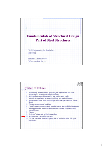
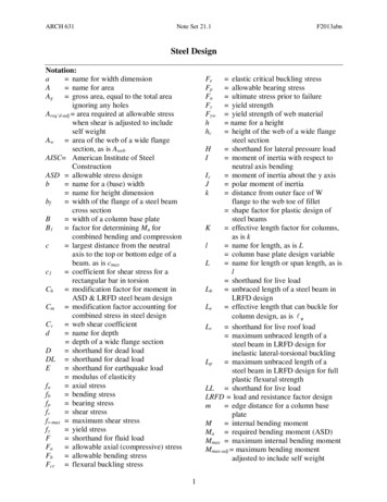
1 INTRODUCTION:THE STRUCTURAL DESIGN PROCESS1.1 PROBLEM FORMULATIONBefore starting to design a structure it is important to clarify what purpose it is to serve. Thismay seem so obvious that it need not be stated, but consider for example a building, e.g. afactory, a house, hotel, office block etc. These are among the most common structures that astructural engineer will be required to design. Basically a building is a box-like structure,which encloses space.Why enclose the space? To protect people or goods? From what? Burglary? Heat? Cold?Rain? Sun? Wind? In some situations it may be an advantage to let the sun shine in thewindows in winter and the wind blow through in summer (Figure1.1). These considerationswill affect the design.Figure 1.1 Design to use sun, wind and convectionHow much space needs to be enclosed, and in what layout? Should it be all on ground levelfor easy access? Or is space at a premium, in which case multi-storey may be justified(Figure1.2). How should the various parts of a building be laid out for maximumconvenience? Does the owner want to make a bold statement or blend in with thesurroundings?The site must be assessed: what sort of material will the structure be built on? What localgovernment regulations may affect the design? Are cyclones, earthquakes or snow loadslikely? Is the environment corrosive?1.2 CONCEPTUAL DESIGNArchitects rather than engineers are usually responsible for the problem formulation andconceptual design stages of buildings other than purely functional industrial buildings.However structural engineers are responsible for these stages in the case of other industrial1
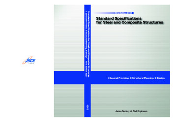
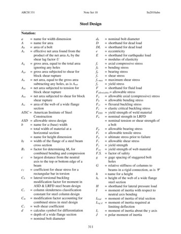
2Introductionstructures, and should be aware of the issues involved in these early stages of designingbuildings. Engineers sometimes accuse architects of designing weird structures that are notsensible from a structural point of view, while architects in return accuse structural engineersof being concerned only with structural issues and ignoring aesthetics and comfort ofoccupiers. If the two professions understand each other’s points of view it makes for moreefficient, harmonious work.Figure1.2 Low industrial building and high rise hotelThe following decisions need to be made:1. Who is responsible for which decisions?2. What is the basis for payment for work done?3. What materials should be used for economy, strength, appearance, thermal and soundinsulation, fire protection, durability? The architect may have definite ideas aboutwhat materials will harmonise with the environment, but it is the engineer who mustassess their functional suitability.4. What loads will the structure be subjected to? Heavy floor loads? Cyclones? Snow?Earthquakes? Dynamic loads from vibrating machinery? These questions are firmly inthe engineer’s territory.Besides buildings, other types of structure are required for various purposes, for example tohold something vertically above the ground, such as power lines, microwave dishes, windturbines or header tanks. Bridges must span horizontally between supports. Marine structuressuch as jetties and oil platforms have to resist current and wave forces. Then there are movingsteel structures including ships, trucks and railway rolling stock, all of which are subjected todynamic loads.Once the designer has a clear idea of the purpose of the structure, he or she can start topropose conceptual designs. These will usually be based on some existing structure, modifiedto suit the particular application. So the more you notice structures around you in everydaylife the better equipped you will be to generate a range of possible conceptual designs fromwhich the most appropriate can be selected.
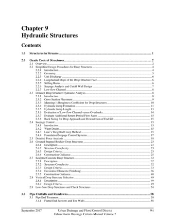
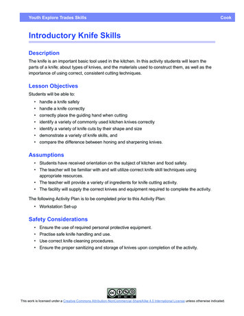
Introduction3For example a tower might be in the form of a free standing cantilever pole, or a guyed pole,or a free-standing lattice (Figure1.3). Which is best? It depends on the particular application.Likewise there are many types of bridges, many types of building, and so on.Figure1.3 Towers Left: “Tower of Terror” tube cantilever at Dream World theme park, GoldCoast. Right: bolted angle lattice transmission tower.1.3 CHOICE OF MATERIALSSteel is roughly three times more dense than concrete, but for a given load-carrying capacity,it is roughly 1/3 as heavy, 1/10 the volume and 4 times as expensive. Therefore concrete isusually preferred for structures in which the dead load (the load due to the weight of thestructure itself) does not dominate, for example walls, floor slabs on the ground andsuspended slabs with a short span. Concrete is also preferred where heat and sound insulationare required. Steel is generally preferable to concrete for long span roofs and bridges, talltowers and moving structures where weight is a penalty. In extreme cases where weight is tobe minimised, the designer may consider aluminium, magnesium alloy or FRP (fibrereinforced plastics, e.g. fibreglass and carbon fibre). However these materials are much moreexpensive again. The designer must make a rational choice between the available materials,usually but not always on the basis of cost.Although this book is about steel structures, steel is often used with concrete, not only in theform of reinforcing rods, but also in composite construction where steel beams supportconcrete slabs and are connected by shear studs so steel and concrete behave as a singlestructural unit (Figs.1.4, 1.5). Thus the study of steel structures cannot be entirely separatedfrom concrete structures.
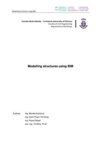
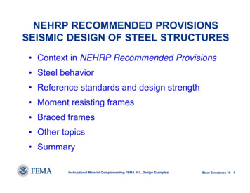
4IntroductionFigure1.4 Steel bridge structure supporting concrete deck, Adelaide HillsFigure1.5 Composite construction: steel beams supporting concrete slabin Sydney Airport car park1.4 ESTIMATION OF LOADS (STRUCTURAL DESIGN ACTIONS)Having decided on the overall form of the structure (e.g. single level industrial building, highrise apartment block, truss bridge, etc.) and its location (e.g. exposed coast, central businessdistrict, shielded from wind to some extent by other buildings, etc.), we can then start toestimate what loads will act on the structure. The former SAA Loading code AS 1170 hasnow been replaced by AS/NZS 1170, which refers to loads as “structural design actions.” Themain categories of loading are dead, live, wind, earthquake and snow loads. These will bediscussed in more detail in Chapter 2. A brief overview is given below.1.4.1 Dead loads or permanent actions (the permanent weight of the structure itself). Thesecan be estimated fairly accurately once member sizes are known, but these can only bedetermined after the analysis stage, so some educated guesswork is needed here, andnumbers may have to be adjusted later and re-checked. This gets easier with experience.
Introduction51.4.2 Live loads (imposed actions) are loads due to people, traffic etc. that come and go.Although these do not depend on member cross sections, they are less easy to estimateand we usually use guidelines set out in the Loading Code AS 1170.11.4.3 Wind loads (wind actions) will come next. These depend on the geographical region –whether it is subject to cyclones or not, the local terrain – open or sheltered, and thestructure height.1.4.4 Earthquake and snow loads can be ignored for some structures in most parts ofAustralia, but it is important to be able to judge when they must be taken into account.1.4.5 Load combinations (combinations of actions). Having estimated the maximum loadswe expect could act on the structure, we then have to decide what load combinationscould act at the same time. For example dead and live load can act together, but we areunlikely to have live load due to people on a roof at the same time as the building is hitby a cyclone. Likewise, wind can blow from any direction, but not from more than onedirection at the same time. Learners sometimes make the mistake of taking the mostcritical wind load case for each face of a building and applying them all at the sametime. If we are using the limit state approach to design, we will also apply load factorsin case the loads are a bit worse than we estimated. We can then arrive at our designloads (actions).1.5 STRUCTURAL ANALYSISOnce we know the shape and size of the structure and the loads that may act on it, we can thenanalyse the effects of these loads to find the maximum load effects (action effects), i.e. axialforce, shear force, bending moment and sometimes torque on each member. Basic analysisof statically determinate structures can be done using the methods of engineering statics, butstatically indeterminate structures require more advanced methods. Before desktop computersand structural analysis software became generally available, methods such as momentdistribution were necessary. These are laborious and no longer necessary, since computersoftware can now do the job much more quickly and efficiently. An introduction to onepackage, Spacegass, is provided in this book. However it is crucial that the designerunderstands the concepts and can distinguish a reasonable output from a ridiculous output,which indicates a mistake in data input.1.6 MEMBER SIZING, CONNECTIONS AND DOCUMENTATIONAfter the analysis has been done, we can do the detailed design – deciding what cross sectioneach member should have in order to be able to withstand the design axial forces, shear forcesand bending moments. The principles of solid mechanics or stress analysis are used in thisstage. As mentioned above, dead loads will depend on the trial sections initially assumed, andif the actual member sections differ significantly from those originally assumed it will benecessary to adjust the dead load and repeat the analysis and member sizing steps.We also have to design connections: a structure is only as strong as its weakest link and thereis no point having a lot of strong beams and columns etc that are not joined together properly.Finally, we must document our design, i.e. provide enough information so someone can buildit. In the past, engineers generally provided dimensioned sketches from which draftsmenprepared the final drawings. But increasingly engineers are expected to be able to preparetheir own CAD drawings.
2 STEEL PROPERTIES2.1 INTRODUCTIONTo design effectively it is necessary to know something about the properties of the material.The main properties of steel, which are of importance to the structural designer, aresummarised in this chapter.2.2 STRENGTH, STIFFNESS AND DENSITYSteel is the strongest, stiffest and densest of the common building materials. Spring steels canhave ultimate tensile strengths of 2000 MPa or more, but normal structural steels have tensileand compressive yield strengths in the range 250-500 MPa, about 8 times higher than thecompressive strength and over 100 times the tensile strength of normal concrete. Temperedstructural aluminium alloys have yield strengths around 250 MPa, similar to the lowest gradesof structural steel.Although yield strength is an important characteristic in determining the load carryingcapacity of a structural element, the elastic modulus or Young’s modulus E, a measure of thestiffness or stress per unit strain of a material, is also important when buckling is a factor,since buckling load is a function of E, not of strength. E is about 200 GPa for carbon steels,including all structural steels except stainless steels, which are about 5% lower. This is about3 times that of Aluminium and 5-8 times that of concrete. Thus increasing the yield strengthor grade of a structural steel will not increase its buckling capacity.The specific gravity of steel is 7.8, i.e. its mass is about 7.8 tonnes/m3, about three times thatof concrete and aluminium. This gives it a strength to weight ratio higher than concrete butlower than structural aluminium.2.3 DUCTILITYStructural steels are ductile at normal temperatures under normal conditions. This propertyhas two important implications for design. First, high local stresses due to concentrated loadsor stress raisers (e.g. holes, cracks, sudden changes of cross section) are not usually a majorproblem as they are with high strength steels, because ductile steels can yield locally andrelive these high stresses. Some design procedures rely on this duc
This book introduces the design of steel structures in accordance with AS 4100, the Australian Standard, in a format suitable for beginners. It also contains guidance and worked examples on some more advanced design problems for which we have been unable to find s