Transcription
10.23.2015PRO Lesson A03 – COMPOUND ACTION POTENTIAL: NERVE CONDUCTIONUsing the frog sciatic nerveDeveloped in conjunction with Department of Biology, University of Northern Iowa, Cedar FallsThis PRO lesson describes the hardware and software setup necessary to record Compound Action Potentials(CAP) from a dissected frog sciatic nerve. For a specific procedure on isolating and removing the frog sciaticnerve, please refer to BSL PRO Lesson A01 - Frog Preparation.Objectives:1. To record the compound action potential (CAP) of the frog sciatic nerve.2. To record the responses to sub-threshold, threshold, sub-maximal, maximal and supramaximal stimulation.3. To estimate the refractory period of the nerve.4. To explore the relationship between stimulus strength and duration.5. To determine average conduction velocity.6. To observe the effect of temperature on impulse conduction.7. To observe the impact of anesthesia on the nerve impulse.8. To examine fatigues of the nerve.Equipment: Biopac Student Lab System:o MP36 or MP35 hardwareo BSL 4.0.1 or greater software Live frog, as large as possible, in order to obtainideally 2.75 inches (7 cm) of dissected sciatic nerve Thread (nylon, cotton, or similarly absorbent thread)BSL PRO template file: “a03.gtl” AlcoholStimulator (one of the following):o BSLSTMB/Ao SS58L MP35 Low-Voltage Stimulatoro OUT3 BNC adapter for MP36 built in LowVoltage Stimulator Amphibian Ringer’s solution: dissolve in dH2O: 113mM (6.604 g/L) NaCl, 3.0 mM (0.224 g/L) KCl, 2.7mM (0.397 g/L) CaCl2, 2.5 mM (0.210 g/L) NaHCO3,pH 7.2 – 7.4, stable for months at room temperature Goggles Thermometer Examination/surgical gloves Abrasive pads (ELPAD or equivalent) Nerve blocker (ether) Cotton swabsNerve conduction chamber:o NERVE1 (with lid and agent well,) oro NERVE2 BSLCBL2A: Stimulator to nerve chamber BNCadapter cable (w/2 mm mini banana plugs)* BSLCBL4B: Nerve response recording cable (w/2mm mini banana plugs)* Glass or plastic cover for nerve chamber (if notusing BIOPAC NERVE1)*If using a non-BIOPAC nerve chamber with banana plugs, use BSLCBL3A and BSLCBL1.www.biopac.comPage 1 of 22
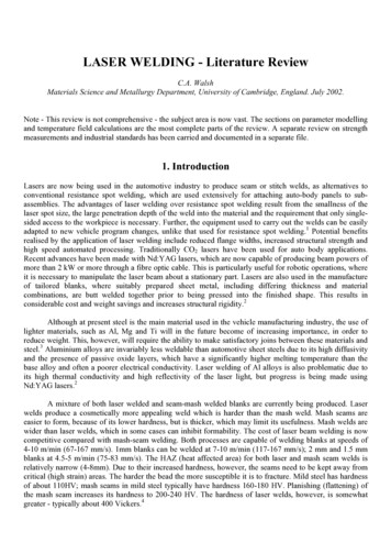
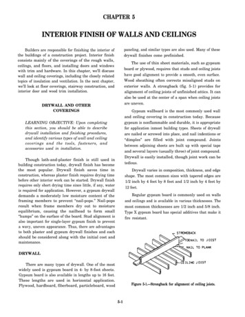
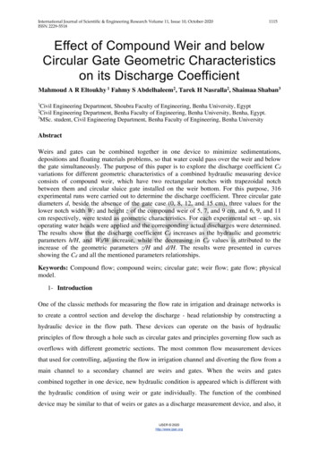
BSL PRO Lesson A03BIOPAC Systems, Inc.Background:The origin of the action potential is based on some amazing properties of the cell membrane. All cells developa membrane potential (Vm). A microelectrode with a very small tip can be carefully introduced into the cellthrough its membrane. Much research has been done to ascertain the origin of the membrane potential (Vm).Fundamentally, a cell develops a membrane voltage due to the separation of charged ions across the cellmembrane. Because of differences in concentration and the selective permeability (or conductance) of themembrane, only certain ions can cross the barrier. The separation of charge across the membrane eventuallyachieves “electro-chemical” equilibrium and at this point the resting membrane potential is established.While all cells develop a resting membrane potential, only nerve and muscle cells have the ability to change itdramatically. If the Vm changes very quickly in response to particular stimuli, this property is called excitability.The response is called an action potential. Figure 1 is a typical action potential for a single mammaliannerve cell.Action potentials travel along the surface of aneuron as a wave because of synchronizedion channel opening and closing. This motionis self-renewing and called propagation. Thestimulus first irritates one region of the neuronby opening specific ion channels and allowingpositive charges to move into the cell. Thisportion of the cell membrane becomes lessnegative, or “depolarized.” If the stimulus isstrong enough, the cell may reach thresholdand produce a significant change in the Vm(Figure 1).Figure 1In fact, the interior will become positive with respect to the exterior and is known as the action potential. Thedepolarized portion of the membrane, in turn, excites adjacent areas and they depolarize also. This processcontinues until the depolarizing wave has swept down the entire length of the neuron. Repolarization of themembrane follows behind the sweep of negativity bringing the membrane back to the resting state (Vm).Recovery of the resting Vm after excitation takes time. This is called the “refractory period.”Intracellular Action Potential recordings can give precise information about individual cells, but they are difficultto observe, and beyond the capabilities of most labs. This lesson describes an extracellular recordingtechnique that is much easier to perform, but records the compound or “summed” response from a group ofcells, which is why it is called compound action potential (CAP). Although CAP recordings provide onlyimplied information about individual and group cell activity, they are useful for gaining insight into factors thatinfluence propagation of nerve impulses in a mixed nerve.The frog sciatic nerve is essentially a bundle of hundreds of individual nerve fibers (axons) with long dendritesand axons bound by connective tissue. The sciatic nerve contains both efferent (motor) and afferent(sensory) neurons, so impulse propagation can occur in both directions simultaneously. When the sciaticnerve is dissected, the connection between each nerve cell body and its effector or receptor is severed(Figure 2).www.biopac.comPage 2 of 22
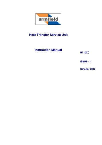
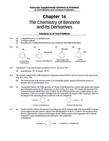
BSL PRO Lesson A03BIOPAC Systems, Inc.Figure 2If you stimulate the trunk of a nerve, you observe a CAP. Even though the stimulus ( V) is introduced andrecorded on the outside of the nerve, interior neurons will be stimulated (or recruited) because the signalspreads though the conducting fluids between neurons. The collective activity of all the axons in the nerve iscalled the nerve impulse or CAP. (Now, how do action potentials in a neuron differ from nerve impulses?)The nerve impulse can be detected with surface electrodes that are in contact with the nerve (Figure 3). Thistechnique will be used in the laboratory with a nerve chamber, which is a row of closely spaced electrodes(metal pins). The electrical activity associated with the nerve can be recorded with Biopac Student Lab system.The digital data recorder (MP36/MP35) is controlled by computer software and outputs a graph of Voltage(vertical) vs. Time (horizontal) on the display. The stimulator connects to the MP36/MP35 for synchronizationbut is also controlled by the software. The system will record and display both the stimulus and responsesignals. In this exercise, the sciatic nerve will be removed from the frog and laid across the electrode pins inthe chamber. The stimulator will deliver pulses of electricity ( V) to one point on the nerve. The nerve will alsobe in contact with a pair of recording electrodes connected to recording cable. The voltage recorded will be thedifference in voltage between the “ ” and “-” leads as the impulse moves along the nerve.Figure 3To better understand the CAP recording, first consider a single neuron or “nerve fiber” placed in the nervechamber. Figure 4 shows five “snap-shots” in time of events occurring on one neuron beginning with A andending with E. The recording is considered biphasic since it contains both positive and negativevoltage deflections.www.biopac.comPage 3 of 22
BSL PRO Lesson A03BIOPAC Systems, Inc.A. When an external stimulus exceeds a certainthreshold level, an action potential will occur,creating the nerve impulse shown in blue. Thepolarity of the impulse is negative (-) because weare measuring from the outside (opposite polarityto that inside the cell). Since both recordingelectrodes at this instant are at the same voltagepotential, it records 0 Volts.Note: It only matters that the stimulus levelexceeds the nerve fiber's threshold, because anerve impulse is generated in an all-or-nonefashion. This means that regardless of thestimulus strength above threshold strength, thecorresponding nerve impulse amplitude, durationand propagation velocity will be the same.B. The nerve impulse will propagate along the nervewith constant amplitude and velocity until iteventually passes over the “-” recording electrode,resulting in a positive (upward) voltage recording.C. Propagation will continue and a point may bereached where the nerve impulse is between the“-” and “ ” electrodes, resulting in a 0 Voltrecording (both electrodes at same voltage).D. Propagation will continue and eventually passover the “ ” electrode, resulting in a negative(downward) voltage recording.Figure 4E. At some point, the impulse propagation will becomplete, with the entire nerve fiber returned to itsresting state and since both electrodes are at thesame voltage, the recorded voltage will be zero.Since the recorded voltage is the difference betweenvoltages on the “ ” and “-” electrodes, if they arepositioned too close together (Figure 5), the recordedvoltage will be greatly reduced and may not even bevisible. Keep this in mind when positioning theelectrodes (terminal leads), as described in therecording section of this lesson.The actual CAP recording (Figure 6) is made up ofhundreds of individual neurons or nerve fibers.Because of the way electrical current spreads acrossmembranes, larger axons reach threshold in responseto relatively small signals. Consequently, the axons ofthe sciatic nerve differ in threshold; some axons willbe brought to threshold by weaker electrical stimulithan others. Increasing stimulus voltage causes moreaxons to be brought to threshold and the size of thecompound action potential increases. Thus thecompound action potential is a graded phenomenon;it is not all-or-none (remember: the action potentials ofconstituent neurons are all-or-none).www.biopac.comFigure5Figure 6Page 4 of 22
BSL PRO Lesson A03BIOPAC Systems, Inc.The stimulus with the lowest voltage ( V) producing a detectable response in the nerve or neuron is thethreshold stimulus. Any voltage below threshold is considered sub-threshold stimulus. As stimulus voltageis increased, the amplitude of response will increase until a point at which no further increase in amplitudeoccurs. The stimulus that produces this maximal response is the maximal stimulus of the nerve. Submaximal stimulus is voltages between threshold and maximal and supra-maximal stimulus are voltagesabove maximal.When a stimulus of sufficient strength is applied to the nerve preparation, a CAP is expressed. The basictemporal characteristics of a signal can be seen and calculated. The latent period is the time from stimulusapplication to neuronal initial response. This is usually a fraction of a millisecond (msec). The time tomaximum response can be measured from the initiation of the biological impulse to the peak of the signal (inmsec). The duration of the response is measured in msec from the initiation of the impulse to the time of thesignal’s completion (indicated by a return to the baseline voltage). If the time from application of the stimulusthrough the completion of the response is measured, the complete cycle time for the impulse can bemeasured. The inverse of this period can be used to estimate the maximum frequency of stimulation inpulses per milliseconds (ppmsec) or pulses per second (pps).When an action potential is produced in a neuron it is propagated away from the location where it was initiallyproduced. This motion is produced by the change in open/closed properties of ion channels in the excitablemembrane. To produce the action potential, a stimulus must open sodium channels (NaC) that are closedduring the resting potential. At threshold, the entire population of NaC in one region of the membrane will open.This produces the “ ” interior at the site of stimulation. Within a few milliseconds, the recently opened NaCclose quickly and become locked shut or “inactivated.” They cannot respond to another stimulus until theyrecover. As the NaC open to produce the action potential in a neuron, certain types of potassium (K)channels are also stimulated by the “ ” voltage change and begin to slowly open.After inactivation of the NaC, the delayed-opening of the K-channels helps return the membrane voltage to theresting potential after the action potential has passed. For a short period of time, all NaC are inactivated andonly the delayed K-channels are open. Under this condition, it is not possible for the membrane to produce asecond action potential regardless of stimulus strength. This period of inhibited excitability is known as therefractory period. There are in fact two phases to the refractory period: the absolute and the relative. Duringthe absolute refractory phase, no stimulus will produce an action potential.When threshold is reached, all NaC are activated and they cannot be stimulated any more. Also duringinactivation of NaC they cannot be stimulated. In general, the absolute refractory phase will last from thebeginning of the action potential until the first NaC regain their ability to respond to a stimulus. The relativerefractory phase reflects the length of time required for complete recovery of all the NaC in a stimulatedregion. To some degree, it will also reveal the time required for the delayed-opening K channels to close.Usually when both the Na and K channels that were involved in signal generation return to their “restingphase,” the membrane voltage returns to the resting potential and stimuli will produce a fully-developedaction potential.This time or point of complete recovery marks the end of the refractory period. The refractory properties ofion channels in the membrane control three properties of neurons and nerves. First, they produce aunidirectional pattern of signal propagation. When an action potential reaches the end of a neuron, it cannotturn around and move over an area again. Because of refractoriness, it simply dissipates. Second, when aneuron experiences a sustain depolarization it produces a sequence or volley of action potentials. Themaximum rate of signal generation is regulated by refractory properties. This is important mechanism for theencoding of information by a neuron. And Third, research on the chemical and cellular basis of learningand memory has implicated important roles for changes in the refractory period in neuronal adaptationand facilitation.The stimulator allows you to vary three aspects of the stimulus: intensity (voltage), frequency and duration.As part of this lesson you will examine the relationship between stimulus strength ( V) and duration (msec) indetermining the threshold of the nerve (Figure 7). The following four characteristics define the standardresponse characteristics of a nerve or neuron:www.biopac.comPage 5 of 22
BSL PRO Lesson A03BIOPAC Systems, Inc.Rheobase: The minimum stimulus voltagethat can produce a threshold response whenapplied for an infinitely long period of time.2 x Rheobase: Twice the rheobase voltage.Utilization Time: The stimulus duration justbelow the intersection of the rheobase with thestrength-duration curve.Chronaxie: The stimulus duration thatcorresponds to the 2 x rheobase voltage.Figure 7Biopac Student Lab PRO will record both thestimulus voltage and the nerve responsesimultaneously as shown in Figure 8.Even though the stimulus voltage is applied toone section of the output layer, because thesciatic nerve has conductive fluids in andaround it, the voltage can contact theindividual nerve fibers to produce the CAP.Because the sciatic nerve will be covered in anelectrolyte (Ringer’s solution), the stimulusvoltage will also conduct across its surface asit would a wire. The recording electrodes willpick this up and it will appear as a large “spike”occurring at the same time as the stimulus.This is stimulus artifact. The amplitude of thisartifact varies, but can be much larger than theamplitude of the CAP response.Figure 8Since the sciatic nerve consists of hundreds ofdifferent diameter fibers having differentconduction velocities, the shape of the nervepotential recorded by external electrodesreflects the average conduction velocity ofmany fibers.At a short distance between stimulating andrecording electrodes the peaks caused bydifferent fibers are impossible to distinguish.When the recording electrodes are placedfarther from the stimulating electrodes,secondary peaks may appear (Figure 9).These separate peaks are produced by actionpotentials in different size classes of axonsarriving at the recording electrode at differenttimes.Figure 9www.biopac.comPage 6 of 22
BSL PRO Lesson A03BIOPAC Systems, Inc.The technique used to measure the average conduction velocity of the fastest fibers is shown in Figure 10. Thenerve is excited by a near maximal stimulus and the time t1, between the onset of stimulus and positive peak ofthe response is measured. The recording electrodes are then moved some distance, d, and time t2 ismeasured the same way as t1.Figure 10The conduction velocity is computed from:FACTORS INFLUENCING THE CAPTemperature has a dramatic impact on chemical and biological activity. Raising or lowering ambienttemperature will change reaction rates at the atomic and molecular level. In the late part the 19th century,Svarte Arrenhius studied the impact of temperate on chemical reaction rate and developed the concept ofthermal coefficient (Q10) to describe the influence of temperature on specific physical and chemicalprocesses. The shape and motion of large macromolecules in biological systems are susceptible to thermalenergy. Since ion channels in the axon are macromolecules regulating excitability and recovery during signalproduction, the electrical properties of an excitable membrane are responsive to temperature change. Bylowering temperature, a lipid bilayer becomes less viscous and conformational changes in proteins occur withless vigor. Consequently, by simply changing the temperature of fluids around them, we can alter the electricalproperties of neurons and the nerve in subtle ways.CHEMICAL BLOCAKADE OR INHIBITIONA local anesthetic is a chemical that reversibly abolishes the transmission of sensory impulses, especially forpain, by peripheral nerve fibers in a restricted area of the body. Lidocaine (Xlyocaine), when used by a dentistrepairing teeth, blocks sodium channels in the nerve fibers that supply the teeth. The blockage prevents anaction potential from being generated and a nerve impulse from being conducted by the affected fiber.Consequently, the effect of the anesthetic is a temporary loss of pain sensation from the supplied teeth.General anesthetics are volatile compounds with high lipid solubility. Ether was the first general anestheticused for surgery at Massachusetts General Hospital in 1854. We do not know exactly how it works but you canobserve its direct effects on the isolate sciatic nerve.Instructor Note:The nerve is unlikely to survive all nine of the experiments (recording modes) listed. You should assign a set ofexperiments that can be performed within your lab period. You can assign a different set for each lab groupand then have the groups share the data files.www.biopac.comPage 7 of 22
BSL PRO Lesson A03BIOPAC Systems, Inc.Dissection Recommendations:A. If possible, connect the hardware and perform the string calibration (if required) prior to preparing anddissecting the nerve. This will minimize the time from nerve dissection to CAP recording, which willoptimize the nerve recording.B. Try not to touch the frog or the nerve directly with metal or your hands (you conduct electricity). Wearlatex gloves to help impede ion transfer. You can tie surgical thread to one end nerve (as close aspossible to the end) and use the thread for handling.C. Use glass instruments when working with the nerve. Metal instruments should not touch the nervesince they can conduct electricity.D. Leave the frog as intact as possible during the dissection procedure. Leaving the leg and muscleattached to the frog will improve circulation and preserve the unused nerve until it can be dissected.E. Use amphibian Ringer's solution rather than water to avoid osmotic stress. Apply Ringer’s to the frogand dissection area in five-minute intervals throughout the dissection.F. Place the excised nerve in a container of Ringer's such that it is completely covered. It should remain insolution until you are ready to place it on the nerve conduction chamber.G. If you will be performing the hot and cold recordings, prepare two Ringer’s solutions beforehand; onewarmed to approx. 37 C (99 F) and one refrigerated to approx. 5 C (41 F).Hardware Setup:General Cable ConnectionsIt is assumed that the MP36/35 and BSLSTMB/A (if used) are connected to their power sources but are turnedOFF. It is also assumed that the MP36/35 is connected to the host computer and that BSL 4 software has beeninstalled and is known to work with the MP unit.The connections will depend on the type of stimulator used, as shown in Figure 11. The recording cable alwaysplugs into CH 1. If you are using a non-BIOPAC nerve chamber with larger banana plugs, use BSLCBL3A(recording cable) and BSLCBL1 (stimulator BNC adapter cable).If using OUT3 (w/MP36) or SS58L (MP35)If using BSLSTMB/AFigure 11www.biopac.comPage 8 of 22
BSL PRO Lesson A03BIOPAC Systems, Inc.Connections to the Nerve ChamberIn this lesson, pictures and descriptionswere made using the BIOPAC NerveChamber (NERVE1) and the latestrevisions of the BIOPAC cables. If using anon-BIOPAC nerve chamber, otherBIOPAC cables or older revisions of thecables, the setup may look different.The recording cable has three leads; VIN (Red), VIN- (White) and Ground (Black).The stimulator cable has two leads: Stim (Red) and Ground (Black). The Groundleads from both cables must be connectedtogether.It is important to be able to cover the nervechamber. If your nerve chamber did notcome with a cover, you should make oneout of plastic or glass.Figure 12Lead placement will vary due to nerve length or as required for a specific recording procedure. The leads needonly follow the general order shown in Figure 12, which is as follows: VIN (Red) must be positioned further from the stimulator leads than VIN- (White). Stim (Red) must be at the furthest point from VIN (Red). The two Ground leads should be connected together at the next pin along the nerve fromStim (Red). VIN and VIN- may be positioned on the same side of the nerve chamber.Special Notes: There must be a tight electrical connection between the leads and the nerve chamber. If there iscorrosion on any lead or socket, lightly abrade the connectors with an abrasive pad such as theBIOPAC ELPAD. There must be a good electrical connection between the nerve and the pins in the chamber. Oneway to assure good connections is to lightly abrade the top of the pins with an abrasive pad, suchas the BIOPAC ELPAD, and then clean off any debris. Position the nerve chamber for the best possible access to it without bumping the nerve chamber orpulling on cables or leads.Turn ON the hardwareAfter all cables and leads are connected, the MP36/35 and BSLSTMB/A (if used) may be turned ON. TurningON the hardware after the connections are made minimizes the chance of instrumentation errors caused byElectrostatic Discharge (ESD) during plug-in.Software SetupLaunch the BSL PRO software and open the template file “a03.gtl” in one of two ways:a) From Startup dialog, click the PRO Lessons tab and double-click on the lesson title in the list. Ifyou do not see the lesson title, try the next opening method.b) From Startup dialog, choose the Create/Record a new experiment option, click Open Graphtemplate from disk and then click OK. Navigate to the file, select it and click Open.Enter in a unique name and click OK. A folder with that name will be created and at the end of the lesson thedata file will be automatically stored in this folder. Figure 13 shows the basic controls.www.biopac.comPage 9 of 22
BSL PRO Lesson A03BIOPAC Systems, Inc.Figure 13Note: If you do not see the Lesson Buttons upon launching the “a03.gtl” graph template, go to “Display Preferences Graph” and change the Display Style from “Tabbed” to “Windowed.”Check the assigned stimulator type noted in the journal and make sure it matches the one you are using. If itdoes not, click the Preferences button and choose the “Stimulator hardware” option. Select the properstimulator type and click OK.Stimulus Level Control:The adjustment for stimulus level will be different depending on the type of stimulator you are using. If using an external stimulator (BSLSTMB/A), you will use the knob on the stimulator and adjust thelevel according to its digital readout. If using a Low Voltage stimulator (OUT3 or SS58L), you will use the level control that is in thestimulator control panel.Figure 14This procedure assumes the user has a basic knowledge of the software which includes data selection,zooming in and out, taking measurements, and placement of event markers. Review the tutorial if necessary(see options in the Help menu).CalibrationClick “Calibrate” to “zero” the stimulator’s “Reference Out” baseline (CH 2).Test ModeThis mode is used to test the setup and data displayed will not be saved.1.Set the stimulator output level to 0.5 Volts.2.Click Test.3.Click the OFF/ON button in the output control panel a few times.Results: CH 2 (Stimulator Reference Out) baseline should be at 0 Volts. Each time the OFF/ON button isclicked, CH 2 should display a pulse.4.Click Stop.5.Click Next to proceed to the recordings.www.biopac.comPage 10 of 22
BSL PRO Lesson A03BIOPAC Systems, Inc.Recording ModesOne data file containing several recordings will be saved for this lesson. Each successive recording will beappended onto the previous one. This lesson is broken down into a sequential series of recording modes, eachof which can contain multiple recordings. Each mode sets up recording and stimulator parameters that arerequired for the specific tasks. For example, when in the Refractory Period recording mode, the stimulator willoutput two pulses instead of the single pulse output during Threshold mode. The recording mode is shown inthe far left of the lesson button toolbar.Figure 15Note: Check with your instructor to determine which of the listed tasks your lab will perform. You mayskip a recording mode by clicking Next.1. ThreadA thread can be used as an experimental control and/or to verify that there are good electrical connectionsbetween the leads and the nerve chamber. Students will see stimulus artifact but no action potential response.The artifact is created because the string has been made conductive by saturating it in Ringer's solution. Thisis identical to what happens when the nerve is used.Special Notes: Use a cotton thread to allow saturation of the Ringer's solution. Cut the thread long enough to run the full length of the nerve chamber pin array but not so long thatit hangs down into the solution. If possible, soak the thread in Ringer's solution overnight to fully saturate it.1.Place the saturated thread along the length of the nerve chamber pin array.2.Add a drop of Ringer's solution at each pin intersection using a dropper.3.Cover the nerve chamber.4.Adjust the output (stimulus) level to 0.5 Volts.5.Click Record.Results: A very brief recording will be made (stopped automatically). You should see a stimulus pulse onCH 2 and a corresponding response on CH 1. If no response is seen, select Display (menu) Autoscale Waveforms to zoom in on the data. If you still cannot see a response, increase the stimuluslevel to 1 Volt and click Record. Repeat if necessary at higher stimulus levels. If desired, click Redo todelete a previous recording.Note: The horizontal scale is set to hold the relative position. This means if you in zoom in on the areaaround the stimulus pulse, each successive recording will place the stimulus pulse in thesame position.6.Remove the string from the nerve chamber.7.Click Next to proceed to the next recording mode.www.biopac.comPage 11 of 22
BSL PRO Lesson A03BIOPAC Systems, Inc.Figure 162. ThresholdThis mode is used to record the responses to sub-threshold, threshold, sub-maximal, maximal and supramaximal stimulation. Each time the Record button is clicked, a brief recording will occur which will be longenough to capture the stimulus pulse and CAP response. At the start of the recording, a single stimulus pulsewill be output.Place Nerve in the Chamber1.Review the Dissection Recommendations listed earlier.2.Carefully place the nerve across the pins beginning with one end clearly touching the pin connected tothe Stim lead.3.Continue to lay the nerve down over the pins without stretching it.4.Move the recording cable’s VIN lead such that it is as far away from Stim yet clearly contacting thenerve. Move the VIN- lead so as to retain the ordering shown in Figure 12.5.Make sure the entire nerve is covered adequately with Ringer’s solution.6.Cover the nerve chamber to prevent evaporation and concentration of Ringer’s.Special Notes: All nerve chamber pins that are connected to the leads must be in contact with the nerve. If you tied a string to the nerve for handling, make sure that the string to nerve contact point is notbetween the Stim and VIN leads. The ends of the nerve should not hang into the chamber because they could end up contacting theexcess Ringer’s solution. Never allow the Ringer’s solution to completely fill the camber as it will cause a short circuitbetween the electrodes. If necessary, apply Ringer’s to the nerve every five minutes throughout the recording period.Usually covering the nerve chamber will prevent desiccation of the nerve.Threshold Mode Recordings1.Set or verify the stimulus Level is set to 0 Volts and click Record. This is your baseline recording whichshould display little to no artifact.2.Increase the stimulus Level by 0.1 Volts and click Record.3.Repeat Step 2 until a CAP response is observed.Note: The timing and amplitude of the CAP response will very greatly between setups as shown inFigure 17. You ma
compound action potential increases. Thus the compound action potential is a graded phenomenon; it is not all-or-none (remember: the action potentials of constituent neuron