Transcription
International Journal of Scientific & Engineering Research Volume 11, Issue 10, October-2020ISSN 2229-55181115Effect of Compound Weir and belowCircular Gate Geometric Characteristicson its Discharge CoefficientMahmoud A R Eltoukhy 1 Fahmy S Abdelhaleem2, Tarek H Nasralla2, Shaimaa Shaban31Civil Engineering Department, Shoubra Faculty of Engineering, Benha University, EgyptCivil Engineering Department, Benha Faculty of Engineering, Benha University, Benha, Egypt.3MSc. student, Civil Engineering Department, Benha Faculty of Engineering, Benha University2AbstractWeirs and gates can be combined together in one device to minimize sedimentations,depositions and floating materials problems, so that water could pass over the weir and belowthe gate simultaneously. The purpose of this paper is to explore the discharge coefficient Cdvariations for different geometric characteristics of a combined hydraulic measuring deviceconsists of compound weir, which have two rectangular notches with trapezoidal notchbetween them and circular sluice gate installed on the weir bottom. For this purpose, 316experimental runs were carried out to determine the discharge coefficient. Three circular gatediameters d, beside the absence of the gate case (0, 8, 12, and 15 cm), three values for thelower notch width W2 and height z of the compound weir of 5, 7, and 9 cm, and 6, 9, and 11cm respectively, were tested as geometric characteristics. For each experimental set – up, sixoperating water heads were applied and the corresponding actual discharges were determined.The results show that the discharge coefficient Cd increases as the hydraulic and geometricparameters h/H, and W2/W increase, while the decreasing in Cd values is attributed to theincrease of the geometric parameters z/H and d/H. The results were presented in curvesshowing the Cd and all the mentioned parameters relationships.IJSERKeywords: Compound flow; compound weirs; circular gate; weir flow; gate flow; physicalmodel.1- IntroductionOne of the classic methods for measuring the flow rate in irrigation and drainage networks isto create a control section and develop the discharge - head relationship by constructing ahydraulic device in the flow path. These devices can operate on the basis of hydraulicprinciples of flow through a hole such as circular gates and principles governing flow such asoverflows with different geometric sections. The most common flow measurement devicesthat used for controlling, adjusting the flow in irrigation channel and diverting the flow from amain channel to a secondary channel are weirs and gates. When the weirs and gatescombined together in one device, new hydraulic condition is appeared which is different withthe hydraulic condition of using weir or gate individually. The function of the combineddevice may be similar to that of weirs or gates as a discharge measurement device, and also, itIJSER 2020http://www.ijser.org
International Journal of Scientific & Engineering Research Volume 11, Issue 10, October-2020ISSN 2229-55181116will minimize each deposition upstream of weirs and minimize the needed maintenance asmost of the floating materials and sediments will pass through this combined device.Mahmoudi et al [1] developed equations to estimate the flow rate through the overflow-valvedevice in different flow conditions. This device, despite its simplicity in form, is associatedwith complexity in estimating discharge. Also, Ferro [2] reported the results of aninvestigation carried out to establish the stage – discharge relationship for a flowsimultaneously discharging over and under a sluice and broad crested gate. Al-Hamid et al.[3] used a compound weir consists of triangular weirs above rectangular contracted gates andcontracted rectangular weirs above triangular gates to discuss the effect of hydraulic andgeometrical parameters on the combined discharge and the results were presented asdischarge equations. It was found that significant errors were produced for the prediction ofthe combined discharge through the use of common discharge coefficients. Negm et al. [4]carried out experimental runs to discuss the characteristics of combined flow over a sharpcrested rectangular weir and through a gate structure below the weir. The results showed thatIJSERthe geometrical and hydraulic parameters have a significant effect on the discharge, andwithin the limitations of the experimental setup, their discharge formula was used under afree-flow condition. Negm et al. [5] conducted an experimental investigation to study thecharacteristics of the combined flow over contracted sharp crested rectangular weirs andbelow contracted sharp crested rectangular gate. A laboratory flume of (0.305 m * 0.305 m *9.00 m) dimensions was used to conduct the experiments using nineteen models on ahorizontal bed and eighteen models for sloping beds. Abbas et al. [6] investigated thecoefficient of discharge Cd for combined hydraulic measuring device consists of compoundweir (have two rectangular notches with trapezoidal notch between them) and belowsemicircular sluice gate. It was found that, the value of Cd varies from 0.427 to 0.543. AlSaadi [7] presented the results of an experimental study on the hydraulic characteristics ofweirs and combined weirs under multi cases, these cases were (rectangle weir, V-notch weir,semicircular weir, rectangular combined weir with a rectangular gate, V-notch combined weirwith a rectangular gate, semi-circular combined weir with a rectangular gate, and semicircularcombined weir with a semi-circular gate). Abdulabbas et al [8] conducted experimental runsto investigate the scour hole dimensions downstream the combined devices which consist ofweir and gate. Twelve models have been designed and every model is formed from compositeweir consists of two geometric shapes and three types of gates which are rectangular, semicircular and triangular in shape, where multi factors were studied to find out the effect ofchanging geometry for both weir and gate, discharge flowing in the flume and particle size ofIJSER 2020http://www.ijser.org
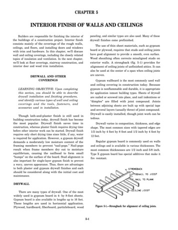
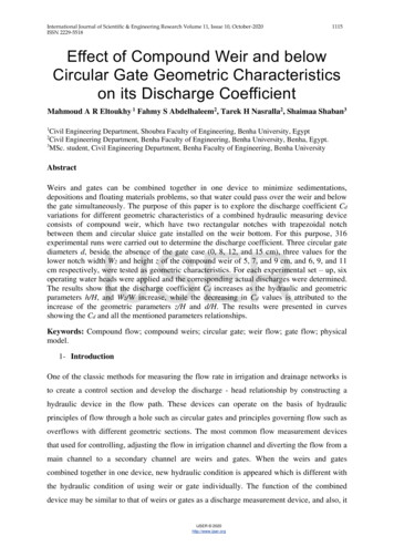
International Journal of Scientific & Engineering Research Volume 11, Issue 10, October-2020ISSN 2229-55181117bed material on the dimensions of scour hole. The experiments were conducted in alaboratory channel with dimensions of 18 m length, 1 m width and 1 m depth. Saleh and Abbas[9] investigated the discharge coefficient for combined device consists of compound weirhave two rectangular notches with trapezoidal notch between them and semicircular sluicegate to study the effect of the compound weir and gate geometric characteristics on thedischarge coefficient. Fifteen models were constructed and manufactured of Plexiglas sheet of3 mm thickness with beveled edges to 2 mm thickness for this purpose. Eltoukhy andMohammad [10] studied experimentally the velocity distributions downstream compoundweirs. The results showed that the vertical and longitudinal velocity distributions increasewith water head and with plastic bed case. The velocity distributions decrease for larger wideweir and higher downstream water depth. Rafi et al [11] implemented experimental runs inthe hydraulic laboratory considering hydraulic and geometrical variables to investigate theoverlapping between weir and gate having a parabolic shape. They reported that the weir andgate cross sectional area of flow have significant effect on coefficient of discharge ofIJSERcombined hydraulic structure. It is also very necessary to consider the effect of geometricalparameters on the coupled parabolic weir over flow and gate under flow rate. Also, the resultsproved that the weir and gate parabolic shape more efficiency as compared with regularshape. Samani and Mazaheri [12] presented a new physically based approach for estimatingthe stage discharge relationship of combined flow over the weir and under the gate for semisubmerged and fully submerged conditions.The present paper aims to study the effect of geometric characteristics of a weir equipped withlower circular gate on its discharge coefficient. The considered compound device is notpreviously reported in the available literature.2. Theoretical AnalysisThe combined free flow over a sharp crested compound weir and the below circular gate issketched in Figs. 1 and 2. The theoretical discharge equation for sharp crested compound weirQwth, which consists of two rectangular notches and trapezoidal notch between them, may bewritten as follows:22281.52.52.5𝑄𝑤𝑡ℎ 2𝑔 𝑊2 (𝑧1.5 ) 2𝑔 𝑊1 ℎ11.5 2𝑔 𝑊2 (ℎ1.52 ℎ1 ) 15 2𝑔 tan 𝜃 (ℎ2 ℎ1 )333(1)Where; Qwth: the theoretical discharge over the compound weir, h, h1, and h2: the height ofwater above the upper, middle and lower notches of the compound weir, z: is the height of theIJSER 2020http://www.ijser.org
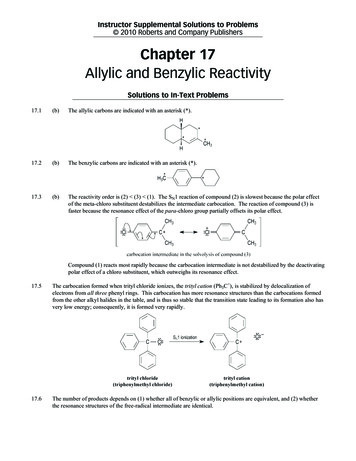
International Journal of Scientific & Engineering Research Volume 11, Issue 10, October-2020ISSN 2229-55181118lower notch, W1: width of the upper notch of the compound weir. W2: width of the lowernotch of the compound weir. g: the gravitational acceleration. ө: the angle of the crest of thecompound weir.Fig. 1 Sketch of the combined weirFig. 2 Model sample of combined weirOn the other hand, the theoretical discharge through the circular gate Qgth may be written as:IJSER𝜋𝑑𝑄𝑔𝑡ℎ 𝑑2 2𝑔 (ℎ 𝑦 )42(2)Where: Qgth: the circular gate theoretical discharge, d: the circular gate diameter, and y is thedistance between the lower notch sill and the circular gate.The total theoretical discharge Qth is calculated by combining the two equations 1 and 2 asfollows;Qth Qwth Qgth(3)And hence, the actual discharge Qact can be written as;Qact Cd x Qth 𝜋4Cd22281.52.52.5( 2𝑔 𝑊2 (𝑧1.5 ) 2𝑔 𝑊1 ℎ11.5 2𝑔 𝑊2 (ℎ1.52 ℎ1 ) 15 2𝑔 tan 𝜃 (ℎ2 ℎ1 ) 333𝑑𝑑 2 2𝑔 (ℎ 𝑦 ))(4)2The functional relationship of the discharge coefficient Cd can be written as;Cd ƒ(H, h, h1, h2, Z, y, d, b, W1, W2, g, ρ, µ, σ)IJSER 2020http://www.ijser.org(5)
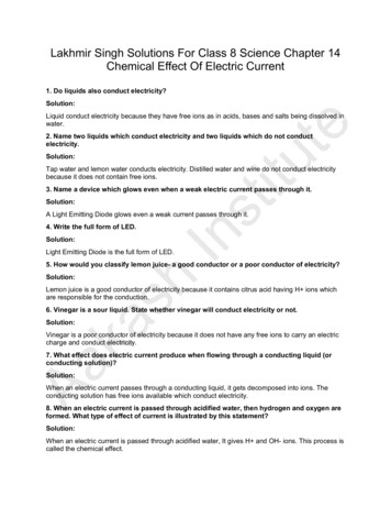
International Journal of Scientific & Engineering Research Volume 11, Issue 10, October-2020ISSN 2229-55181119Where: b: is the flume width (38.5 cm), ρ: the water density, µ: dynamic viscosity, σ: surfacetension.Based on Eq. (5) and employing Buckingham π – theorem the following relationship wasobtained;𝑊2𝐶𝑑 𝑓 (𝑊,ℎ𝐻,𝑧𝐻,𝐻𝑑, 𝑅𝑒 , 𝑊𝑒 )(7)In which Re and We are Reynolds and Weber numbers respectively and assumed to beneglected for combined devices at tested parameters.3. Experimental Setup and MethodologyThe experimental runs were carried out in the Hydraulics Laboratory, Benha Faculty ofEngineering, Benha University, Egypt. A zero slope flume with smooth concrete bed andPlexiglas walls was used for achieving the purpose of this paper. The flume has width of 0.4IJSERm, height of 0.6 m, and a length of 15.0 m as shown in Fig. 3. A pump was used to pumpwater from the ground tank of dimensions (5.5, 4.4, and 1 m) to the flume, using control valveto control the pumped discharge. The flume has an adjustable tailgate at the downstream endto produce the desired flow conditions. The pumped discharge was measured by calibratedflow meter and point gauge was used for measuring the water levels.The experimental run procedure was devised to accurately determine the head–dischargerelationship across multiple compound weir and circular gate geometric characteristics. Thefollowing steps were followed for each experiment1- Set up the first compound weir without circular gate and turn on the pump to pumpwater into the flume with adjusting the controlling valve for the required head andrecording the corresponding discharge.2- Adjust the controlling valve to have new head and also record the correspondingdischarge five times.3- Repeat steps 1 and 2 for lower weir part height z of 6 cm with three widths of 5, 7, 9cm.4- Repeat step 3 for two another values of z of 9 and 11 cm.5- Repeat steps from 1 to 4 using circular gate diameters of 8, 12, and 15 cm.6- After each run the pump should be turned off.IJSER 2020http://www.ijser.org
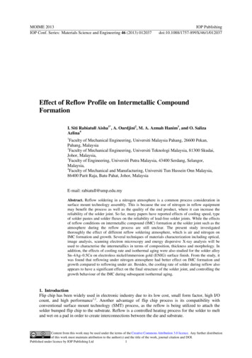
International Journal of Scientific & Engineering Research Volume 11, Issue 10, October-2020ISSN 2229-55181120The experimental program is summarized for each circular gate diameter d of 0, 8, 12, and 15cm three values of the lower notch of a height z of 6, 9, and 11 cm, for each z three values ofFig. 3 Plan and elevation of the flume layoutthe lower notch width W2 of 5, 7, and 9 cm Which, in turn, uses six values for the water headfor each W2 value.IJSER4. Results and Discussionℎ𝑊2𝐻𝑊The effect of the hydraulic parameters ,,𝑧𝐻,𝐻𝑑on Cd was investigated in this section.4.1 Discharge Coefficient Variation Cd with the water head ratio h/HFirstly the discharge coefficient Cd variation with the water head ratio h/H was discussed.Through the analysis of all experimental runs, it was found that for constant circular gatediameter ratio d/H, lower notch width ratio W2/W, and lower notch height h/H, the dischargecoefficient Cd increases as the water head ratio h/H increases. The increase in Cd in allcircular gate diameters beside the case of no circular gate (d 0) has the same trend, Figs 4to 15. For example for d/H 0.24, z/H 0.18 and W2/W 0.18 increasing h/H from 0.18 to0.278 results in increasing in Cd from 0.4978 to 0.569, which means that 54.44% increasingin h/H results in 14.3% increasing in Cd. The range of the discharge coefficient Cd and itsaverage values for different h/H are for d/h 0 Cd ranges from 0.5096 to 0.9124 withaverage value of 0.711, for d/h 0.16 Cd ranges from 0.4548 to 0.7134 with average valueof 0.584, for d/h 0.24 Cd ranges from 0.4562 to 0.6537 with average value of 0.5549, ford/h 0.3, Cd ranges from 0.3905 to 0.5809 with average value of 0.4857.4.2 Discharge Coefficient Variation Cd with the Lower Notch Width Ratio W2/WAlso, Figs 4 to 19 show that for constant circular gate diameter ratio d/H, water head ratioh/H, and lower notch height z/H, the discharge coefficient Cd increases as the lower notchIJSER 2020http://www.ijser.org
International Journal of Scientific & Engineering Research Volume 11, Issue 10, October-2020ISSN 2229-55181121width increases for all circular gate diameters beside the case of absence of the circular gate(d 0). For instance for d/H 0.24, h/H 0.3, and z/H 0.18, the discharge coefficient CdFig. 4 Variation of Cd with Water Head, z/H 0.22, d/H 0IJSERFig. 5 Variation of Cd with Water Head, z/H 0.18, d/H 0IJSER 2020http://www.ijser.org
International Journal of Scientific & Engineering Research Volume 11, Issue 10, October-2020ISSN 2229-5518Fig. 6 Variation of Cd with Water Head, z/H 0.12, d/H 0Fig. 7 Variation of Cd with Water Head, z/H 0.22, d/H 0.16IJSERFig. 8 Variation of Cd with Water Head, z/H 0.18, d/H 0.16Fig. 9 Variation of Cd with Water Head, z/H 0.12, d/H 0.16IJSER 2020http://www.ijser.org1122
International Journal of Scientific & Engineering Research Volume 11, Issue 10, October-2020ISSN 2229-5518Fig. 10 Variation of Cd with Water Head, z/H 0.22, d/H 0.24IJSERFig. 11 Variation of Cd with Water Head, z/H 0.18, d/H 0.24Fig. 12 Variation of Cd with Water Head, z/H 0.12, d/H 0.24IJSER 2020http://www.ijser.org1123
International Journal of Scientific & Engineering Research Volume 11, Issue 10, October-2020ISSN 2229-5518Fig. 13 Variation of Cd with Water Head, z/H 0.22, d/H 0.3IJSERFig. 14 Variation of Cd with Water Head, z/H 0.18, d/H 0.3Fig. 15 Variation of Cd with Water Head, z/H 0.12, d/H 0.3IJSER 2020http://www.ijser.org1124
International Journal of Scientific & Engineering Research Volume 11, Issue 10, October-2020ISSN 2229-5518Fig. 16 Variation of Cd with W2/W, for h/H 0.32, d/H 0IJSERFig. 17 Variation of Cd with W2/W, for h/H 0.3, d/H 0.16Fig. 18 Variation of Cd with W2/W, for h/H 0.3, d/H 0.24IJSER 2020http://www.ijser.org1125
International Journal of Scientific & Engineering Research Volume 11, Issue 10, October-2020ISSN 2229-55181126Fig. 19 Variation of Cd with W2/W, for h/H 0.3, d/H 0.3increases from 0.5366 to 0.6162 as the lower notch width ratio W2/W increases from 0.13 to0.23, this means that Cd increases by 14.8% as a result of 76.92% increasing in W2/W.IJSER4.1 Effect of Lower Notch height Ratio z/H on the Discharge Coefficient CdOppositely, the analysis of the experimental results show that for constant circular gatediameter ratio d/H, water head ratio h/H, and lower notch width W2/W, the dischargecoefficient Cd decreases as the lower notch height increases, Figs 20 to 23. It was found thatfor d/H 0.3, h/H 0.3, and W2/W 0.18, increasing of the lower notch height ratio z/Hfrom 0.12 to 0.22 leads to decreasing in the value of Cd from 0.6 to 0.5389, which meansthat the discharge coefficient Cd has 11.34% decreasing as a result of 83.33% increasing inthe lower notch height ratio z/H.4.2 Effect of the Circular Gate Diameter Ratio d/H on the Discharge Coefficient CdFigs 24 and 25 show that, the presence of circular gate below the compound weir has an effecton the overall discharge coefficient Cd for the same values of water head ratio h/H, lowernotch width W2/W, and the lower notch height z/H. It was found that increasing the circulargate diameter ratio d/H results in decreasing in the value of the discharge coefficient Cd. Forexample, changing the value of d/H from 0.16 to 0.3 leads to decreasing of Cd value from0.655 to 0.566, this means that 87.5% increasing in d/H results in 15.7% decreasing in thevalue of Cd.IJSER 2020http://www.ijser.org
International Journal of Scientific & Engineering Research Volume 11, Issue 10, October-2020ISSN 2229-5518Fig. 20 Variation of Cd with z/H, for h/H 0.32, d/H 0IJSERFig. 21 Variation of Cd with z/H, for h/H 0.3, d/H 0.16Fig. 22 Variation of Cd with z/H, for h/H 0.3, d/H 0.24IJSER 2020http://www.ijser.org1127
International Journal of Scientific & Engineering Research Volume 11, Issue 10, October-2020ISSN 2229-55181128Fig. 23 Variation of Cd with z/H, for h/H 0.3, d/H 0.3IJSERFig. 24 Variations of discharge coefficient Cd with the circular gate diameter ratio d/Hfor W2/W 0.18 and h/H 0.25Fig. 25 Variations of discharge coefficient Cd with the circular gate diameter ratio d/Hfor z/H 0.22 and h/H 0.25IJSER 2020http://www.ijser.org
International Journal of Scientific & Engineering Research Volume 11, Issue 10, October-2020ISSN 2229-551811295. ConclusionsBased on the analysis of the experimental results the following main conclusions wereconcluded:1- There are effects of the compound weir with below circular gate geometriccharacteristics on the discharge coefficient Cd.2- For all experimental results, the coefficient of discharge Cd increases as the hydraulicwater head h increases with the same trend.3- As the width of the lower notch of the compound weir W2 increases for constantvalues of water head h, circular gate diameter d, and lower notch height z, thedischarge coefficient Cd also increases.4- Increasing the lower notch height z for the same water head h, circular gate diameter d,and the lower notch width W2, results in decreasing the discharge coefficient Cd.5- The circular gate diameter d increasing results in decreasing of Cd for the same lowerIJSERnotch of the compound weir W2, lower notch height z, and water head h.NotationsCd: discharge coefficient ( - ).d: The circular gate diameter (L).g: The gravitational acceleration (LT-2).h: Total head (L).h1, h2: height of water above the upper and middle notches of the compound weir (L).W: Width of the flume (L).W1: Width of the upper rectangular notch (L).W2: Width of the lower rectangular notch (L).Qth: Free combined theoretical discharge (L3T-1).Qact: Actual discharge (L3T-1).Qwth: Compound weir theoretical discharge (L3T-1).Qgth: Circular gate theoretical discharge (L3T-1).Re: Reynolds's number ( - ).We: Weber number ( - ).X: Height of the crest (L).Y: Distance between the lower edge of weir crest and the gate top (L).Z: Height of the lower notch of the compound weir (L).µ: Dynamic viscosity (ML-1T-1).ρ: Water density (ML-3).σ: Surface tension (MT-2).ө: The angle of the crest for trapezoidal notch ( - ).References1. B. Mahmoudi, Hossein K. S. and Javad F. (2015) "Estimation of overflow-valve flowrate for free, semi-submersible and submersible flow types based on discharge-headIJSER 2020http://www.ijser.org
International Journal of Scientific & Engineering Research Volume 11, Issue 10, October-2020ISSN 2229-55182.3.4.5.6.7.8.1130application", 10th International Congress of Civil Engineering, Faculty of CivilEngineering, Tabriz May 6-17, 2010Ferro V. (2000) "Simultaneous flow over and under a gate", Journal of Irrigation andDrainage Engineering, ASCE; 126(3):190–3.Al-Hamid A. A., Negm A. M., Al-Brahim A. M. (1997) , " Discharge Equation forProposed Self Cleaning Device ", J. King Saud Univ., Vol. 9 , Eng. Sci. (1), pp. 13 –24.Negm, A. M., Al-Brahim A. M.; Alhamid A. A. (2002) "Combined-free flow overweirs and below gates", J. of Hydraulic Research, 3, 359–365.Negm A. M. (2002) "Discussion of analysis and formulation of flow throughcombined V – notch – gate – device", J. of Hydraulic Research, Vol. 40 , No. 6 , pp.755 –765.Abbas H. A. (2014) "A study of flow over different opening of combined weirs andbelow gates", M.Sc. Thesis, University of Kufa, Faculty of Engineering.Al-Saadi A. K. I. (2013) "Study coefficient of discharge for a combined free flow overweir and under gate for multi cases", Euphrates Journal of Agriculture Science – Vol.5, No. 4, pp. 26-35.F. Abdulabbas H., Saleh I. K., and Hassan A. O. (2016) "Determining the coefficientof discharge due to flow over composite weir and below gates", Kufa Journal ofEngineering Vol. 7, No. 1, P.P. 115-128.IJSER9. Saleh I. K., and Abbas H. A. (2013) "Study the free flow over compound weir andbelow semi circular gate", International Journal of Scientific & Engineering Research,Volume 4, Issue 10.10. M. A. R. Eltoukhy and Mohammad I. (2015) "Velocity distribution downstreamcompound weirs" Australian Journal of Basic and Applied Sciences, 9(1), Pages: 23824511. Rafi M. Q., I. A. Abdulhussein, Qusay A. M., and Muna A. H. (2018) "Experimentalstudy of coupled parabolic weir over flow and gate under flow rate", Journal ofInformation Engineering and Applications Vol.8, No.4.12. Samani M.V. Jamal., Mazaheri, M. (2007), "Combined flow over weir and under gate"7th Iranian hydraulic conference, Power and Water University of Technology, Tehran,Iran, November, 81-86IJSER 2020http://www.ijser.org
The considered compound device is not previously reported in the available literature. 2. Theoretical Analysis The combined free flow over a sharp crested compound weir and the below circular gate is sketched in Figs. 1 and 2. The theoretical discharge equati