Transcription
Disconnecting Circuit BreakersBuyer’s and Application Guide
Edited byABB ABHigh Voltage ProductsDepartment: Marketing & SalesLayout, 3D and images: Mats Findell, Karl-Ivan GustavssonSE-771 80 LUDVIKA, Sweden2 Buyer’s and Application Guide ABB Disconnecting Circuit BreakersTel: 44 (0)191 490 1547Fax: 44 (0)191 477 5371Email: northernsales@thorneandderrick.co.ukWebsite: www.cablejoints.co.ukwww.thorneanderrick.co.uk
Table of tchgear specification7Availability10Switchgear single line philosophy15Design19Standards and testing31Environmental aspects33Substation design36Cost optimizing41Processes and support42Inquiring and ordering44Protection and control IEDs46ABB Disconnecting Circuit Breakers Buyer’s and Application Guide 3
IntroductionCompact air insulated HV switchgear with Disconnecting Circuit BreakersABB has a century-long experience of building substations for high voltage systems.In time with developing, designing and manufacturing of all vital switchgear apparatus also the switchgear design has been improved through the years.One important step in the switchgear design during the latest years is that ABB’swell known high performance circuit breakers now also are available as Disconnecting Circuit Breakers. This means that the disconnecting function is included inthe circuit breaker and no separate disconnectors are necessary. By this move it isnow possible to build substations with minimized need of maintenance and space,low failure rate, increased safety and low Life Cycle Cost, i.e. Compact Air InsulatedSwitchgear.Product rangeDisconnecting Circuit Breaker, DCB, can be delivered as separate apparatus orincluded in deliveries of complete switchgear bays.TypeLTB 72.5LTB 145Rated voltage, kV72.5145170 - 300362 - 420550Rated current, A31503150400040004000Circuit breaking current, kARated frequency, HzHPL 170 - 245 HPL 362 - 420HPL 550404050636350/6050/6050/6050/6050Bay designDCB use a circuit breaker support structure, on which also earthing switch andcurrent transformer can be mounted. Further more a complete factory made busbarstructure, with necessary primary electrical connections can be included.4 Buyer’s and Application Guide ABB Disconnecting Circuit Breakers
IntroductionLine Entrance ModuleA separate structure called Line Entrance Module, LEM, is available for supportingapparatus, which are not suitable to be erected on the circuit breaker structure. Thebreaker structure together with a LEM, are normally the only structures needed tohouse the HV-apparatus in a switchgear bay, built with DCB.Primary switchgear apparatusABB offers a complete range of primary apparatus for use in Air Insulated Switchgear. Further information will be found in the Application and Buyers Guide for eachproduct according to table below.Buyers GuideApplication GuideLive Tank Circuit BreakersProduct1HSM 9543 22-00en1HSM 9543 23-00enOutdoor Instrument Transformers1HSM 9543 42-00en1HSM 9545 40-00enSurge Arresters1HSM 9543 12-00en-AbbreviationsIn this document abbreviations according to the list below are used.CBCircuit BreakerDCBDisconnecting Circuit BreakerDSDisconnecting SwitchESEarthing Switch/Grounding SwitchSASurge ArresterCTCurrent TransformerCVTCapacitor Voltage TransformerVTVoltage TransformerPIPost InsulatorBBBusbarPTPower TransformerAISAir Insulated SwitchgearGISGas Insulated SwitchgearSF6Sulphur hexafluoride gasOHLOver Head LineCLCable LineSLDSingle Line DiagramLEMLine Entrance ModuleCCCCentral Control CabinetMDFManual Disconnecting FacilityIEDIntelligent Electronic DeviceMVMedium VoltageHVHigh VoltageS/SSubstationLCALife Cycle AssessmentLCCLife Cycle CostABB Disconnecting Circuit Breakers Buyer’s and Application Guide 5
DefinitionsSpecial definitions used in this document.For definitions in general see IEC 60050.Disconnecting Circuit BreakerCircuit Breaker with integrated disconnector function.Interlocking of unintentional operation and blocking of closingfunction is integrated.Line Entrance ModuleStructure for supporting one or more switchgear apparatus suchas Voltage Transformer, Surge Arrester and Earthing Switch.Manual Disconnection FacilityA facility for manual disconnection of an apparatus, i.e. DCBor CT, in case of failure or for maintenance. Opening a boltedpredefined connection normally performs the disconnection.AvailabilityThe fraction of time that the electric power is available at a(at a certain point of a network) certain point in the network Availability depends on both planned and unplanned outages(maintenance and repair)UnavailabilityThe fraction of time that the electric power is not available at a(at a certain point of a network) certain point of a network Often expressed in hours per yearReliabilityThe probability of failure-free supply of power at a certain point(at a certain point of a network) of a network during a specified period of time The reliability concept only considers the system’s ability tofunction correctly when it is in service, i.e. interruptions dueto planned maintenance are not consideredUnreliabilityThe probability that one or more interruptions of the power sup-(at a certain point of a network) ply will occur at a certain point of a network during a specifiedperiod of time Often expressed as expected number of interruptions per100 yearsIntelligent Electronic DeviceUnit equipped with a processor used for protection and controlof electrical systems.SymbolsIn this document symbols as below are used in Single Line Diagrams.LegendCircuit breakerDisconnectorDisconnecting Circuit BreakerVoltage transformerCurrent transformerSurge arresterEarthing switch6 Buyer’s and Application Guide ABB Disconnecting Circuit Breakers
Switchgear specificationA complete Switchgear specification contains among other parts,specification of the primary electric apparatus and systems.Optimization of overall costs is a necessary measure in the deregulatedenergy market. The optimization of substations and their development isan objective continuously pursued by ABB. The focus is set on functionalrequirements, reliability and cost over the total life cycle.Apparatus specificationThe conventional way is to in detail specify all the equipment and the substationscheme. All apparatus are specified with quantity and data. Also the scheme, whichoften is based on traditional thinking, is fixed. In this case the asset owner getequipment which is exactly what he wants to have and what he is used to buy. Thisway of specifying the equipment normally gives no alternatives to propose othersolutions with better performance to lower the Live Cycle Cost.To open up for other solutions sometimes a clause saying that bidder are free topropose other equipment, is added to the inquiry.Functional specificationThe main task for a substation is to transfer power in a controlled way and to makeit possible to make necessary switching/connections in the grid. Thereby anotherway of specifying the equipment when planning a new plant or refurbish an old, canbe to make a functional specification.In this case the bidder is free to propose the best solution taking in account all thepossibilities that can be gained by using the best technique and the latest developed apparatus and systems, in combination with the requirements set up for thesubstation and the network.For example, basic requirements in a functional specification can be: Number and type of system connectionsSystem electrical dataEnergy and transfer path through the systemUnavailability related costsBased on the functional specification ABB often can propose an alternative solution, which gives better performance to considerable lower costs.To back up the decision-making, availability calculations, life cycle cost calculations,environmental influence report etc. can be provided by ABB.As the supplier takes a greater part of the design, it is important that all surroundingquestions as scope of supply, demands from authorities, special design conditionsetc. are known in the beginning of the project.ABB Disconnecting Circuit Breakers Buyer’s and Application Guide 7
Switchgear specificationExample of apparatus specificationInquiry:Please quote for apparatus for a 132 kV switchgear in 5 bays according to specification and enclosed single line diagram:5High Voltage Circuit Breaker 145 kV, 3150 A, 31.5 kA12Motor operated Disconnector 145 kV, 2000 A, 31.5 kA with integrated motor operatedEarthing Switch6Current Transformer 145 kV, 400/5/5/5/5 A. Core data 9Current Transformer 145 kV, 2000/5/5/5/5 A. Core data 12Voltage Transformer 145 kV, 132000/ 3:110/ 3:110/3 V. Core data .12Surge Arrester 132 kV 132 kV, 2000 A, 31.5 kALine 1T1T2Line 2Bus couplerThe suppliers will quote for their best prices for the apparatus and the customercan pick apparatus with the lowest price from different suppliers. The customer willhence have a cost optimized set of apparatus.8 Buyer’s and Application Guide ABB Disconnecting Circuit Breakers
Example of functional specificationInquiry:Please quote for one 132 kV switchgear with 2 incoming lines and 2 transformerfeeders.An existing line shall be cut up and connected to the substation.Maximum energy transfer through the substation is 120 MVA.Power can flow in either direction. Maximum Ik 21 kA.Transformer data 132/11 kV, 40 MVA, U k 8%Planned maintenance can be done in low load periods but one of the transformers must always bein service.132 kV, 2000 A, 31.5 kALine 1T1SectionalizerT2Line 2In this case ABB will quote a solution with Disconnecting Circuit Breakers, whichwill give an optimized total cost. The customer will have a quotation of completeswitchgear with a minimum of apparatus and high availability.The Single Line Diagram shows a solution with Disconnecting Circuit Breakers.ABB Disconnecting Circuit Breakers Buyer’s and Application Guide 9
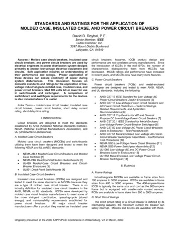
AvailabilityAvailability and reliabilityA major concern of a substation owner or operator is to minimize outages causedby scheduled maintenance, as well as repair work after possible failures. Ways toachieve this goal is equipment with low maintenance requirements, and suitablesubstation configurations. The “quality” of a certain substation in this respect isoften expressed as availability (or unavailability). The availability, e.g. of an outgoing bay in a substation, is the fraction of time that electric power is available at thatpoint. The unavailability, i.e. the fraction of time that electric power is not available,is normally expressed in hours per year.Another major concern is to avoid any blackouts for power consumers, or loss ofconnection e.g. to generating power stations. Such events are entirely related tounplanned outages due to faults (since planned maintenance would not be allowedto give such consequences). The “quality” of a certain substation in this respect isoften expressed as reliability (or unreliability). The reliability, e.g. of an outgoing bayin a substation, is the probability of failure-free supply of power at that point duringa specified period of time. The unreliability may be expressed as expected numberof interruptions per years, or as outage time in hours per year.Failure and maintenance rateEvolution of circuit breakers and disconnectorsDevelopment in CB technology has lead to significant decrease of maintenance andincrease of reliability. Maintenance intervals requiring de-energizing of the primarycircuit, of modern SF6 CBs is 15 years or more. At the same time development ofopen air DSs has focused around cost reductions by optimizing the material used,and has not given significant improvements in maintenance requirements and reliability. The maintenance interval for open-air DS main contacts is in the order of 2-6years, differing between different users and depending on the amount of pollutiondue to industrial activities and/or “natural” pollution such as sand, salt.Bulk oil breakersAir blast breakersDisconnectors withopen contactsMinimum oil breakersSF6 Circuit breakers195010 Buyer’s and Application Guide ABB Disconnecting Circuit Breakers2010
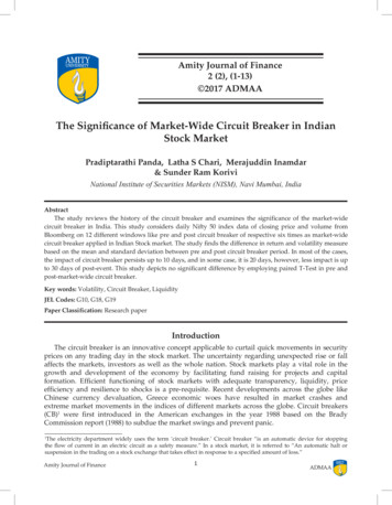
Reliability of CBs has increased due to evolution of primary breaking technology,from air blast to minimum oil, and into today’s SF6 type of CBs. At the same timethe number of series interrupters has been reduced and today live tank CBs up to300 kV are available with only one interrupter per pole. Removal of grading capacitors for live tank CBs with two interrupters has further simplified the primary circuitand thus increased the reliability. Today CBs up to 550 kV are available withoutgrading capacitors, enabling the development of DCBs up to this voltage level. Operating mechanisms for CBs have also improved going from pneumatic or hydraulicto spring type leading to more reliable designs and less maintenance.CalculationsComputer software for availability and reliability calculations is available within ABB.This makes it possible to compare different substation solutions. It is easily foundthat configurations containing conventional disconnectors in most cases give ahigher unavailability and unreliability than configurations with DCBs.Improved availability with DCBA typical power path through a substation may be divided into three main parts:line, power transformer and switchgear. Lines and power transformers have relatively high maintenance requirements. They are the dominating cause for maintenanceoutages in substations supplied by single radial lines, or with only a single transformer. In such cases maintenance of switchgear equipment is of secondary importance. On the contrary, if power can be supplied from more than one direction andthe substation is equipped with parallel transformers, the overall unavailability of thesubstation, due to maintenance, may be directly related to the switchgear equipment. Decisive factors are then the HV equipment used, as well as the configuration(single line diagram) of the substation.The dominating reason for unavailability of a certain part of a substation is (scheduled) maintenance.In the past when CBs were mechanically and electrically complicated and thereforeneeded a lot of maintenance the focus was on how to isolate the CBs for maintenance and keeping the other parts of the substation in service. The substationswere accordingly built with CBs surrounded by a lot of DSs to make it possible toisolate and maintain the CBs. Now, since modern CBs need less maintenance thanconventional DSs, it gives better results to use DCBs.As an example, a comparison is made between a traditional double busbar solution with separate CBs and DSs versus a sectionalized busbar solution with DCBsincluding manual disconnecting facilities MDF. The 132 kV substation has fouroverhead lines, two power transformers and one bus-coupler or bus-section CB.Maintenance intervals assumed were 5 years for open air DS and 15 years for CBand DCB. Introduction of the DCB thus reduces the average unavailability due tomaintenance from 3.1 to 1.2 hours per year.ABB Disconnecting Circuit Breakers Buyer’s and Application Guide 11
AvailabilityOutage duration (hrs/year)4.03.12.01.20CBs DSs12 Buyer’s and Application Guide ABB Disconnecting Circuit BreakersDCBs
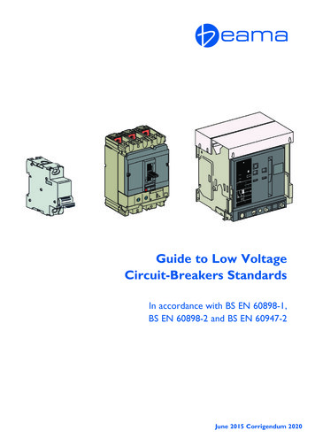
The reduction of maintenance activities will give the following advantages: More satisfied consumers, depending on substation/network topology the maintenance can lead to loss of power supply to some consumers Less risk for system disturbances (black-outs) since the risk for primary faultsduring a maintenance situation is higher than during normal service (people inthe substation) together with a “weaker” system due to the maintenance (not allequipment in service) Less cost for manpower to make the actual maintenance work at site Higher personnel safety since all work in the substation high voltage system isa potential risk for injury of the personnel due to electrical shock, falling fromheights, etc.Improved reliability with DCBFor single line configurations with only one CB per bay, a primary fault on one of theoutgoing objects plus CB failure for that bay would lead to de-energization of onebusbar section. A failure in the bus-section or bus-coupler breaker will lead to lossof the whole substation.For important substations it might not be accepted from system security perspectiveto have a risk of loosing the whole substation at a primary fault. To make the substation “immune” against busbar faults and to minimize the disturbance if a CB fails toopen at a primary fault, 1 ½-breaker or 2-breaker configurations can be used.As an example, consider a typical 420 kV substation with three OH-lines, two powertransformers and one shunt reactor. A comparison is made between a traditionaltype of solution with CBs and DSs versus a solution with DCBs including manualdisconnecting facilities MDF.ABB Disconnecting Circuit Breakers Buyer’s and Application Guide 13
AvailabilityOutage duration (hrs/year)Outages of an incoming/outgoing bay due to faults in the switchgear are shown inthe diagram. Such unplanned outages may be very problematic and lead to unacceptable loss of power supply to consumers. Failure frequency input are taken frominternational statistics sources such as CIGRÉ, which gather information from actualapparatus in service. Since the DCB is very similar to a traditional CB, failure statistics is assumed the same for CB and DCB. Introduction of the DCB thus reducesthe outages with 50%.0.30.190.20.090.1{50%0CBs DSsDCBsThe examples shown are very typical. Substation solutions with DCB generally havemuch improved availability and reliability, compared to traditional solutions.14 Buyer’s and Application Guide ABB Disconnecting Circuit Breakers
Switchgear single line philosophyWhen designing a new substation a lot of considerations have to be taken. One ofthose is the Single Line Diagram (SLD). When elaborating the SLD the main goalsare to create a solution, which gives highest possible safety for the staff and optimalservice security. Many factors such as the load, the surrounding power network, effects of power loss, reliability and maintenance need for apparatus etc. are influencing the final decision.Traditional approachBy tradition the most important aspect has been to isolate the circuit breaker in asystem for maintenance or repairing. Examples of traditional SLD are shown below.Common for these is that the circuit breaker easily can be isolated without affecting the power flow in the busbar and, when bypass DS or transfer bus is used, noteither in the actual load.Single busSingle busbypass DSDouble busSingle bus transfer busDouble bus transfer busOn the other hand, if a CB in such a system fails to open, all the busbars have to bedeenergized before the CB can be isolated.Furthermore even the disconnectors had to be maintained and to make that possible without taken the complete S/S out of service, double busbars were introduced.I.e. the main reason for double busbar systems is to allow DS maintenance.ABB Disconnecting Circuit Breakers Buyer’s and Application Guide 15
Switchgear single line philosophyNew possibilitiesAs earlier shown under chapter Availability, modern SF6 CBs have better maintenance and failure performance than DSs. That means that the traditional way ofbuilding S/S with many busbar systems and DSs rather decrease the availabilitythan increase it. Taking only above into consideration the best way to increase theavailability is to delete all DS and only use CBs. However, due to safety aspects adisconnector function is necessary. In a Disconnecting Circuit Breaker this disconnection function is integrated in the circuit breaker and it is then possible to designDS free S/S solutions.DCB is suitable to be used in systems as: Single busbar systemSectionalized single busbar systemDouble busbar/double breaker systemRing bus systemBreaker and a half systemIf double busbar or transfer bus system is a demand it can preferably be replacedby a double busbar/double breaker system.Where to place the earthing switch?For single busbar applications the earthing switch is normally erected on the samestructure as the DCB and the fixed contacts are placed on the lower connectionflange. For higher voltages than 300 kV, the earthing switch is always placed apartfrom the DCB.In systems where the object is fed from two directions, e.g. double busbar/doublebreaker or breaker and half systems, it can be more practical to place the earthingswitch in the common connection point, separated from the DCBs. Operation of theearthing switches are recommended to be made from remote, hence a motor operated earthing switch shall be used.There should always be one earthing switch placed on each busbar in the substation.Single busbarSingle busbar is the least complicated system. It can preferably be used in smallerswitchgear with single line feeding. The availability rate is almost similar to that for the line.16 Buyer’s and Application Guide ABB Disconnecting Circuit Breakers
H-configuration/Sectionalized single busbarH-configuration/Sectionalized single bus is used for smaller distribution S/S. With 2incoming lines and 2 transformers, the probability that power is available on the MVbus is very high. For a distribution S/S a sectionalized single bus has better performance than a conventional double busbar system.Double busbar/Double breakerDouble busbar/double breaker system has the best performance regarding availability, reliability and service conditions. As no DS are used there is no need for a buscoupler. By installing CTs in both CB branches all breakers in the S/S can normallybe closed. If a failure appears in a line or busbar only the affected CBs are tripped.ABB Disconnecting Circuit Breakers Buyer’s and Application Guide 17
Switchgear single line philosophyRing busRing bus is suitable for smaller S/S up to 6 objects. The availability performance isvery good as each object can be fed from two directions. The disadvantage contrasectionalized single bus is that the busbar system is more complicated which needmore space and affects the overview.Breaker and a halfBreaker and a half system is used for bigger transmission and primary distributionS/S. Different ways of connecting the transformers are used. The availability andreliability is high as each object normally are fed from two directions. One disadvantage is that if one busbar is out of service, the two objects are connected to theother bus via one CB.18 Buyer’s and Application Guide ABB Disconnecting Circuit Breakers
DesignDisconnecting Circuit BreakerThe Disconnecting Circuit Breaker is based on ABB’s well known circuitbreakers LTB D and HPL B. The basic circuit breaker functions for a DCB areexactly the same as for a CB. The circuit breakers are described in the Live TankCircuit Breaker, Buyers Guide, 1HSM 9543 22-00.The additional feature for a DCB is that it is also approved as a disconnector. Thatmeans, when the CB is open, the normal CB contact set fulfills all DS requirements.As the disconnecting function is inside the breaking chamber, there is no visibleopening distance.Blocking of CBIt is of highest importance that the CB remains in open/disconnected position whenit is used as DS.Because of that, the DCB is equipped with a mechanical blocking device which operates directly on the shaft that moves the CB main contacts. When the mechanicalblocking is activated, it is impossible to close the breaker. Even if the closing latchof the CB accidentally releases, the CB will stay in open position.This blocking device is operated by a motor unit, which allows remote operation.The blocking device is prepared for manual operation but this is intended to beused only in emergency situations.Electrical data according to Class 1 of IEC 62271-1: 110 VDC, 10 A, L/R 20 msWhen the blocking is activated a padlock can be applied. The padlock mechanicallyprevents moving of the blocking device,A clear sign indicates the position of the blocking device unit.Three-pole operated CBs has one common blocking device for the three phases,while single-pole operated CBs has one blocking device for each phase.Auxiliary contacts for the blocking unitThe motor unit is also equipped with auxiliary contacts for interlocking and indication purposes. The standard setup for the number of open and closed auxiliarycontacts is specified for each product type.Earthing switch (Grounding switch)As there is no earthed part between live and disconnected contacts on a DCB, itis important to lead any eventual creepage current to earth just to secure that thedisconnected part not will attain voltage. Because of that the DCB system shall beequipped with an earthing switch.ABB Disconnecting Circuit Breakers Buyer’s and Application Guide 19
Design up to 145 kVLocking device and earthing switch for Motor DriveBlocking device, AD100, 72.5-145 kV DCBThe disconnecting circuit breaker is blocked inBlocking activated and padlock applied.open position. The sign indicates blocked.Blocking device AD100The blocking device used, AD100, is mounted on the circuit breaker steel structure.Blocking of the DCB is achieved when a steel plate is moved in position into theopening rod. In this way the circuit breaker is mechanically blocked in open position.The blocking device is remotely or locally operated when both the DCB and earthing switch are in open position. This operation should be compared to blocking thedisconnectors in open position in a conventional solution.The standard setup contains 5 contacts NO and 5 contacts NC in open positionand also 5 contacts NO and 5 contacts NC in closed position.Electrical data:20 Buyer’s and Application Guide ABB Disconnecting Circuit BreakersMotor 450 WHeater25 W
Earthing switch (Grounding switch)The ES is placed outside the breaking chamber and the position of the earthingblades can clearly be seen from distance. I.e. you don’t have to come close to liveapparatus to look through a peep-hole to see the position of the earthing switch.This is an important safety feature as the disconnection function not is visible.For security reasons the operation of the ES shall be done remotely and hence it isequipped with a motor operated device AD350. It operates, via a linkage system,the earthing blades of the ES and indication labels shows the position clearly.Electrical data:Motor 450 WHeater25 WEarthing switch in unearthed position.Earthing switch in earthed position.ABB Disconnecting Circuit Breakers Buyer’s and Application Guide 21
Design up to 145 kVBlocking device and earthing switch for BLKIntegrated blocking device for BLK, DCB 72.5 - 145 kVDisconnecting circuit breakerDisconnecting circuit breakerunblocked in open position.in blocked and padlocked position.Integrated blocking deviceThe blocking device is integrated into the circuit breaker drive cabinet (BLK 222).LED indication shows blocked or unblocked status. There is a separate connectionflange in the bottom of the cabinet for substation cable connections.Blocking of the DCB is achieved when an aluminum plate is moved in position sothat the operation lever in the BLK operating mechanism is blocked, hence operation of the CB is made impossible.The blocking device is remotely or locally operated when both the DCB and earthing switch are in open position. The operation should be compared to blocking thedisconnectors in open position in a conventional solution.The standard setup contains 2 contacts NO and 2 contacts NC in open positionand also 2 contacts NO and 2 contacts NC in closed position.Electrical data:22 Buyer’s and Application Guide ABB Disconnecting Circuit BreakersMotor 50 WHeater — W
Earthing switch (Grounding switch)The ES is placed outside the breaking chamber and the position of the earthingblades can clearly be seen from distance. I.e. you don’t have to come close to liveapparatus to look through a peep-hole to see the position of the earthing switch.This is an important safety feature as the disconnection function not is visible.For security reasons the operation of the ES shall be done remotely and hence it isequipped with a motor operated device, SM 800. It operates, via a linkage system,the earthing blades of the ES and indication labels shows the position clearly.Electrical data:Motor 800 WHeater22 WEarthing switch in open position.Earthing switch in closed/earthed position.ABB Disconnecting Circuit Breakers Buyer’s and Application Guide 23
Design 245 - 420 kVBlocking device and earthing switch for BLGIntegrated blocking device for BLG, DCB 245 - 420 kVDisconnecting circuit breakerDisconnecting circuit breakerunblocked in open position.in blocked position.Blocking device AD100The blocking device used, AD100, is mounted on the circuit breaker steel structure.Blocking of the DCB is achieved when a steel plate is moved in position into theopening spring rod. In this way the circuit breaker is mechanically blocked in openposition.The blocking device is remotely or locally operated when both the DCB and earthing switch are in open position. This operation should be compared to blocking thedisconnectors in open position in a conventional solution.24 Buyer’s and Application Guide ABB Disconnecting Circuit Breakers
Earthing switch (Grounding switch) for DCB 245 kVThe ES is placed outside the breaking chamber and the position of the earthingblades can clearly be seen from distance. I.e. you don’t have to come close to liveapparatus to look through a peep-hole to see the position of the earthing switch.This is an important safety feature as the disconnection function not is visible.For security reasons the operation of the ES shall be done remotely and hence it isequipped with a motor operated device, BCM-F. It operates, via a linkage system,the earthing blades of the ES and indication labels shows the position clearly.Electrical data:Motor 650 WHeater50 WEa
Product Buyers Guide Application Guide Live Tank Circuit Breakers 1HSM 9543 22-00en 1HSM 9543 23-00en Outdoor Instrument Transformers 1HSM 9543 42-00en 1HSM 9545 40-00en Surge Arresters 1HSM 9543 12-00en - Abbreviations In this document abbreviatio